


Steinsvik AS Rundhaug 25, 5563 Førresfjorden, Norway | +47 52 75 47 00 | post@steinsvik.no | www.steinsvik.no
User manual
Camera System

2
Rev:
Rev. date:
By (initials):
Edits:
A1
10.04.2018
JPH
Created
A2
20.06.2018
IDFR
Added components
A3
04.07.2018
IDFR
Updated
A4
03.09.2018
IDFR
Updated spare parts
A5
23.11.2018
IDFR
Updated with Bracket V-clamp assy chap. 4.6 and 5.2.2
A6
10.12.2018
IDFR
Updated maintenance chapter
A7
21.01.2019
IDFR
Updated information regarding Orbit-310 and maintenance

3
TABLE OF CONTENT
1 Introduction ....................................................................................................................................... 5
1.1 Symbols .................................................................................................................................... 6
2 Disclaimer ......................................................................................................................................... 6
3 Safety ............................................................................................................................................... 7
3.1 Warranty limitations ................................................................................................................... 7
3.2 Waste information ..................................................................................................................... 7
3.3 Assessment of escape risk ....................................................................................................... 8
4 Technical description ........................................................................................................................ 9
4.1 Underwater camera ................................................................................................................. 10
4.2 Surface camera ....................................................................................................................... 11
4.3 PSU ......................................................................................................................................... 12
4.4 Multiwinch ............................................................................................................................... 13
4.5 Orbit-bracket for ring ............................................................................................................... 14
4.6 Orbit-bracket for ring with clamp ............................................................................................. 14
4.7 Antenna and mast ................................................................................................................... 15
4.8 Strain relief .............................................................................................................................. 16
4.9 Pulley for camera rope ............................................................................................................ 16
4.10 Pulleyblock 18 mm .............................................................................................................. 17
4.11 Camera cable ...................................................................................................................... 17
4.12 Rope Orbit XXXM ................................................................................................................ 17
4.13 Surveillance camera ............................................................................................................ 18
4.14 Fibre receiver cabinet .......................................................................................................... 20
4.15 Orbit-51X8 for wireless facilities .......................................................................................... 20
4.16 Protection cabinet for PSU .................................................................................................. 21
5 Preparation and installation ............................................................................................................ 22
5.1 Antenna ................................................................................................................................... 22
5.2 Orbit Bracket for ring ............................................................................................................... 22
5.3 Mast/Alu pipe .......................................................................................................................... 26
5.4 PSU/Protection cabinet ........................................................................................................... 27
5.5 Winch and winch rope ............................................................................................................. 28
5.6 Rope and strain relief .............................................................................................................. 29
5.7 Underwater camera ................................................................................................................. 30
5.8 Surface camera ....................................................................................................................... 32
5.9 Surveillance camera ................................................................................................................ 32
6 Operating instructions .................................................................................................................... 33
6.1 Multiwinch/underwater camera ............................................................................................... 33
6.2 Surveillance camera ................................................................................................................ 33

4
7 Maintenance ................................................................................................................................... 35
7.1 Routine inspection and periodic maintenance ........................................................................ 35
7.2 Larger reparations and modifications ...................................................................................... 36
7.3 Troubleshooting and correction of errors ................................................................................ 36
7.4 Link to troubleshooting for camera system ............................................................................. 37
7.5 Storing, preservation and maintenance .................................................................................. 37
8 Spare parts ..................................................................................................................................... 38
8.1 Underwater camera ................................................................................................................. 38
8.2 Obrit-200 (411340) and Orbit-210 (430755) ........................................................................... 38
8.3 Multiwinch (100069) ................................................................................................................ 39
8.4 Orbit-Bracket for ring (405461) ............................................................................................... 40
8.5 Orbit-bracket for ring with clamp (V-Clamp) (442778) ............................................................ 41
8.6 Antenna (411859) ................................................................................................................... 42
8.7 Strain Relief (420438) ............................................................................................................. 42
8.8 Orbit-310 (410478) .................................................................................................................. 43
9 Orbit-PSU Stainless Steel .............................................................................................................. 44

5
1 INTRODUCTION
This manual presents the installation, use and maintenance of the complete Steinsvik AS camera
system with associated components.
Consult the NeoVision or Vision user manual for the complete description of navigation and
configurations.

6
1.1 Symbols
The symbols used in this user manual, and their respective meaning, are explained below.
Information
Go to page/chapter or appendices for more information
Show caution – risk of damage to equipment and mild personal injury
Warning – may lead to personal injury
2 DISCLAIMER
Every care has been taken by the staff of Steinsvik AS in compilation of the data contained herein and
in verification of its accuracy when published, however the content of this training manual is subject to
change without notice due to factors outside the control of Steinsvik AS and this manual should therefore
be used as a guide only. For example, the products referred to in this publication are improved
continually through further research and development and this may lead to information contained in this
manual being altered without notice.
This training manual is published and distributed on the basis that the publisher is not responsible for
the results of any actions taken by users of information contained in this training manual based on the
information contained in this manual nor for any error in or omission from this manual. Steinsvik AS
does not accept any responsibility whatsoever for misrepresentation by any person whatsoever of the
information contained in this training manual and expressly disclaims all and any liability and
responsibility to any person, whether a reader of this training manual or not, in respect of claims, losses
or damage or any other matter, either direct or consequential arising out of or in relation to the use and
reliance, whether wholly or partially, upon any information contained or products referred to in this
manual.

7
3 SAFETY
3.1 Warranty limitations
Warranty according to quote.
3.2 Waste information
PSU, winch and camera house are classified as E-waste
Camera house consist mainly of POM, with small amounts of stainless steel.
Orbit-bracket for ring, mast and winch bracket
Bolts, nuts, screws and washers.
The underwater camera with depth sensor contains a small amount of glycol.
When the camera system is in storage and not in use, it will not pose any threat
with regards to pollution. All parts can be recycled.

8
3.3 Assessment of escape risk
A Steinsvik AS camera system will, under normal working conditions, not pose a risk of escape when it
is being used in a cage at a fish farm. The camera system does not consist of any parts that may, under
normal conditions, cause damage to the net, ropes or any other parts of the plastic or steel cage
construction.
Factors
1. The camera’s suspension rope breaks: The camera is designed with no sharp edges, so it poses
no risk for holes or wear on the net/cage, even if it sinks to the bottom of the cage. However, if
the camera is not retrieved after a while, or if it under pressure from the lift-up or other
equipment, this can cause wear and tear on the net.
2. Suspension on the cage edge: The Orbit bracket for ring placed on the cage edge is made out
of strong aluminium and secured with stainless steel bolts and screws. These do not normally
come in contact with the net, but if they are not fastened properly or if they come lose, they may
pose a risk of wear and tear on the net (50-80 cm above water surface)
3. Winch strength: The winch has a built-in load protection and is set to lift 10 kg at sea. Any load
above this will deactivate the engine to avoid the rope/cable/winch controlled by the winch,
getting caught and wear a hole in the net when manoeuvring the winch.

9
Antenna for wireless
connection
4 TECHNICAL DESCRIPTION
Steinsvik AS camera system is an advanced surveillance system to control the feeding of fish in
aquaculture and for general inspection of fish in cages.
The camera system consists of:
- Underwater camera
- Surface camera
- PSU
- Multiwinch
- Bracket for ring
- Antenna
- Aluminium pipe (mast)
- Strain relief (fibre installation only)
- Surveillance camera
- Camera cable
- Pulley for camera rope
- Pulleyblock 18 mm
- Counterweight
- Rope
Camera installation
Surface camera
Protection box PSU
Strain relief (only for
fiber installation)
PSU
Bracket for
ring
Multiwinch
Pulleyblock for camera rope
Rope
Underwater camera
Counterweight
Pulleyblock 18mm
Mast
Camera cable

10
4.1 Underwater camera
Steinsvik AS has five different types of underwater cameras (the Orbit-3000 series) with pan and tilt
function, both with and without active sensors. Figure 1 shows the different models and what sensors
they are equipped with.
The Orbit-3100 is eqipped with both a temperature and depth sensor, however these sensors will only
be available through a software update. This way you do not have to send the camera to service to
receive this update.
Table 1 Specifications Orbit-3000 series
Specifications
Orbit-3100
Orbit-3300
Orbit-3500
Orbit-3400
Orbit-3600
Video signal
PAL
Digital
Resolution
P50, 752x582
HD 1200p
Light sensitivity
0,003 lux
0,0003 lux
Weight
6,5 kg
6,7 kg
IP degree
IP69, down to 100 m
Temperature range
-20°C - +60°C
Effect
24 VDC
Material
POM, stainless steel and PEEK
Optic angle
77° in water
80° in water
Figure 1 Orbit-3000 series

11
4.2 Surface camera
Orbit-200B and Orbit-210 surface camera is mounted on the same aluminium pipe as the PSU on the
cage. The camera is designed as an underwater camera and is therefore waterproof and made from
corrosion resistant material. The camera is intended for permanent installation.
Table 2 Specifications Orbit-200B and Orbit-210
Specifications
Orbit-200
Orbit-210
Video signal
PAL
Digital
Resolution
768x576
1080p (Full HD)
Sensor type
Colour CCD
Colour
Zoom
36 x optic zoom
30 x optic zoom
12 x digital zoom
Lens opening
F 1.4
F1.6
Light sensitivity
0,01 lux – 50IRE
0.01 lux (using IR)
Vertical rotation
120°
120°
Horizontal rotation
360°
360°
Weight
2,5 kg
2,5 kg
IP degree
IP68
IP68
Temperature range
-20°C - +60°C
-20°C - +50°C (approved for
Nordic climate only)
Effect
11-13 VDC, 3,9 W
11-13 V (DC), 3.9 W
Material
POM
Aluminium and POM
Picture angle
60,2°
63.7°
Focus
Auto
Auto
Cable length
2 m0F1
2 m
1
Standard length. Can also be delivered with 10 m and 20 m cable
Figure 2 Orbit-200
12
4.3 PSU
The cameras are primarily powered and controlled by the PSU at the cage. In addition, the Orbit-3100,
Orbit-3300 and the Orbit-3500 can be controlled from the control system KB-6000, which is connected
to 230 VAC and conveys low current and control signals to the connected units. The same cameras can
also be connected to the MB-3000 portable control unit which have a built-in screen, joystick and 12 V
power to the camera. See chapter 9 for more specifications.
The PSU2 also provide power to the Multiwinch.
Table 3 Specifications PSU
Specifications
Material
Stainless/aluminium/fibre glass
Possible camera connections
1, 2 or 4 – depending on which PSU
type
Nominal effect
60 W per camera
300 W when running the winch
Contacts
2 x multi contacts for sensors, surface
camera and antennas
IP degree stainless cabinets
IP67
IP degree fibre glass cabinets
IP66
2
Orbit-510/511, Orbit-515/516, Orbit-518/519, Orbit-578/579 and Orbit-520/521
Figure 3 PSU

13
4.4 Multiwinch
The Multiwinch is mounted on the cage with the Orbit – Bracket for ring and is controlled by the PSU via
a control desk or a computer with the camera software installed. The winch is connected to the PSU
with its own cable.
The winch controls the camera vertically and horizontally in the cage and has a built-in function which
prevents the rope from being driven without stretch.
Table 4 Specifications Multiwinch
Specifications
Material
Stainless steel, POM and
aluminium
Weight
11 kg
Operating voltage
50 VDC nominal
Voltage tolerance
-25% / +50% (37,5 VDC / 75 VDC)
Temperature range
-20°C - +50°C
IP degree
IP67
Fixed cable
5 m
Figure 4 Multiwinch
14
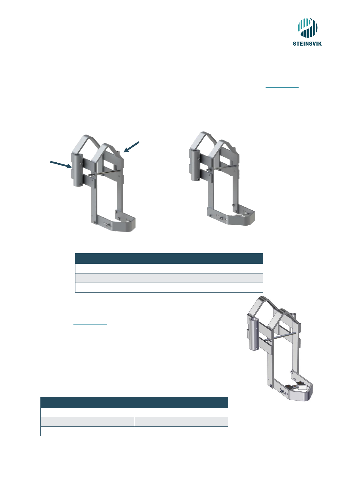
4.5 Orbit-bracket for ring
It is possible to connect the PSU, antenna and Multiwinch to the Orbit-bracket for ring. See chapter 5.2.1
for a description on how to install the bracket for ring.
Orbit-bracket for ring is delivered with a large and a small bottom mounting bracket to accommodate
most of the cages in today’s market.
Figure 5 Bracket with small clamp
Table 5 Specifications Bracket for ring
4.6 Orbit-bracket for ring with clamp
It is possible to connect the PSU, antenna and Multiwinch to the Orbit-bracket
for ring. See chapter 5.2.2 for a description on how to do install the bracket
for ring with clamp.
This version of the Orbit-bracket is delivered with a clamp mounted on the
bottom mounting bracket. This clamp makes it easy to adapt the Orbitbracket to all types/sizes of cages available in today’s market.
This bracket can also be delivered with two different sizes of the bottom
mounting bracket. Figure 7 illustrates the Orbit-bracket w/clamp and small
mounting bracket.
Table 6 Bracket for ring with clamp
Specifications
Material
Aluminium and stainless steel
Weight
7,82 kg
Dimensions (WxHxD)
315 x 502 x 553 mm
Specifications
Material
Aluminium and stainless steel
Weight
7,74 kg
Dimensions (WxHxD)
315 x 502 x 553 mm
Attachment
for mast/PSU
Attachment
for Multiwinch
Figure 6 Bracket with large clamp
Figure 7 Bracket with clamp

15
4.7 Antenna and mast
The antenna sends data from the PSU to the barge. The sticker on the antenna must face the receiving
antenna placed on the barge. For more information regarding mounting and installation, see next
chapter.
For wireless facilities, the antenna is attached to the aluminium pipe on arrival. For fibre facilities the
same aluminium pipe is used for mast to attach the fibre equipment.
Table 7 Specifications Antenna and Mast
Specifications
Antenna
Mast
Material
POM-C (white)
Aluminium
Dimensions (WxHxD)
98 x 325 x 98 mm
1500 x 40 mm
Temperature range
-20°C - +70°C
N/A
Power supply
24 V, 0,5 A (12 W),
max 5,5 W
N/A
Humidity during
operation
5-95%
condensation
N/A
Maximum power
consumption
5 W
N/A
Weight (kg)
1,63
Figure 8 Antenna and mast

16
4.8 Strain relief
The strain relief is delivered with all PSU’s and is used with the fibre cables. It is normally padded before
use.
Table 8 Specifications strain relief
Specifications
Material
Aluminium and stainless steel
Weight
1,5 kg
4.9 Pulley for camera rope3
Table 9 Specifications – Pulley for camera rope
Specifications
Material
Nylon and stainless steel
3
Strips are only for easier transportation – not used in the cage.
Figure 9 Strain relief
Figure 10 Padded strain relief
Figure 11 Pulley for camera rope

17
4.10 Pulleyblock 18 mm
Table 10 Specifications - Pulleyblock
4.11 Camera cable
Steinsvik’s camera cable transfer all signals from the PSU to the camera. The cable can be delivered in
many different lengths, depending on what is required at the locations. It is delivered either as a blue
cable or a black cable where the black cable is enhanced with Kevlar on the outside, while the blue is
not enclosed in Kevlar.
To ensure the best possible utilisation of the system, the recommended length of the cable is diagonally
from the winch to the bottom of the cage on the opposite side.
4.12 Rope Orbit XXXM
Rope Orbit-XXXM can be delivered in many different lengths, all adjusted to the cage in which it is to be
used at. The rope is held tight by the counterweight located outside of the cage, on the oposite end of
where the winch is placed. The counterweight adjust the winchrope according to the movement of the
cage.
Standard lengths for cages are:
- 120M cage: 80M
- 160M cage: 100M
- 200M cage: 120M
When using steel cages, the standard delivery is the size of the cage x2 (ie. 24; cage = 50M rope).
The importance of correct installation is due to the winch experience. The user will have a very slow
experience trying to control the winch if the rope have not been installed correctly. The rope is to be
winded out so that all white and blue lines of the rope are parralell. This might take some time to do
properly, but it is worth spending some time on it in order to save much time at a later stage.
More details about mounting is explained in chapter 5.6.
Specifications
Material
Nylon and stainless steel
Figure 12 Pulleyblock

18
4.13 Surveillance camera
Steinsvik also supplies several surveillance cameras meant for surveillance at the barge. The Orbit-351
and the Orbit-310 are reliable cameras that provides good visibility on the facility and specific parts of
the facility.
4.13.1 Orbit-310
With careful installation of the Orbit-310, you will gain maximum advantage of the camera. The camera
can easily be controlled with a gamepad and has an excellent zoom. In addition to manual control, the
camera can be pre-set to fixed positions via the software. The software allows for control of the camera
with only a keystroke where you can position the camera from the spreader in the outer most edge of
the cage, to the distribution valve at the barge. The Orbit-310 must only be installed at the barge – for
cage installation use Orbit-200/210.
Table 11 Specifications Orbit-310
Specifications
Video signal
Video over IP
Resolution
Full HD 1080p
Sensor type
Colour BSI CMOS
Zoom
30 x optic, 12 x digital
Lens opening
F 1.6
Light sensitivity
0,0015 lux – 50 IRE
Weight
10,5 kg (incl. cable)
IP degree
IP67
Temperature range
-10°C - +50°C
Effect
11-13 VDC, 24 VAC or PoE +30W
Material
Aluminium, PC and POM
Range of motion
360° (horizontal), 90° (vertical)
Focus
Auto
Cable length
30 M
Pan/tilt
Manual and Auto
Figure 13 Orbit-310

19
4.13.2 Orbit-351
The Orbit-351 Stationary Camera is a great tool to help maintain the safety of the crew in areas with
less activity, while at the same time having full monitoring of the spaces on the barge you may want.
This camera can also be used for monitoring the amount of feed in the silo. It is easy to install and
integrate in the software.
Table 12 Specifications - Orbit-351
Specifications
Video signal
Video over IP
Resolution
Full HD 1080p
Sensor type
Colour CMOS
Zoom
3x manual optic
Lens opening
F 1.4
Light sensitivity
0,03 lux – 50IRE
Weight
2 kg
IP degree
IP68
Temperature range
-20°C - +50°C
Effect
12VDC, PoE
Material
Aluminium, PC and POM
Picture angle
113° (horizontal)
Focus
Manual
Pan/tilt
Manual
Figure 14 Orbit-351

20
4.14 Fibre receiver cabinet
The Orbit-502 IP Receiver cabinet is the receiving cabinet for fibre installations on the barge. The cabinet
receive and transmit the signals given from the gamepad to the camera. It can be connected to dome
cameras and has the possibility of connecting to sensors. The sensors are not included in the standard
delivery and must be ordered separately.
Table 13 Specifications Fibre receiver cabinet
Specifications
Material
Aluminium and stainless
steel
Weight
10,10 kg
Dimensions (WxHxD)
500 x 550 x 221 mm
Connections
1 x 230 V power inn
3 x multi connector
1 x 100 Mbit/s Ethernet
2 x 100 Mbit/s Ethernet
2 x Hybrid fibre contact
4.15 Orbit-51X8 for wireless facilities
The Orbit-51X8 is the heart of wireless facilities. It receives and transmit all signals in a digital wireless
facility. The Orbit-51X8 has the possibility of connecting to dome cameras and it is possible to upgrade
the cabinet to accommodate sensor connections as well.
Table 14 Specifications Orbit-51X8
Specifications
Material
Aluminium and stainless steel
Weight
10,90 kg
Dimensions
(WxHxD)
555 x 351,3 x 408 mm
Connections
1 x 230 V power inn
2 x multi connector
7 x PoE 100 Mbit/s Ethernet
7 x 100 Mbit/s Ethernet
Figure 15 Fibre Receiver Cabinet
Figure 16 Orbit-51X8

21
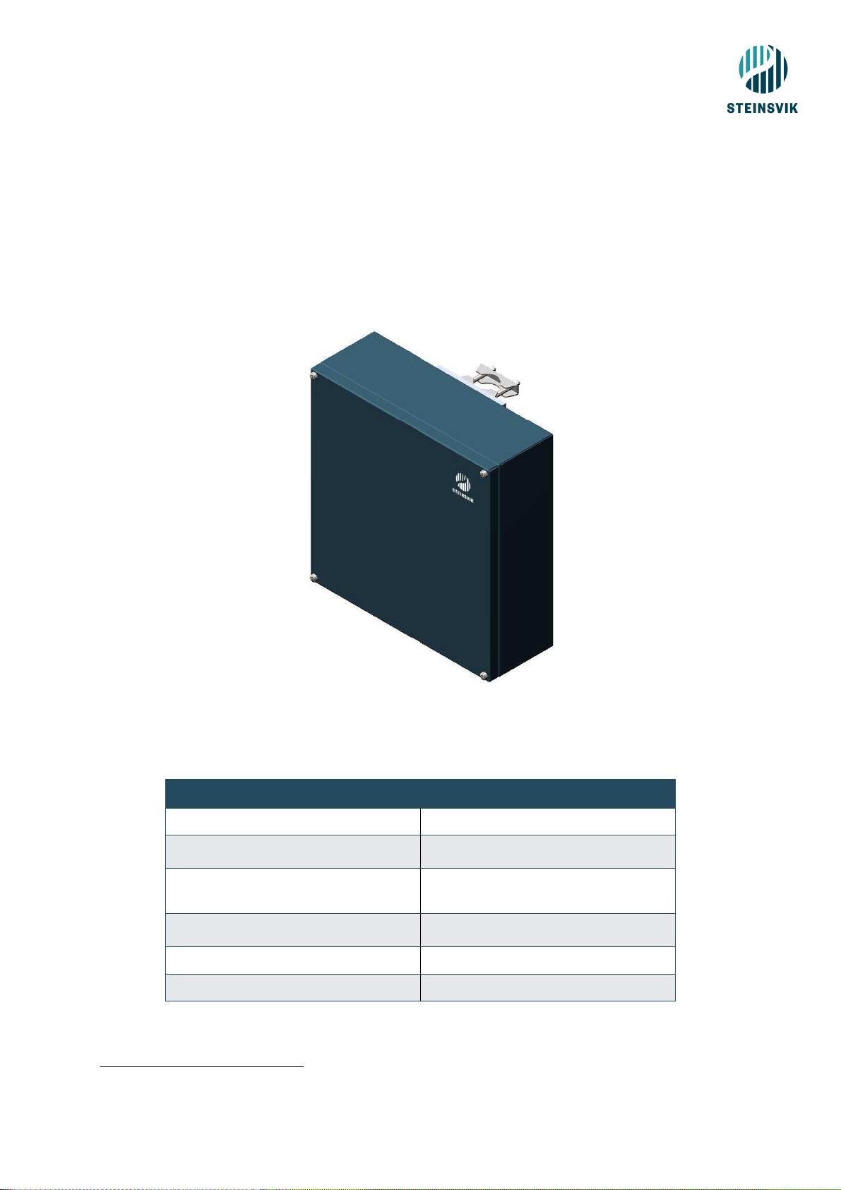
4.16 Protection cabinet for PSU
Table 15 Specifications Protection cabinet
Specifications
Material
Stainless steel4
Weight
18,42 kg
Dimensions (WxHxD)
466,20 x 649 x 273 mm
4
Steinsvik AS also delivers protection cabinets for plastic PSU’s.
Figure 17 Protection cabinet for SS PSU

22
5 PREPARATION AND INSTALLATION
Perform a visual inspection before and after installation to eliminate any potential
risk for personnel and fish.
When reinstalling the equipment, (new generation) it is important to ensure that the installation
and equipment are in accordance with specifications provided by Steinsvik AS. The use will
not cause any contamination of fish.
5.1 Antenna
− Connect the antenna to the mast. The cable from the antenna is routed through the
mast.
− Attach the mast to the Orbit bracket for ring, as shown in chapter 5.3.
− The cable from the antenna is then connected to the “Multi contact” on the PSU.
Note: The antenna is marked with a TX-number. Connect the antenna to the PSU with the
same number. Example: connect the antenna marked “TX: 01” to the PSU marked “PSU:
01”. The sticker on the antenna must be faced towards the barge.
Tip: Install the antenna on the barge before you install the antenna on the cage to ensure that
the antenna is pointing in the right direction.
5.2 Orbit Bracket for ring
Find a suitable place to place the Orbit-bracket for ring:
• Place it so that the winch rope moves either with or against the current.
• Position it so that it is not placed on a post where the chains to the bottom ring emerge.
• Make sure it does not conflict with ropes for the dead fish net/lift-up.
• Position it so that it is not in the way for any live-hauling boats and other vessels that may
damage the equipment.
5.2.1 Mounting Orbit-Bracket for ring
Place the bracket over the top ring of the cage.

23
Insert the supplied bolt, washer and locking pin so that the bracket cannot fall off.
The mounting bracket goes around the support rail (picture). Fasten this with a M10x20 bolts in the
top hole (on both sides). In the bottom hole (on both sides) the M10x30 bolts and M10 nuts are
fastened.
NOTE: The bolts are fastened from the inside so that they point away from the net/cage net.
Fasten the locking bolt (196mm) in the mounting bracket. This prevents the bracket from moving
sideways on the cage ring.
Drill a new hole if the support ring is to wide.

24
5.2.2 Mounting Orbit-Bracket for ring with V-clamp
Place the bracket over the top ring of the cage.
Insert the supplied bolt, washer and locking pin so that the bracket cannot fall off.
The mounting bracket goes around the support rail (picture). Fasten this with a M10x20 bolts in the
top hole (on both sides). In the bottom hole (on both sides) the M10x30 bolts and M10 nuts are
fastened.
NOTE: The bolts are fastened from the inside so that they point away from the net/cage net.

25
Bring the clamp up to the support rail. Fasten it with the supplied locking bolt, washer and locking pin
through the bracket and clamp (see picture). Depending on the size of the support rail, the locking
bolt is placed in the hole which fits the best on the bracket
Adjust the size of the clamp so that it holds the Orbit-bracket in place by turning the nut on the right
side on the clamp (the white nut in the illustration above). Fasten the clamp by tighten the locking nut
(bronze coloured nut in the illustration to the right above).

26
5.3 Mast/Alu pipe
5.3.1 Wireless installations
Fasten the aluminium pipe into the 40 mm pipe on
the Orbit-bracket for ring.
The mast is supposed to rest on the bolt at the
bottom of the 40 mm pipe. Secure it with a set
screw (DIN 912 M8x16).
5.3.2 Fibre installations
Fasten the aluminium pipe into the 40 mm pipe
on the bracket. There must be at least 300 mm of
pipe under the bracket.
Secure the pipe with a set screw (DIN 912
M8x16) on the bracket.
Place the strain relief at the bottom of the pipe.
Fasten the strain relief with M10x80 (DIN 912)
bolt and M10 nut (through the hole on the strain
relief and into the hole at the bottom of the mast).

27
5.4 PSU/Protection cabinet
Fasten the PSU to the mast, as high up as possible. Attach the four nuts to the backside of the PSU.
If an extra protection cabinet is used, place the PSU into the cabinet before mounting it on the mast.
Remember to secure the protection cabinet with an extra bracket so that there is a total of 6 nuts fastened
on the backside.

28
5.5 Winch and winch rope
Place the washer for the winch bolt on top of the attachement point for the winch on the Orbit bracket for
ring.
Slide the winch over the washer.
Attach the bolt. The winch should be able to rotate
to both sides.
Attach the locking pin at the bottom of the bolt to
prevent the winch from falling off the bracket.
Attach the winch cable. One end is connected under
the winch, while the other is connected to the
“Winch” contact in the PSU. Make sure that the net
is not in a position for the winch cable to hook onto
and break. The winch cable should preferably be
secured around the top row before it is fastened at
both ends.

29
Apply Molykote 44 or Molykote 111 on the contact surface of the winch cable to prevent
moisture from entering.
Connect everything else before connecting to 230 V.
5.6 Rope and strain relief
The strain relief consists of a 25 kg counterweight, a rope and various blocks. The purpose is to keep
the winch rope tight even if the cage is deformed due to wind, currents or other factors.
Wind up the winch rope before it is pulled around the cage.
All white and blue lines in the rope must be parallel throughout the rope to avoid
knots/twisting of the rope.
• Fasten one end of the winch rope to the handrail of the cage and wind the rope out, either lying
in the sea or between the collar tubes.
• Pull the other end of the rope through the block hanging from the strain relief. Then tie it to the
handrail.
• Walk around the cage with the strain relief. The rope is supposed to place itself nicely out in the
cage.
Place the winch rope between the ropes for the spreader, birds net etc., and above the
rope for the dead fish handling system, lights, etc.
− Walk as far as possible with the strain relief so that the winch rope is placed where the feed
lands in the cage, preferably centred in the cage so that it is possible to lower the camera all
the way down to the dead fish handling system.
− Attach the strain relief to the handrail via the pulley.
− Attach the counterweight to the end of the strain relief and lower it into the sea. Steinsvik AS
recommend fastening a safety rope to the counterweight.
− Wind the winch rope onto the winch.
− Cut the rope to the appropriate length – the length is dependent on the size of the cage
− Tie the small block for winch rope to the rope.
− Thread the camera rope through the steering rod on the winch and through the block (which
you mounted on the winch).
− See chapter 5.7 for installation of the underwater camera and cable.

30
5.7 Underwater camera
− Connect everything else before connecting to 230 V.
− Disconnect power supply before disassembly.
− Inspect for any damage on the metal hoop on the camera before submerging the
camera
− When the camera contact is disconnected from the rest: remove all sand and growth
with isopropyl alcohol and apply Molykote before reassembly.
− Tie the camera rope from the Multiwinch to the hoop on the underwater camera.
− Apply a thin layer Molykote 44 (approx. 1/10 of the depth of the contact, approx. 1 mm).
− Attach the camera cable to the camera.
− Ensure that the camera is hanging correctly; the rope should keep the plug in the right
position.
Figure 18 Camera contact, metal hoop on
camera and camera rope

31
- The camera rope is supposed to tensions relieve the camera cable so that both the camera and
the camera cable is lifted by the rope (from the Multiwinch).
− Lower the camera into the sea and wind the camera cable out in the cage.
− Cut off some meters of the white winch rope and tie a strain relief to the camera cable. Attach
this to the handrail. This is to avoid unnecessary tension/strain to the contact/connection in the
PSU.
− Connect the camera cable to the «Camera» connection in the PSU.
Figure 19 Camera Rope

32
5.8 Surface camera
Attach the Orbit-200B/210 to the top of the mast at the cage. Place the camera in the direction you want
to look.
On PSU’s supporting surface cameras: connect the camera cable to the «Multi contact» marked with
a green circle on the PSU.
5.9 Surveillance camera
− Attach the Orbit-310 to the mast at the barge (after attaching the mast to the bracket).
− Use the 40 mm U-bolt, washers and nuts supplied.
− Attention: This camera is not supposed to be mounted at the cage edge!
− Connect the camera cable to the «Multi contact» on the receiver cabinet located at the barge.
The camera cable is equipped with a 7-pin contact and a 15-pin contact. The 7-pin contact
connects to the camera, while the 15-pin contact connects to the receiver cabinet.
Figure 20 Surface camera
Figure 21 Surveillance camera

33
6 OPERATING INSTRUCTIONS
6.1 Multiwinch/underwater camera
The camera system is primarily controlled via the NeoVision or Vision software on a computer or a
control desk located on the barge or land base.
It is also possible to operate the winch from the cage edge, this makes accessing the camera for
maintenance/inspection purposes easier. The winch has three buttons, these are marked with “up”,
“down” and “sideways”:
1. Press “Up” to: Move the camera up
2. Press “Down” to: Move the camera down
3. Press “Sideways” to: Move the camera from the winch
4. Press “Sideways” to: Move the camera towards the winch
Alternately, an older winch may only have two buttons, one to move the winch up/down, one to move it
sideways, and both buttons must be used to move the camera to/from the winch.
Consult the NeoVision/Vision user manual for a complete description of navigation and
configurations.
6.2 Surveillance camera
The surveillance camera is controlled via the NeoVision or Vision software on the PC. It can be
controlled via the gamepad, arrows on the PC’s keyboard or by clicking on the different arrows in the
camera software.
Some of the functions on the gamepad are shown in the figures below.
Consult the NeoVision/Vision user manual for a complete description of navigation and
configurations.

34
Figure 22 Gamepad
Figure 23 Gamepad backside

35
7 MAINTENANCE
7.1 Routine inspection and periodic maintenance
Table 16 Routine inspection and periodic maintenance
Component
Description
Interval
Daily
Weekly Monthly
5
Entire system (incl. cables
and antennas)
Check for any icing during the winter
months. Remove ice if found on any
equipment.
Screws on the PSU/Winch
Check that all screws for lids are fastened
and in place
Multiwinch
Wipe around cables to prevent mussels from
attaching themselves between the plate and
rope cables.
Underwater camera
Run the camera to both edges to prevent
growth.
Underwater camera
After use: park the camera centered in the
cage at a depth of 10 m with the lens facing
down to prevent growth on the lens.
Underwater camera
Wipe the camera lens
Surface/surveillance/dome
camera
Visual inspection of lenses and
cables/contacts – clean/replace if necessary
Antennas
Visual inspection of cables, contacts and
fastening equipment for any bends/damage.
Visual inspection of dome.
Rope
Scrape off all growth from the knots in the
rings
Rope
Visual inspection
Orbit bracket for ring
Check fastening point to cage; check that
bolts and suspension are properly fastened.
Winch rope
Visual inspection for damage
Winch rope
Visual inspection for growth
Sensor station
Wipe the membrane on the sensor station2F6
Strain relief
Visual inspection
Counterweight
Clean to remove growth
Suspension rings
Visual inspection
Cables
Ensure that the cables do not have any
damages/kinks
5
When possible when you are at the cage
6
Use a soft cloth/Q-tip to avoid damaging the membrane

36
PC at barge
Check that it has sufficient air flow and no
dust/dirt in the fan
Gamepad
Keep clean with a damp cloth to prevent the
buttons from sticking. N.B: Not waterproof!
7.2 Larger reparations and modifications
All service must take place at Steinsvik AS or with authorized partners.
Steinsvik AS recommend sending the underwater camera in for service after every generation, while
the winch and PSU can be sent in for service every other generation.
Calibration and/or change of oxygen film on the underwater camera must be sent in to Steinsvik AS
when needed (damage). Estimated lifetime without damage is 5 years.
7.3 Troubleshooting and correction of errors
Table 17 Troubleshooting
Problem
Possible cause
Solution
Winch will not work
Growth on the rope
Remove growth
Winch will not work
Winch rope is jammed
Loosen knots
Winch will not work
Broken winch cable
Check that the cable is whole
and without visible
marks/damages. If the cable is
broken, check for corrections on
contacts on cable and in PSU.
Winch will not work
The camera rope is on the
outside of the circlip
Thread the camera rope to the
inside of the circlip.
Winch will not work
Broken fuse
Check the fuse on the inside of
the PSU and change if this is
broken.
Note: authorized personnel only
Winch jerks or stops
before reaching the
bottom
Misplaced bottom stop switch
Raise the hoop stopper7 up and
down to the stop screw. Approx.
5 mm from the bottom position
there should be a “click” from
the switch inside the winch. If
the hoop must be raised 1 cm or
more, the bottom stop switch is
misplaced.
Winch jerks or stops
before reaching the
bottom
Error on the motor protection
on the circuit board.
The motor protection switches
on when the motor is
overloaded, and the winch will
disconnect the motor when the
camera is lifted approx. 1 m
above the water surface. This to
7
Hoop that holds the winch rope up

37
prevent the engine from tearing
the ropes or burning out.
Steinsvik recommend a service
on the winch if it fails to lift the
camera in the water.
Picture come and go
Broken camera cable
Replace camera cable or try with
a cable from a different cage.
«No video» on pc-screen
Camera is not connected to
the PSU
Ensure the camera is properly
connected
«No video» on pc-screen
Defective camera fuse
Use «camera tools» in the
software to check status on the
fuse. If the fuse is broken, verify
what caused this before
changing the fuse.
7.4 Link to troubleshooting for camera system
https://help.steinsvik.no
7.5 Storing, preservation and maintenance
Disconnect power supply before disassembly
Steinsvik AS recommend storing the equipment indoors. This includes the Orbit-bracket
for ring and ropes.
1. Clean the ropes for any growth and rinse with clean water. Check for any damages resulting
from wear and tear and order new ropes if necessary.
2. Rinse aluminium parts with clean water. To avoid oxidation, cover all contact surfaces/screw
threads with grease.
3. Rinse, clean and wipe dry all cables to remove any salt residues. Check for wear and tear,
change if necessary. Coil the cables together for storage.
4. Clean the camera to remove all growth. Steinsvik AS recommend sending the camera for
service after every generation (change gaskets, calibration of sensors).
5. Clean the winch and PSU for salt and check all contacts; Evaluate whether to submit for service
to prepare it for a new generation. Store indoors to prevent moisture from entering contacts and
lid when not in the intended position (contacts down).
6. Fibre cable: If the plug of the fibre cable has come into contact with saltwater during
disconnection, rinse it immediately in clean water. Allow to dry completely before reinstalling the
lid. When coiling the cable make sure that the cable is not heavily bent; min. bending radius is
50 cm to avoid damage to fibres.

38
8 SPARE PARTS
8.1 Underwater camera
Orbit-3100: 417854
Orbit-3300: 406632
Orbit-3500: 410481/420590
Orbit-3400: 430463
Orbit-3600: 421021
8.2 Obrit-200 (411340) and Orbit-210 (430755)
Pos. nr.
Description
Product
number
Amount
1
ISO 4762 M6 x 40 A4
2
2
Washer DIN 125 - B 6.4 300HV
2
3
Spring washer DIN 128 A6
2
4
Clamp 2
406467
1
Optional
Winter sunshade
406615
1
Pos. nr.
Description
Product
number
Amount
Silicone oil
Membrane
406293
1

39
8.3 Multiwinch (100069)
Item No.
Product
Product No.
Qty.
3
Washer for shaft
1
8
Bolt for winch
405571
1
19
Split pin
401670
1
10
Hanger
401311
1
Rope 3 mm nylon
403620
100m
12
Pan head cross recess screw M6x16
4
13
Pan head cross recess screw M4x16
1
15
Plain washer M6
4
16
Plain washer DIN 9021-4.3
1
20
Wing nut M4
401611
1
6
Locking plate
405819
1
5
Winch cover
432039
1

40
8.4 Orbit-Bracket for ring (405461)
Pos. nr.
Description
Product
number
Amount
1
Mounting Bracket (small)
Mounting bracket (large)
417314
420304
1
2
12mm locking bolt 196mm
405721
1
3
12mm locking bolt 237mm
418684
2

41
8.5 Orbit-bracket for ring with clamp (V-Clamp) (442778)
Pos. nr.
Beskrivelse
Varenummer
Antall
1
12mm locking bolt 196mm
405721
1
2
12mm locking bolt 237mm
405830
1
3
V-Clamp Assy
420297
1
4
Mounting Bracket (small)
Mounting bracket (large)
417314
420304
1
Bolt set
442197
1

42
8.6 Antenna (411859)
Pos. nr.
Description
Product
number
Amount
1
Top cover
405259
1
2
O-ring 77x4,0
405263
1
3
Antenna
411156
1
Cable (complete) 2,5m
420441
1
8.7 Strain Relief (420438)
Pos. nr.
Description
Product
number
Amount
1
DIN EN ISO 10511 - M10
5
2
DIN 912 M10 x 80
5
3
DIN 912 M8 x 16
1

43
8.8 Orbit-310 (410478)
Pos. nr.
Description
Product
number
Amount
1
Countersunk flat head
cross recess screw ISO
7046 M8x30
4
2
Baseplate
410982
1
3
Washer DIN 129-9
4
4
Prevailing torque nut DIN
EN ISO 7042 M8
4
Cable 30m
430338
1
44
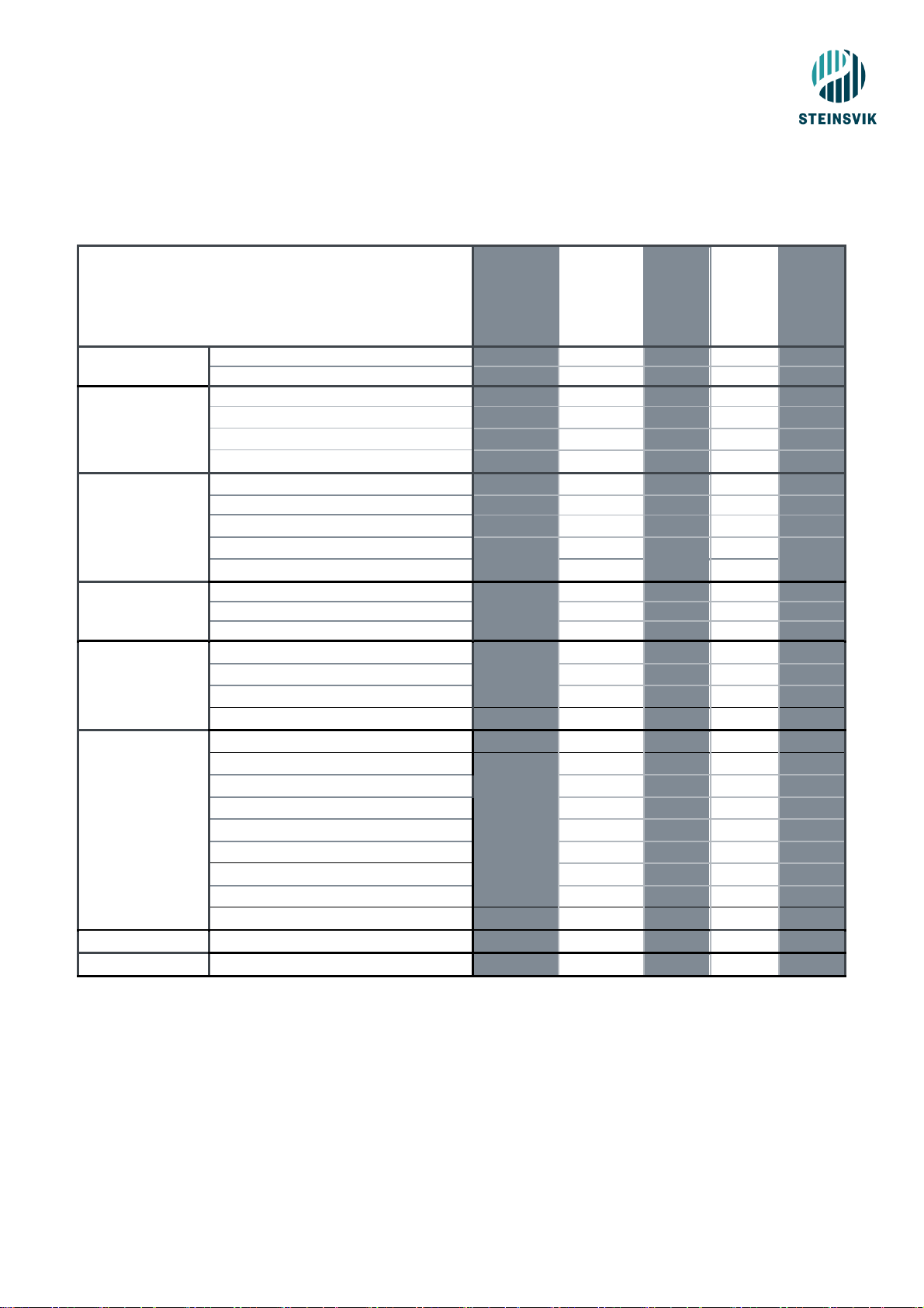
9 ORBIT-PSU STAINLESS STEEL
Orbit 542
-SS
(440221) Orbit-548SS
(100043)
Orbit-571SS
(100068)
(UK only) Orbit-578SS
(100066)
Orbit-579SS
(100067)
Video server
Siqura EVE ONE
4 1 2
Orbit-2560 1
Network switch
Korenix JetNet 4508f-m V2
Korenix JetNet 2005f
✓ ✓ ✓
Korenix JetNet 6059G
✓
Orbit-2520
✓
Contacts
Fiber & power in and out
✓
✓
1 fiber & power in, 5 fiber & power out
24 VDC PoE.
✓
Power in and out
✓
✓
Power in
✓
Connectors
Camera connector
4 4 1 1 1
Winch connector
4 4 1 1 1
Multiconnector
2 2 2 2 2
Supported by
Software
NeoVision6.0 and newer
✓ ✓ ✓
✓
NeoVision6.1 and newer
✓ ✓ ✓
✓
NeoVision6.2 and newer
✓ ✓ ✓
✓
Vision
✓
✓
✓ ✓ ✓
Supported by
Camera
Orbit-3000
✓ ✓ ✓
✓
Orbit-3100
✓ ✓ ✓ ✓
Orbit-3300
✓ ✓ ✓
✓
Orbit-3400
✓
Orbit-3500
✓ ✓ ✓
✓
Orbit-3600
✓
Orbit-200 ✓
✓
Orbit-200B ✓
✓
Orbit-210
✓
✓
✓
Material (cabinet)
Stainless steel
✓ ✓ ✓ ✓ ✓
Logging Module
Can be fitted
✓
✓ ✓ ✓
✓

45
Orbit-518SS
(100065)
Orbit-519SS
(418597)
Orbit-520SS (430992) Orbit-521SS
(430453)
Orbit-522SS (440222) Orbit-528SS
(100058)
Video server
Siqura EVE ONE
1 2 1 2 Orbit-2560
Network switch
Korenix JetNet 4508f-m V2
✓ ✓ ✓ ✓ ✓
Korenix JetNet 2005f
Orbit-2520
✓
Contacts
Fiber & power in and out
✓ ✓ ✓ ✓ ✓
✓
1 fiber & power in, 5 fiber & power out
24 VDC PoE. Power in network
Power in and out
Connectors
Camera connector
1 1 1 1 2 2 Winch connector
1 1 1 1 2 2 Multiconnector
2 2 2 2 2
2
Supported by
Software
NeoVision6.0 and newer
✓
✓
✓
NeoVision6.1 and newer
✓
✓
✓
NeoVision6.2 and newer
✓
✓
✓
Vision
✓
✓ ✓ ✓
✓
✓
Supported by
Camera
Orbit-3000
✓
✓
✓
Orbit-3100
✓
✓
Orbit-3300
✓
✓
✓
Orbit-3400
✓ ✓ ✓
Orbit-3500
✓
✓
✓
Orbit-3600
✓ ✓ ✓
Orbit-200
✓ ✓
Orbit-200B
✓ ✓
Orbit-210
✓ ✓ ✓
✓
Material (cabinet)
Stainless steel
✓ ✓ ✓ ✓ ✓
✓
Logging Module
Can be fitted
✓ ✓ ✓
✓ ✓ ✓

46
 Loading...