

Page 1

LAWN SWEEPER
Model LS340
Starting Serial No. 1001
Owner/Operator's Manual
& Illustrated Parts List
CAUTION
Avoid injuries. Read and understand Operator’s manual
before operating tractor or equipment.
It contains instructions for safe operation.
Form # 09-164
Page 2

CAUTION
• READ AND UNDERSTAND OPERATORS MANUAL
BEFORE OPERATING OR SERVICING.
• OBEY ALL SAFETY INSTRUCTIONS. FAILURE TO DO SO
MAY RESULT IN INJURY TO YOU OR OTHERS.
• BE SURE MACHINE IS IN SAFE OPERATING CONDITION
BEFORE USE.
• INSPECT MACHINE DAILY. REPLACE ALL WORN OR
DAMAGED PARTS.
• KEEP ALL GUARDS AND SHIELDS IN PLACE.
• CHECK OPERATION OF ALL SAFETY INTERLOCK
SWITCHES DAILY.
• DO NOT OVERRIDE INTERLOCK SYSTEM, IT IS FOR YOUR
PROTECTION.
• DO NOT ALLOW MINORS OR THE INEXPERIENCED TO
OPERATE MACHINE.
• KEEP PEOPLE AND PETS A SAFE DISTANCE AWAY FROM
MACHINE USING POWER DRIVEN ATTACHMENTS.
INJURY COULD RESULT FROM FLYING DEBRIS.
Date of Purchase: Month ________________Day____________________Year _______________
Dealer Name _________________________Phone__________________
Serial Number ________________________
Model Number ________________________
ALWAYS GIVE MODEL AND SERIAL NUMBER WHEN ORDERING SERVICE PARTS
STEINER TURF EQUIPMENT, INC.
289 N. Kurzen Rd., P.O. Box 504
Dalton, Ohio 44618
Telephone: (330) 828-0200
FAX: (330) 828-1008
Page 3

TABLE OF CONTENTS
INTRODUCTION SECTION 1 page
Description ..........................................2
Specifications .........................................3
SAFETY SECTION 2
General Safety.........................................4
Operator Safety ........................................4
OPERATION SECTION 4
Operating Instructions ....................................5
SERVICE SECTION 5
Service Schedule .......................................6
PARTS SECTION 6
Parts List and Illustrations Index ...............................7
Warranty
12
Form #09-164 reprint 2/96
1
Page 4
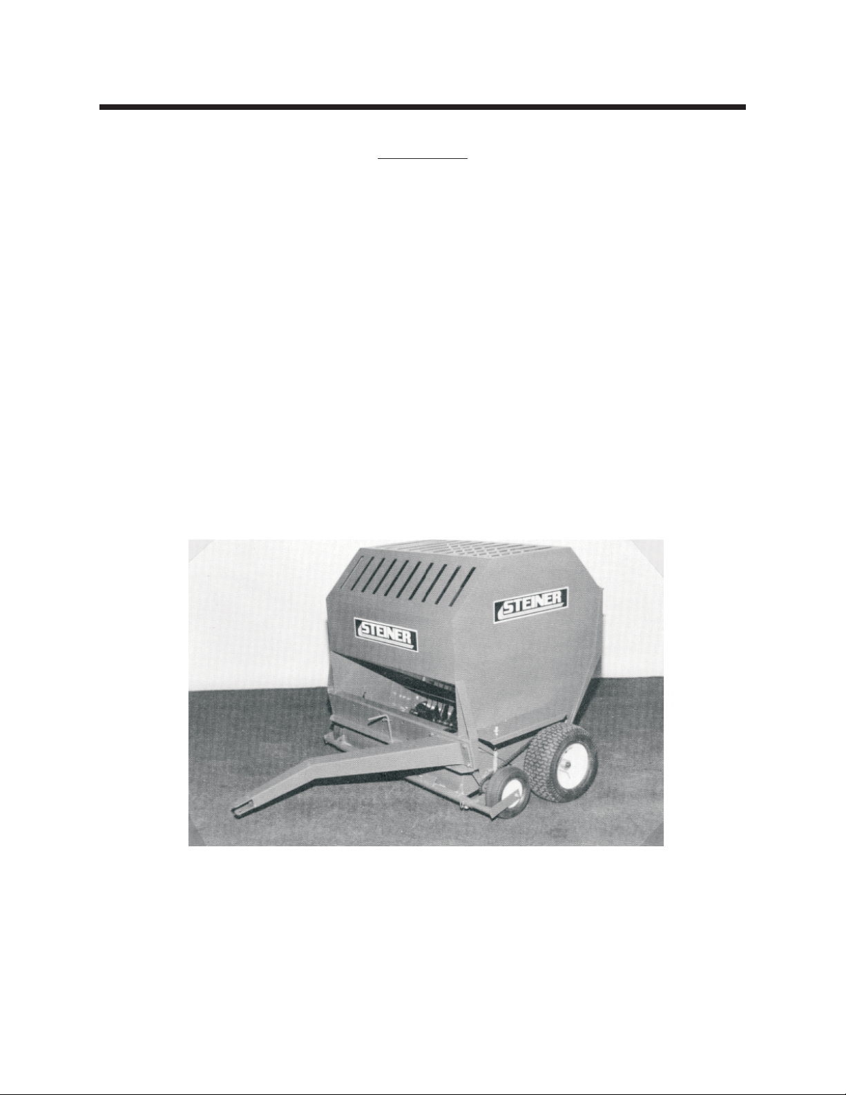
INTRODUCTION section 1.1
Description
The Steiner Lawn Sweeper is designed to give a “clean sweep” in your lawn sweeping operations.
The unit is ground-driven so it can be pulled by any lawn and garden tractor. It can be used to trail behind
with offset hitch while mowing, or regular hitch to clean-up after you've finished mowing. The packing action
allows you to put much more material into the unit before it is necessary to unload.
There is a transport position for the sweeper and clutch levers on each wheel to disengage the wheel
clutches.
2
Page 5
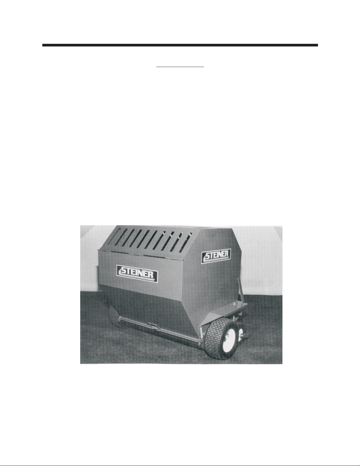
INTRODUCTION section 1.2
Specifications
Overall width ______________62"
Overall height ______________52"
Overall length to hitch___________66"
Width of pick up _____________40"
Brush _________________3paddle, staggered
Depth wheels ______________Semi-pneumatic
Hitch __________________Right, left or center pull adjustment
Carrying capacity ____________24cu.ft.
Weight _________________530lb.
3
Page 6

SAFETY section 2.1
BE ALERT!
ATTENTION: This symbol identifies potential health and safety hazards. It marks safety
precautions.
ATTENTION: Your safety is involved.
1. Read and understand the owner's manual,
before attempting to operate this machine.
2. Operate all controls from the operator's
seat. NO RIDERS.
3. Keep all shields in place and safety switches
adjusted properly.
1. Remove large objects or debris from the path
of the lawn sweeper..
2. Before leaving the tractor seat to clear
blockage, service or make adjustments:
1. Set PARKING brake.
2. Stop Engine.
GENERAL SAFETY
4. Do not leave equipment unattended. STOP
the engine and remove the key.
5. Do not allow minors or the inexperienced to
operate this machine.
6. Keep people and pets a safe distance away
from machine using power driven attachments. Injury
could result from flying debris.
OPERATING SAFETY
3. Disengage clutches and raise broom to
transport position before transporting at high speed.
4
Page 7

OPERATION section 4.1
Operating Instructions
1. Determine hitch position for offset or straight pull position.
›
2. Transport to clean-up site with the clutches disengaged and sweeper in transport position.
›
3. Lower the sweeper housing and adjust sweeper height on right side of sweeper housing by
›
choosing the pin location to regulate gauge wheel height. NOTE: Operation is best when the
sweeper is approximately 1/2" below the tips of the grass, but does not “scrub” the lawn.
4. Adjust the float springs allowing the sweeper to “float” over rough areas or high spots in the lawn.
›
5. Engage clutches on both wheels by rotating the lever approximately 180 deg.
›
6. When sweeping leaves - the best results are obtained by sweeping several times during the leaf
›
fall rather than waiting until there is a large accumulation. A large accumulation will require several
passes to make a clean sweep. MAXIMUM SPEED IS 10 M.P.H.
7. Open rear door to unload.
›
› 8. To transport - Always disengage wheel clutches and raise sweeper housing. DO NOT TRAVEL AT
HIGH SPEEDS WITH CLUTCHES ENGAGED! MAXIMUM SPEED IS 10 M.P.H. NOTE: to disengage
both wheels rotate each lever approximately 180 deg. You can feel a high spot when it is
disengaged.
CAUTION
Do not travel at high speeds with clutches
engaged. MAXIMUM SPEED IS 10 M.P.H.
Disengage clutches for transport.
MAXIMUM SPEED IS 10 M.P.H.
09-164 5 7/89
Page 8

SERVICE Section 5.1
Maintenance
Daily
Visually check chain drive - it should not run “dry”.
Lube with chain lube or 30W oil
Weekly or 50 Hours
Grease all bearings and wheels.
Check tire pressure (12 lbs.)
rev 6/00 6 09-164
Page 9

PARTS Section 6.1
Parts Index
GROUP FIGURE PAGE
Main Parts.................Fig. 1 .......................8
Brush Parts ................Fig. 2 .......................10
7
Page 10
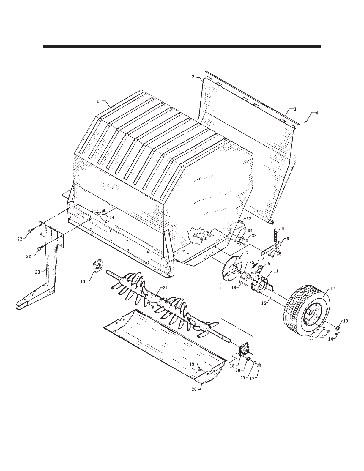
PARTS section 6.2
Main Parts
Figure 1
rev 6/00 8 09-164
Page 11

PARTS section 6.3
Parts List for Figure 1
Ref Part no. Description Quantity
1 62-602 Main Frame 1
2 60-187 Door 1
3 42-205 Hinge Rod 1
4 02-CP0406 Cotter Pin, 1/8 x 3/4 2
5 41-010 Spring, 5" 2
6 40-114 Latch, Right 1
40-115 Latch, Left 1
7 83-407016 Sprocket 1
8 41-013 Spring 2
9 86-020 Clutch Pawl, Right 1
86-021 Clutch Pawl, Left 1
10 85-K0410 Key, 1/4 x 1-1/4 3
11 86-043 Clutch 2
12 50-030 Wheel & Tire Assembly 2
53-089 Tire, 16 x 7.50 x 8, Turfsaver 1
50-101 Rim 1
55-IB-1 Bearing 1
* 29-053 Grease Fitting, 1/4-28 long 2
13 95-16 Flat Washer, 1" SAE 7
14 02-CP0612 Cotter Pin 2
15 92-05 Nut, 5/16 12
16 90-0528 Bolt, 5/16 x 3-1/2 6
17 92-06 Nut, 3/8 8
18 55-FB22016 Bearing 2
19 90-0610 Bolt, 3/8 x 1-1/4 8
20 60-188 Bottom Pan 1
21 80-124 Packer Rotor 1
22 90-0810 Bolt, 1/2 x 1-1/4 4
23 62-357 Hitch 1
24 92-08 Nut, 1/2 4
25 86-044 Hub, Clutch Drive 2
* 00-001 Decal, Steiner Large 4
27 96-08 Lock Washer, 1/2 4
28 94-06 Flat Washer, 3/8 USS 12
29 96-06 Lock Washer, 3/8 8
30 96-05 Lock Washer, 5/16 6
31 85-SC06 Set Collar, 3/8 ( After Serial #1097) 4
32 99-K02 Flange Bolt, 5/16 x 1 (After Serial #1097) 4
33 99-E12 Flange Nut, 5/16 (After Serial #1097) 4
34 64-535 Stop, Adjustable Latch (After Serial #1097) 2
35 99-A06 Locknut, Stover 3/8 2
36 90-0608 Bolt, 3/8 x 1 2
* Not Illustrated
09-164 9 rev 6/01
Page 12
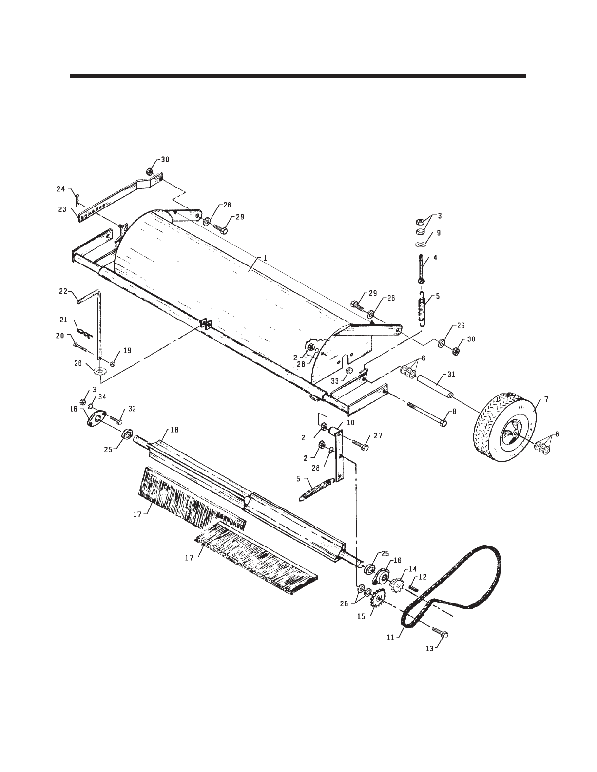
PARTS section 6.4
Brush Parts
Figure 2
rev 6/00 10 09-164
Page 13

PARTS section 6.5
Parts List for Figure 2
Ref Part no. Description Quantity
1 62-385 Housing, Brush 1
2 92-08 Nut, 1/2 3
3 92-06 Nut, 3/8 8
4 42-209 Adjuster, Spring Tension 2
5 41-010 Spring, 5" 3
6 95-10 Flat Washer, 5/8 SAE 12
7 53-104 Wheel, 10.25 x 3.25 Caster (Serial No. 1001 - 1559) 2
55-G527 Ball Bearing for 53-104 2
55-107 Bearing, 5/8 ID x 1-3/8 OD (Optional, Heavy Duty) 2
53-186 Wheel, 10.25 x 3.25 Caster (Serial No. 1560 - ) 2
55-112 Bearing, Roller 5/8 ID X 1-3/8 1
53-187 Retainer, Flanged For 53-186 2
8 90-0640 Bolt, 3/8 x 5 2
9 94-06 Flat Washer, 3/8 USS 2
10 40-227 Idler Arm 1
11 56-RC40-59 Chain, Drive #40, 59" long 1
81-056 Connector Link, #40 Chain 1
81-076 Half Link, #40 Chain 1
12 85-K0410 Key, 1/4 X 1-1/4 1
13 90-0816 Bolt, 1/2 x 2 1
14 83-H401216 Sprocket 1
15 83-4017E08 Idler Sprocket 1
16 55-FB23016 Flange Bearing, 2 Bolt, 1" 2
17 79-017 Brush, Strip 6
18 80-125 Rotor, Brush 1
19 99-A04 Locknut, Stover 1/4 1
20 90-0412 Bolt, 1/4 X 1-1/2 1
21 02-PP0420 Presto Pin, 1/8 x 2-9/16 1
22 42-207 Transport Handle 1
23 42-206 Height Adjuster 1
24 02-PP0318 Presto Pin, 3/32 x 2-5/16 1
25 85-SC16 Set Collar, 1" 2
26 95-08 Flat Washer, 1/2 SAE 6
27 90-0820 Bolt, 1/2 X 2-1/2 1
28 96-08 Lock Washer, 1/2 2
29 90-0810 Bolt, 1/2 x 1-1/4 2
30 99-A08 Locknut, Stover 1/2 2
31 50-062 Shaft, Wheel 2
32 90-06010 Bolt, 3/8 X 1-1/4 4
33 99-E13 Flange Nut, 3/8 2
34 96-06 Lock Washer, 3/8 4
09-164 11 rev 2/01
Page 14

 Loading...