

Page 1

OWNER/OPERATOR’S MANUAL
& ILLUSTRA TED PARTS LIST
MODELS:
75-70855 MOWER DECK-48” MD448
75-70860 MOWER DECK-60" MD460
75-70865 MOWER DECK-72" MD472
WARNING: If incorrectly used this machine can cause severe injury . Those who use
and maintain this machine should be trained in its proper use, warned of its dangers
and should read the entire manual before attempting to set up, operate, adjust or
service the machine.
09-254B REV D
Page 2
CALIFORNIA
Proposition 65 Warning
WARNING
Diesel engine exhaust and some of
its constituents are known to the State
of California to cause cancer, birth
defects and other reproductive harm.
Californie Proposition 65
Avertissement
Les échappements des moteurs diesel
et certains de leurs composés sont
reconnus par l’Etat de Californie pour
être cancérigènes, provoquer des
défauts congénitaux et d’autres dangers
en matière de reproduction.
California Advertencia
de la Proposicion 65
The engine exhaust from this product
contains chemicals known to the State
of California to cause cancer, birth
defects or other reproductive harm.
AVERTISSEMENT
L’émission du moteur de ce matériel
contient des produits chimiques que
l’Etat de Californie considère être
cancérigènes, provoquer des défauts
congénitaux et d’autres dangers en
matière de reproduction.
ADVERTENCIA
El estado de California hace saber que
los gases de escape de los motores
diesel y algunos de sus componentes
producen cáncer, defectos de
nacimiento y otros daños en el
proceso de reproducción humana.
© 2003, TEXTRON INC
El estado de California hace saber
que los gases de escape de este
producto contienen productos
quÍmicos que producen cáncer,
defectos de nacimiento y otros daños
en el proceso de reproducción
humana.
Page 3

ROTARY
MOWER
IMPORTANT MESSAGE
Thank you for purchasing this Jacobsen product. You have purchased a world class product, one of the best
designed and built anywhere.
This product comes with an Owner/Operator's Manual. The useful life and good service you receive from this
product depends to a large extent on how well you read and understand this manual. Treat this product properly
and adjust it as instructed, and it will give you many years of reliable service.
See a Jacobsen dealer for any service or parts needed. Jacobsen service ensures that you continue to receive
the best results possible from Jacobsen products. You can trust Jacobsen replacement parts because they are
manufactured with the same high precision and quality as the original parts.
Jacobsen designs and builds its equipment to serve many years in a safe and productive manner. For longest
life, use this product only as directed in the manual, keep it in good repair and follow safety warnings and
instructions. You'll always be glad you did.
Jacobsen, a Textron Company
One Bob Cat Lane
Johnson Creek, WI 53038-0469
TABLE OF CONTENTS FIGURES PAGE
INTRODUCTION ........................................................................................................................................... 2
SPECIFICATIONS ......................................................................................................................................... 3
SAFETY ...................................................................................................................................................... 4-7
DECALS ..................................................................................................................................................... 8, 9
ASSEMBLY INSTRUCTIONS ...................................................................................................................... 10
INSTALLATION .............................................................................................................................................11
OPERATION ................................................................................................................................................ 12
SERVICE ................................................................................................................................................ 13-17
DECK PARTS 48" .............................................. FIGURE 1 ................................................................. 18, 19
DECK PARTS 60" .............................................. FIGURE 2 ................................................................. 20, 21
DECK PARTS 72" .............................................. FIGURE 3 ................................................................. 22, 23
FRAME PARTS 48" ............................................ FIGURE 4 ................................................................. 24, 25
FRAME PARTS 60" ............................................ FIGURE 5 ................................................................. 26, 27
FRAME PARTS 72" ............................................ FIGURE 6 ................................................................. 28, 29
HITCH & DRIVE PARTS .................................... FIGURE 7 ................................................................. 30, 31
SPINDLE PARTS ............................................... FIGURE 8 ................................................................. 32, 33
FLIP-UP DECKS ................................................ FIGURE 9 ................................................................. 34, 35
9-2004
1
Page 4
INTRODUCTION
ROTARY
MOWER
DESCRIPTION
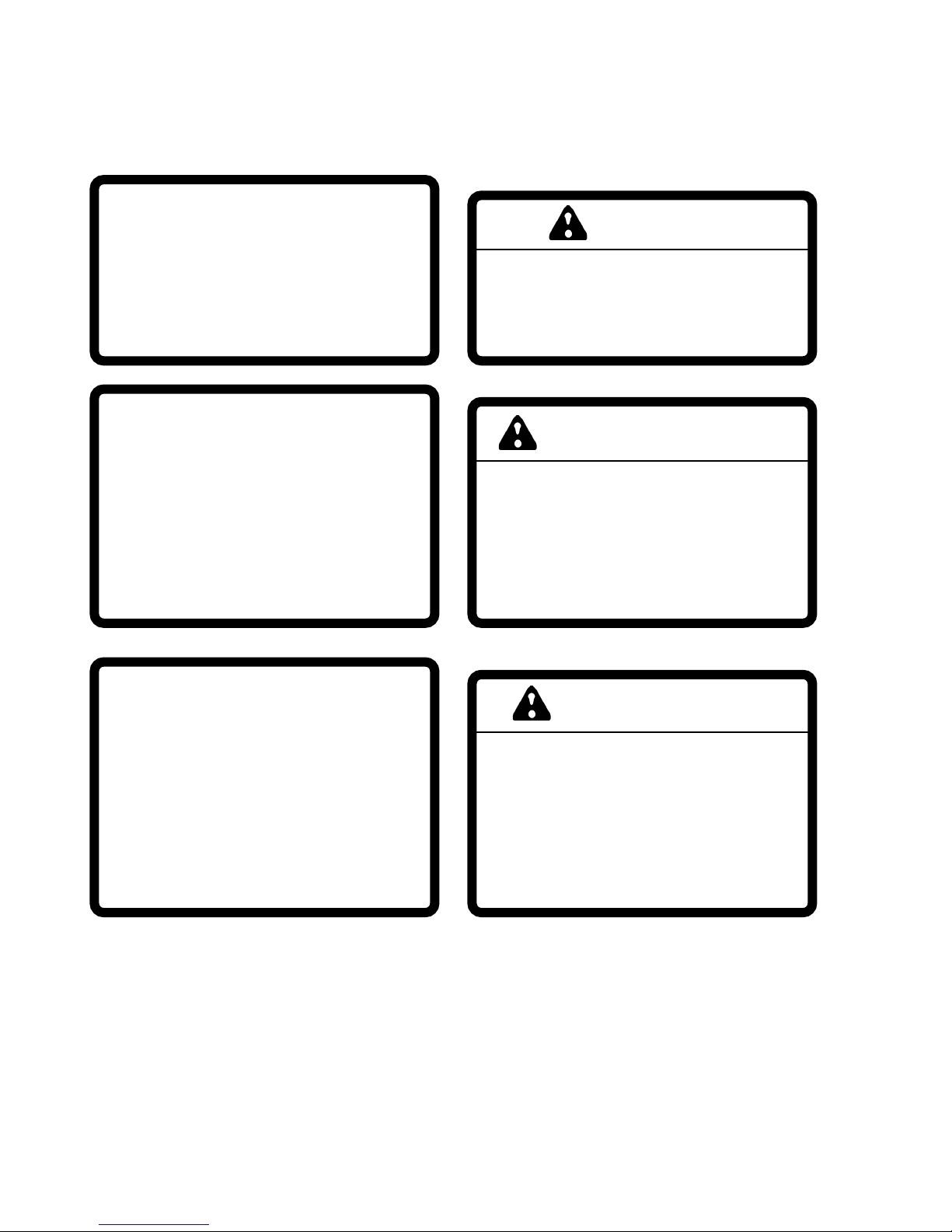
A full-floating rotary mower deck is designed to fit all Steiner power units with the quick hitch front lift.
Three sizes match the power unit to the application. These decks are easy to attach and detach allowing
interchange with the many other front mounted attachments. The side discharge rotary mower provides
even distribution of clippings while the full-floating deck follows the contours of the terrain for an even cut
with cutting height controlled by the front caster wheels and full width rear roller. The deck can be safely
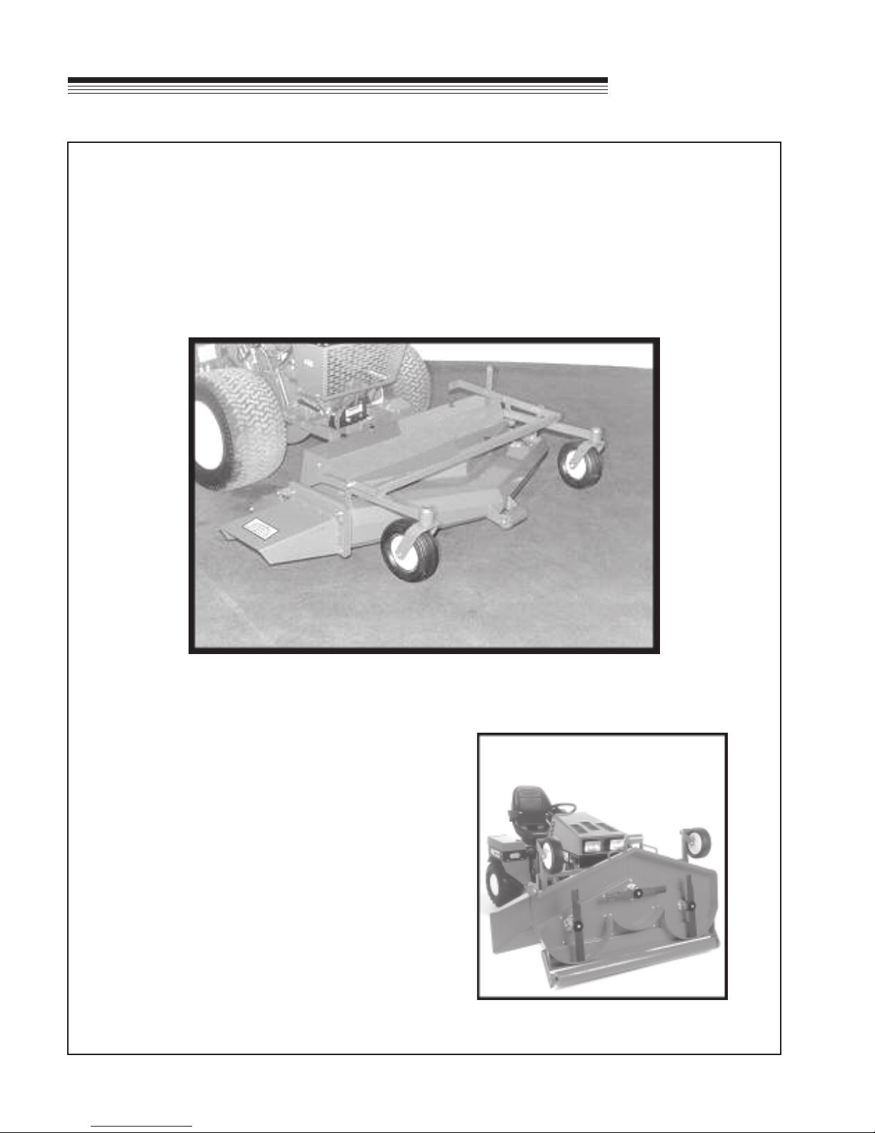
serviced and cleaned while still attached to the tractor. Convenient handles enable the deck to be lifted
vertically over 90 degrees so the blades are fully exposed. Exceptional visibility and maneuvering is
possible with this front mounted design mower.
NOTE: The flip-up deck feature was added
beginning with the following Serial Numbers:
75-70855 ----------------------- 1494
75-70860 ----------------------- 4728
75-70865 ----------------------- 1970
2
Page 5

ROTARY
SPECIFICATIONS
MOWER
SPECIFICATIONS
Model 75-70855 75-70860 75-70865
Overall Width with Chute: ......... 60-1/2" ......................... 73" ................................ 85"
Overall height:........................... 19" ............................... 19" ................................ 19"
Overall length:........................... 49-1/2" ......................... 48-3/4" ......................... 55"
Cutting Width: ...........................47" ............................... 59-3/8" ......................... 72"
Cutting Height: ..........................1" to 4-1/2". .................. 1" to 4-1/2" ...................1" to 4"
Blades: ...................................... 3 - 16-1/4" blades ........ 3 - 20-1/2" blades ........ 3 - 24-3/4" blades
Weight:...................................... 330 lbs. ........................ 360 lbs. ........................ 470 lbs.
3
Page 6
SAFETY
ROTARY
MOWER
NOTICE !!!
Unauthorized modifications may present extreme
safety hazards to operators and bystanders and
could also result in product damage.
Jacobsen, a Textron Company strongly warns
against, rejects and disclaims any modifications,
add-on accessories or product alterations that are
not designed, developed, tested and approved by
Jacobsen Engineering Department. Any Jacobsen
product that is altered, modified or changed in any
manner not specifically authorized after original
manufacture–including the addition of “after-market”
accessories or component parts not specifically
approved by Jacobsen–will result in the Jacobsen
Warranty being voided.
Any and all liability for personal injury and/or property
damage caused by any unauthorized modifications,
add-on accessories or products not approved by
Jacobsen will be considered the responsibility of
the individual(s) or company designing and/or
making such changes. Jacobsen will vigorously
pursue full indemnification and costs from any party
responsible for such unauthorized post-manufacture
modifications and/or accessories should personal
injury and/or property damage result.
This symbol means:
ATTENTION!
BECOME ALERT!
Your safety and the safety of others is involved.
Signal word definitions:
The signal words below are used to identify levels
of hazard seriousness. These words appear in this
manual and on the safety labels attached to
Jacobsen machines. For your safety and the safety
of others, read and follow the information given with
these signal words and/or the symbol shown above.
DANGER indicates an imminently hazardous
situation which, if not avoided, WILL result in death
or serious injury.
WARNING indicates a potentially hazardous
situation which, if not avoided, COULD result in
death or serious injury.
CAUTION indicates a potentially hazardous
situation which, if not avoided, MAY result in minor
or moderate injury. It may also be used to alert
against unsafe practices or property damage.
CAUTION used without the safety alert symbol
indicates a potentially hazardous situation which, if
not avoided, MAY result in property damage
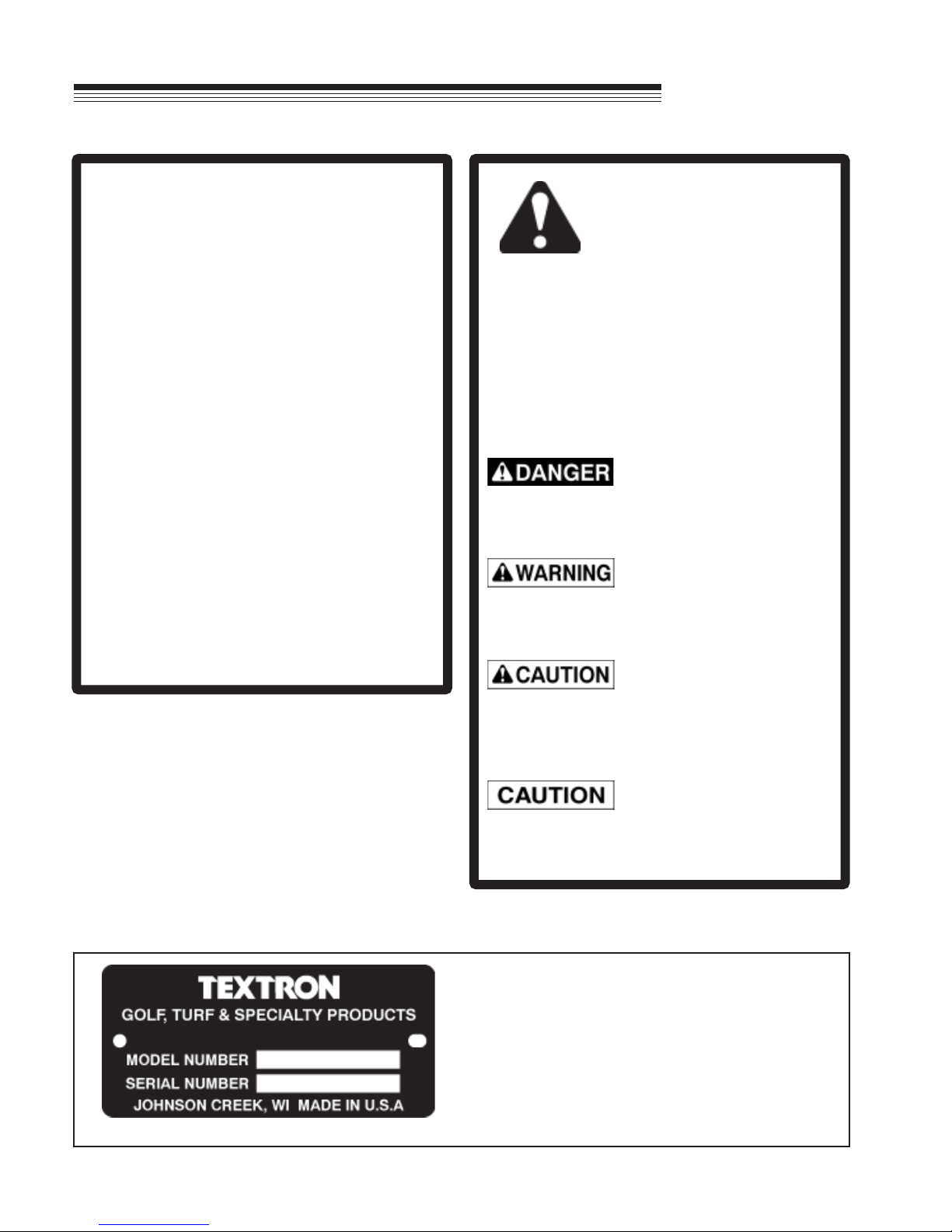
MODEL NUMBER: This number appears on
sales literature, technical manuals and price
lists.
SERIAL NUMBER: This number appears only
on your mower. It contains the model number
followed consecutively by the serial number.
Use this number when ordering parts or seeking
warranty information.
4
Page 7

ROTARY
SAFETY
MOWER
GENERAL SAFETY
1. Read and understand the Owner’s Manual before attempting to operate this machine.
2. Operate all controls from the operator’s seat, (if so equipped). NO RIDERS.
3. Keep all shields in place and safety switches adjusted properly.
4. Do not leave equipment unattended. Park on a level surface, set parking brake, STOP the engine and
remove the key.
5. Do not allow minors or the inexperienced to operate this machine.
6. Keep people and pets a safe distance away from machine using power driven attachments. Injury
could result from flying debris.
7. Do not attempt to work on unit or any attachments with engine running!
8. Wear all the necessary protective clothing and personal safety devices to protect your head, eyes,
ears, hands and feet. Operate the machine only in daylight or in good artificial light.
5
Page 8

SAFETY
ROTARY
MOWER
IMPORTANT
Safe Operation Practices for
Mowers
This cutting machine is capable of amputating
hands and feet and throwing objects. Failure to
observe the following safety instructions could
result in serious injury or death.
I GENERAL OPERATION
• Read, understand, and follow all instructions
in the manual and on the machine before
starting.
• Only allow responsible adults, who are
familiar with the instructions, to operate the
machine.
• Clear the area of objects such as rocks, toys,
wire, etc., which could be picked up and
thrown by the blade.
• Be sure the area is clear of other people
before mowing. Stop the machine if anyone
enters the area.
• Do not operate the machine while under the
influence of alcohol or drugs.
• Watch for traffic when operating near or
crossing roadways.
• Use extra care when loading or unloading the
machine into a trailer or truck.
• Always wear safety goggles or safety glasses
with side shields when operating mower.
II SLOPE OPERATION
Slopes are a major factor related to
loss-of-control and tip-over accidents, which can
result in severe injury or death. All slopes
require extra caution. If you feel uneasy on it, do
not mow it.
DO:
• Mow up and down slopes, not across.
• Remove obstacles such as rocks, tree limbs,
etc.
• Never carry passengers.
• Do not mow in reverse unless absolutely
necessary. Always look down and behind
before and while backing.
• Be aware of the mower discharge direction
and do not point it at anyone. Do not operate
the mower without the discharge chute in
place.
• Slow down before turning.
• Never leave a running machine unattended.
Always turn off blades, set parking brake, stop
engine, and remove keys before dismounting.
• Turn off blades when not mowing.
• Stop engine before unclogging discharge
chute.
• Mow only in good light, keeping away from
holes and hidden hazards.
• Watch for holes, ruts, or bumps. Uneven
terrain could overturn the machine. Tall grass
can hide obstacles.
• Use slow speed on slopes.
• Follow the manufacturers recommendations
for wheel weights or counterweights to
improve stability.
• Use extra care with grass catchers or other
attachments. These can change the stability
of the machine.
• Keep all movement on the slope slow and
gradual. Do not make sudden changes in
speed or direction.
• Avoid stopping or starting on a slope. If tires
lose traction, disengage the blades and
proceed slowly straight down the slope.
6
Page 9

ROTARY
MOWER
SAFETY
DO NOT:
• Do not turn on slopes unless necessary, and
then, turn slowly and gradually downhill, if
possible.
• Do not mow drop-offs, ditches, or
embankments. The mower could suddenly
turn over if a wheel is over the edge of a cliff
or ditch, or if an edge caves in.
• Do not mow on wet grass. Reduced traction
could cause sliding.
• Do not try to stabilize the machine by putting
your foot on the ground.
• Do not use grass catcher on steep slopes.
III CHILDREN
Tragic accidents can occur if the operator is not
alert to the presence of children. Children are
often attracted to the machine and the mowing
activity. Never assume that children will remain
where you last saw them.
IV SERVICE
• Use extra care in handling gasoline and other
fuels. They are flammable and the vapors are
explosive.
- Use only an approved container.
- Never remove gas cap or add fuel with
engine running. Allow engine to cool before
refueling.
- Do not smoke.
- Never add or drain fuel with machine
indoors.
- Never store the machine or fuel container
inside where there is an open flame, such
as in a water heater.
• Never run the machine in a closed area.
• Keep nuts and bolts, especially blade
attachment bolts, tight and keep equipment in
good condition.
• Never tamper with safety devices. Check their
proper operation regularly.
• Keep machine free of grass, leaves, and other
debris build-up. Clean up oil or fuel spillage.
Allow machine to cool before storing.
• Keep children out of the mowing area and
under the watchful eye of another responsible
adult.
• Be alert and turn machine off if children enter
the area.
• Before and when backing, look behind and
down for small children.
• Never carry children as passengers, even
with the blades off. They may suddenly fall
off and be seriously injured or interfere with
safe machine operation.
• Never allow children to operate the machine.
• Use extra care when approaching blind
corners, shrubs, trees, or other objects that
may obscure vision.
• Stop and inspect the equipment if you strike
an object. Repair, if necessary, before
re-starting.
• Never make adjustments or repairs with the
engine running.
• Discharge chute components are subject to
wear, damage, and deterioration, which could
expose moving parts or allow objects to be
thrown. Frequently check components and
replace with manufacturer’s recommended
parts, when necessary.
• Mower blades are sharp and can cut. Wrap
the blade(s) or wear gloves, and use extra
caution when servicing them.
• Check brake operation frequently (if
equipped). Adjust and service as required.
7
Page 10
DECALS
ROTARY
MOWER
Location:
On mower deck, front center.
8
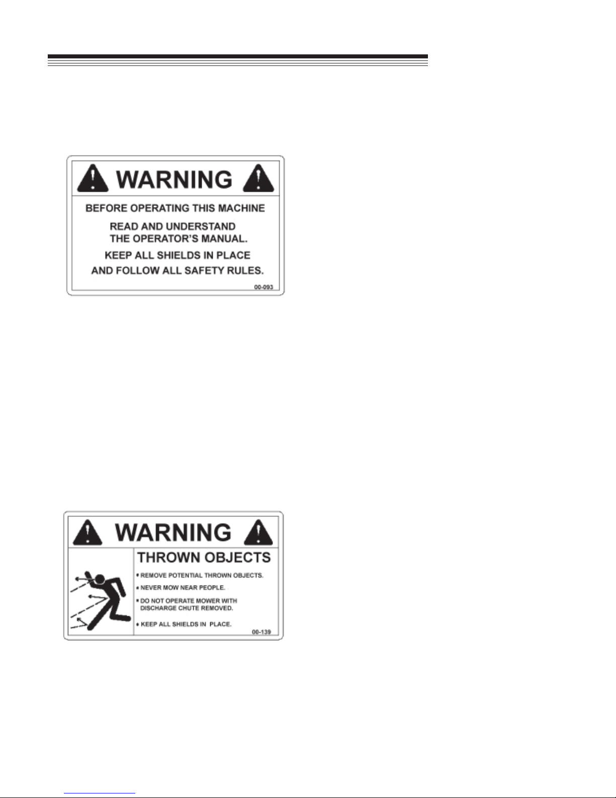
Location:
On mower deck and discharge chute.
Page 11

ROTARY
MOWER
DECALS
Location:
On mower deck top front center and both sides.
Location:
On mower deck top shield.
9
Page 12

ASSEMBLY INSTRUCTIONS
ROTARY
MOWER
1. Remove the mower from the shipping crate.
2. Remove top shield.
3. Install both left and right hitch arms as shown in Figure 7. Torque the 1/2" attaching bolts to 85 ft. lbs.
Serial Numbers:
75-70855: 1001-1493, 75-70860: 1001-4727, 75-70865: 1001-1969
Install the 1/2" locknut, which holds the two hitch arms together. Tighten and back off 1/2 turn. This
allows some independent movement of the hitch arms.
Serial Numbers:
75-70855: 1494 & Up, 75-70860: 4728 & Up, 75-70865: 1970 & Up
Install the 1/2" nut and the 1/2" lockwasher, which holds the two hitch arms together. Torque to 85 ft. lbs.
4. Be sure that the mower main drive belt is installed correctly on all pulleys. Check spring-loaded idler
arm position. Choose a mounting hole in the deck which allows the idler arm to lean toward the drive
shaft, with the spring attached. Fasten spring to chain and idler arm as shown on Page 16.
Serial Numbers:
75-70855: 1001-1493, 75-70860: 1001-4727, 75-70865: 1001-1969
Choose a chain link that stretches spring to an overall length of 8-9 inches.
Serial Numbers:
75-70855: 1494 & Up, 75-70860: 4728 & Up, 75-70865: 1970 & Up
Choose a chain link that stretches spring approximately 1" on 75-70860 or 1-1/2" on 75-70855 &
75-70865.
5. Check bolts mounting spindles to the deck. Torque should be 35-40 ft. lbs.
6. Check blade bolts. Torque should be 75 - 85 ft. lbs.
7. Check 1/4" cap screws on pulley bushings (Figure 1, Item 9). Torque should be 95 inch pounds.
Tighten these cap screws in alternating sequence 10-12 times to assure equal torque on all cap
screws.
8. Reinstall the top shield.
9. Remove 1/2" locknut on height adjustment lever and position correctly as shown on Page 12. Replace
locknut.
10. Remove the drive pulley shield and install the proper drive belt for the power unit. Replace shield.
11. Attach mower to power unit. See Page 11 for installation instructions. See Pages 6 & 7 for safety
instructions and Page 12 for operating instructions.
10
Page 13

ROTARY
MOWER
ATTACHING MOWER TO TRACTOR:
- Operate latch control to open hitch latches.
- Drive tractor into position aligning the quick hitch.
- Be sure both latches engage fully and and are placed in the locked position.
- Stop engine! Do not attempt to install drive belt with engine running.
- Release idler assembly to facilitate easy installation of the drive belt.
- Put belt over drive pulleys and engage or adjust idler assembly.
(See Power Unit Operator’s Manual for PTO belt tension adjustments.)
- Set mower to desired cutting height.
- Start engine and engage PTO slowly to prevent shock load on mower components.
INSTALLATION
- Mow with front lift lever in “FLOAT” position only.
REAR WEIGHT REQUIREMENTS
The table of requirements for rear weights is based upon average mowing conditions and operator’s weight
of 150 lbs. The recommendations may vary with the weight of the operator, other accessories, and the
mowing conditions. It is the operator’s responsibility to determine the correct amount of weight needed to
improve stability. All weights must be removed when the mower is removed. (See Caution in Power Unit
Operator’s manual.)
ledoMtinUrewoPkceD"84kceD"06kceD"27
032/022sthgiew0sthgiew0sthgiew2
014sthgiew2sthgiew4
034/024sthgiew2sthgiew4sthgiew5
tonsikcedsihT
dednemmocer
524sthgiew2sthgiew2sthgiew4
525sthgiew0sthgiew0sthgiew0
11
Page 14

OPERATION
Observe all safety decals.
Keep all shields in place. Do not operate mower with discharge chute removed.
Do not operate mower with other persons in the area. Irregularities in ground surface
can permit foreign material to be propelled from beneath deck to cause serious injury
or death.
Before leaving tractor, stop on a level surface, move Forward - Reverse control to
neutral position, disengage PTO, set parking brake, lower mower deck and stop
engine.
Remove key from ignition if maintenance procedures are to be performed or tractor is
to be left unattended.
OPERATING INSTRUCTIONS
ROTARY
MOWER
- Do not operate mower with discharge chute removed.
- Mow with front lift lever in “FLOAT” position only.
- Engage PTO slowly at low engine r.p.m.
- Mower is designed to operate at full throttle for mowing heavy turf, but 3/4 throttle is adequate for
average conditions. Set mower blade speed with throttle and control ground speed with Forward Reverse control.
- Use extreme caution when operating on hills. Mow up and down whenever possible.
- See Page 11 for weight recommendations.
SETTING MOWER CUTTING HEIGHT
- Lift mower deck off the ground and shut off tractor engine.
- Remove clevis pin at location A from height adjustment link.
- Raise or lower deck to desired height.
- Replace clevis pin into height adjustment link.
12
Page 15

ROTARY
MOWER
MAINTENANCE
Daily maintenance:
Visual inspection for loose parts and accumulation of grass and dirt.
Clean accumulation of grass clippings from beneath deck daily for better mowing performance.
Keep blades sharp. Check the tips of the blades for wear.
25 hour maintenance:
In addition to daily maintenance, grease roller and all bearings.
Spindle housings must be kept full of grease. Grease spindles until grease “shows” at the relief
hole under the spindle drive pulley.
NOTE: The relief hole is under the spindle hub and is not visible. As grease enters the spindle
housing you can hear the sound of escaping air at the relief hole. Stop greasing when the sound of
escaping air ceases.
SERVICE
Check drive belt tension. See Drive Belt Installation on Page 16.
Check 1/4" cap screws on pulley bushings. Torque should be 95 inch pounds. Tighten these cap
screws in alternating sequence 10-12 times to assure equal torque on all cap screws.
Check blade bolts. Torque should be 75-85 ft. lbs.
Annual Maintenance:
In addition to daily and 25 hour maintenance, remove the drive belt and check for cracks or wear.
Rotate each spindle to check for roughness which would indicate bearing wear. Remove and
sharpen blades, clean and wash deck prior to storage. The acid in grass clippings causes
premature corrosion and rusting of mower parts.
Grease all bearings after washing.
13
Page 16

SERVICE
ROTARY
MOWER
ADJUSTMENTS
Sharpening blades
Be careful while sharpening blades that the corners of the blade do not become rounded at the tips. This
reduces the blades overlap and will cause skipping. While sharpening, it is essential to ensure the balance
of the blades is maintained to prevent vibration. Blade bolt torque should be 75-85 ft. lbs. Rotate blades
after re-installing to check for bent or bowed blades and blade alignment.
Blade alignment
When installing sharpened blades or new blades be sure the mating surfaces are clean and the retaining
washer is not bent. Check for bent blades by rotating blades until tips are near each other. (It is easier to
do this with main drive belt idler spring unhooked.)
Leveling mower deck
The front to rear leveling adjustment is provided by two slots in the linkage which supports the front of the
deck. This allows each side to be adjusted independently. Check the blade level with mower resting on a
level floor and the cutting height set at about 2-1/2" setting. Measure to the tip of the left blade at the rear,
then rotate the blade 180 degrees and measure again to the tip of the blade at the front. The cutting height
should be equal or 1/16" lower at the front. Change adjustment in the left slot as required and measure
again until proper setting is reached. Repeat procedure for blade at right end of the deck and adjust right
slot.
14
Page 17

ROTARY
SERVICE
MOWER
TO REMOVE BELT:
Serial Numbers:
75-70855 1001-1493
75-70860 1001-4727
75-70865 1001-1969
Remove top shield and the bolts which fasten the hitch arms to the deck brackets. No further disassembly
is necessary.
Serial Numbers:
75-70855 1494 & Up
75-70860 4728 & Up
75-70865 1970 & Up
Remove the six 1/4" X 3/4" bolts from the flip-up braces and remove the pivot stop pin and the idler spring.
Remove the braces.
• With the idler spring released, move the idler toward the drive shaft.
• Slip belt off the outer spindle pulleys.
• Slip belt off the front center idler and spindle.
• Remove belt.
15
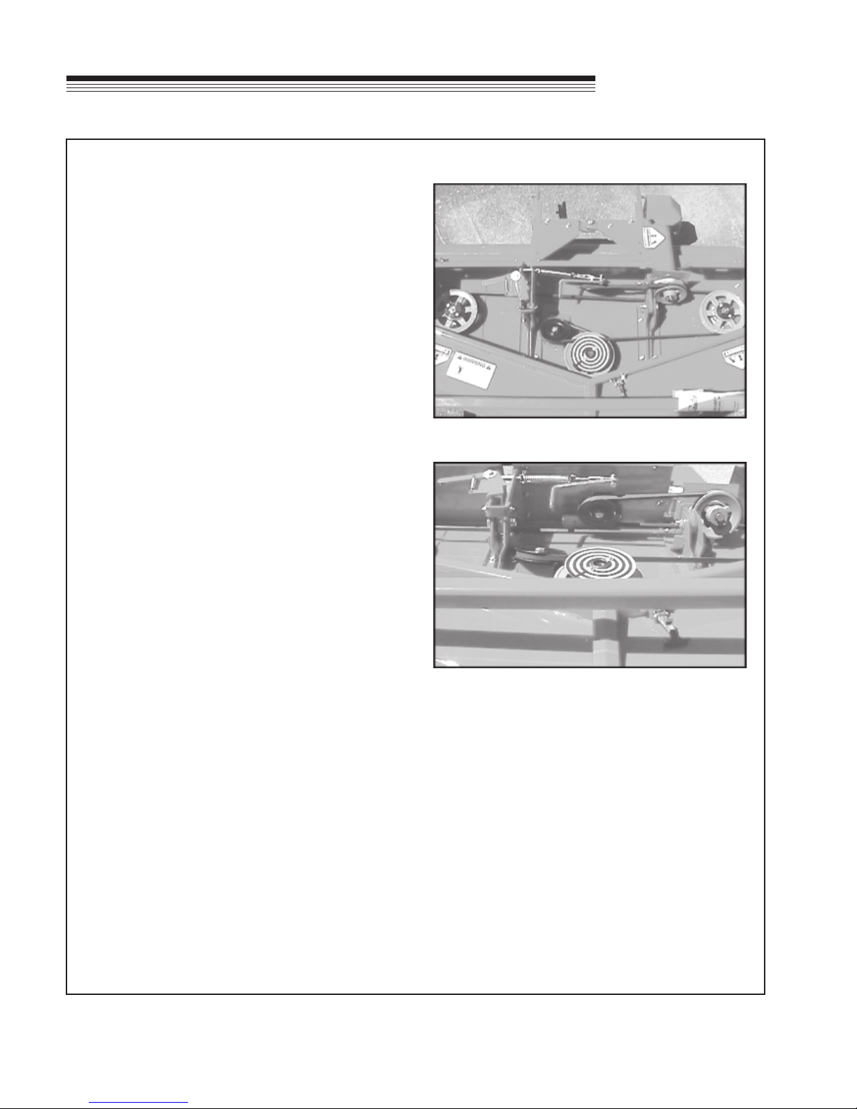
Page 18
SERVICE
TO INSTALL BELT:
• Form loop for drive pulley and idler pulley as
shown. (Photos 2 & 3)
• Slip loop over drive pulley on left hitch arm.
(Photos 2 & 3)
• Form a loop around the center spindle
pulley and fixed idler pulley. (Photos 2 & 3)
• Position belt on the outer spindle pulleys.
(Photos 2 & 3)
Serial Numbers:
75-70855 1001-1493
75-70860 1001-4727
75-70865 1001-1969
ROTARY
MOWER
PHOTO 2
Re-install hitch arms and bushings in place .
Serial Numbers:
75-70855 1494 & Up
75-70860 4728 & Up
75-70865 1970 & Up
Re-install hitch arms and pivot braces. Torque 1/2"
attaching bolts to 85 ft. lbs. (Photos 2 & 3)
Hook idler spring in place.
Serial Numbers:
75-70855 1001-1493
75-70860 1001-4727
75-70865 1001-1969
Choose chain link that stretches spring to an overall
length of 8-9 inches.
Serial Numbers:
75-70855 1494 & Up
75-70860 4728 & Up
75-70865 1970 & Up
PHOTO 3
Choose chain link which stretches spring
approximately one inch on 75-70860 or 1-1/2" on
75-70855 & 75-70865.
• Re-install top shield.
16
Page 19

ROTARY
SERVICE
MOWER
USING THE FLIP-UP OPTION ON THE 75-70855, 75-70860 AND 75-70865 ROTARY MOWERS
1. Stop on a level surface, set parking brake and shut off the tractor.
2. Lift the deck.
3. Remove the top deck shield and set aside.
4. Standing at the front of the deck, pull the handle on the idler arm so the belt comes loose.
5. Remove the belt from the drive pulley.
6. Remove the presto pin and slide pin from holes.
7. Grasp the handles and lift the deck up and back until you hear a click. This indicates that the latch has
engaged.
8. Lower the deck until the roller touches the ground. This gives stability when working on the deck.
9. Complete your work under the deck.
10. Start the tractor and lift the deck again. Shut off the tractor.
11. Grasp the handles at the front of the deck. Push the deck back slightly and release the catch.
12. Pull the deck forward and down, keeping a firm grip on the handles.
13. Lower the deck to the ground.
14. Replace the pin and clip in the hole above the lift arm.
15. Grasp the idler arm handle again and pull to stretch the spring. Place the belt onto the drive pulley.
16. Make sure the belt is around all pulleys. Release the idler arm.
17. Replace the top shield and secure with the rubber latches.
18. Moving the power unit with the deck in the flipped up position is not recommended. Serious injury and
or damage could result.
17
Page 20
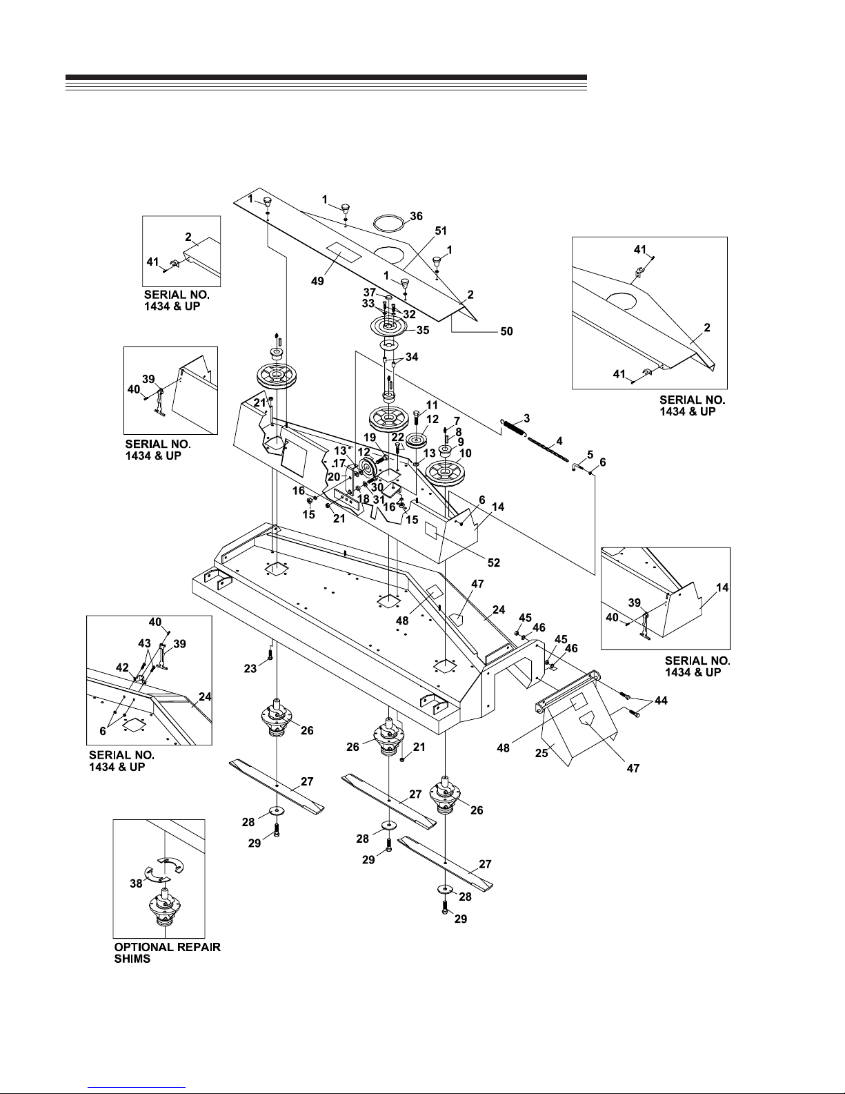
DECK PARTS 48"
ROTARY
FIGURE 1
MOWER
18
Page 21

ROTARY
DECK PARTS 48"
MOWER
ITEM PART NO. DESCRIPTION QTY
1-1 47-050 KNOB 4
64002-04 LOCKWASHER, EXT. 5/16 4
(SN 1001 - 1433)
1-2 60-535 SHIELD-TOP 1
(SN 1001 - 1009)
60-567 SHIELD-TOP DECK 1
(SN 1010 - 1433)
60-652 SHIELD-TOP DECK 1
(SN 1434 - )
1-3 41-052 SPRING-EXT 0.875 X 6.750 1
1-4 6107645 CHAIN, IDLER ARM STOP 1
(SN 1001 - 1577)
1-5 64-534 HOOK-SPRING 1
(SN 1001 - 1577)
1-6 64141-2 NUT-WLF 1/4-20 4
1-7 29-010 GREASE FITTING-1/4 3
1-8 64164-12 KEY-1/4X1/4X1 SQ END 3
1-9 83-H16SPL BUSHING-H X 1" SPLIT TYPE3
1-10 83-BK50H PULLEY-5" H1 BUSHING 3
1-11 64123-117 BOLT-HEX 1/2-13X1-1/2 1
1-12 83-012 IDLER-"V" 1/2" ID X 4-1/2" OD 2
1-13 99-B12 WASHER-1/4 X 17/32 X 1-1/8 2
1-14 62-723 DECK-TOP 1
(SN 1001 - 1433)
62-843 DECK-TOP 1
(SN 1434 - 1577)
62-872 UPR DK WLDMT 1
(SN 1578 - )
1-15 64025-09 HEX, NUT 1/2-13 2
1-16 64006-05 LOCKWSHR-HELICAL 1/2 2
1-17 64163-67 WASHER-.516X1X12GA 1
1-18 85-B29 BUSHING-.406 X .740 X .258 1
1-19 90-0814 BOLT-1/2 X 1-3/4 1
1-20 40-290 IDLER ARM 1
(SN 1001 - 1577)
40-329.7 IDLER ARM 1
(SN 1578 - )
1-21 64141-4 NUT-WLF 3/8-16 18
1-22 64139-18 BLT-WLF 3/8-16X1-1/4 12
1-23 64139-21 BLT-WLF 3/8-16X3/4 5
1-24 62-716 DECK-MOWER 1
(SN 1001 - 1433)
62-844 DECK-MOWER 1
(SN 1434 - )
1-25 60-534 CHUTE-SIDE DISCHARGE 1
1-26 87-143 SPINDLE 3
1-27 79-062 BLADE-16-1/4" .700 AIR LIFT 3
79-064 BLADE-16-1/4" 1-3/8 AIR LIFT3
(OPTIONAL)
1-28 99-B14 WASHER-1/4 X 1/2 ID X 3 OD3
1-29 91-0810 BOLT-1/2 X 1-1/4 NF 3
FIGURE 1
ITEM PART NO. DESCRIPTION QTY
1-30 64123-50 BOLT-HEX 3/8-16X1 1
1-31 64-799 WASHER-13/32 X 1-9/32 1
1-32 99-K38 BOLT-1/4 X 1-1/4 BH 2
(SN 1010 - )
1-33 64163-03 WSHR-.256IDX.62ODX18 2
(SN 1010 - )
1-34 64-687.7 SPACER 2
(SN 1010 - )
1-35 00-137 DECAL-SPIRAL INDICATOR 1
(SN 1010 - )
60-568 SUPPORT 1
(SN 1010 - )
1-36 56-059-17 TRIM-LOC-RUBBER 17" 1
(SN 1010 - )
1-37 06-010 CAP PLUG-1" 1
(SN 1010 - )
1-38 64-866 SHIM-SPINDLE 22 GA. 1
(1 PAIR OPTIONAL)
64-867 SHIM-SPINDLE 16 GA. 1
(1 PAIR OPTIONAL)
64-868 SHIM-SPINDLE 12 GA. 1
(1 PAIR OPTIONAL)
1-39 47-090 LATCH-RUBBER 3" LONG 3
(SN 1434 - )
1-40 04-008 POP RIVET-1/8 X 1/4 SS 6
(SN 1434 - )
1-41 04-007 POP RIVET-1/8 X 1/8 SS 6
(SN 1434 - )
1-42 64-900.7 BRKT-TOP SHIELD LATCH 1
(SN 1434 - )
1-43 64139-02 BLT-WLF 1/4-20X1/2 2
(SN 1434 - )
1-44 64123-15 BOLT-3/8-16X3/4 3
1-45 64025-05 NUT-3/8-16 3
1-46 64006-03 LOCKWASHER-3/8 3
1-47 00-092 DECAL-HANDS & FEET 2
1-48 00-139 DECAL-WARNING 2
1-49 00-138 DECAL-DANGER 1
1-50 00-129 DECAL-BELT INSTALL 1
(LOCATED UNDERNEATH TOP SHIELD)
1-51 4128363 DECAL-STEINER LOGO 1
1-52 00-140 DECAL-ANSI CERT. 1
1-53* 00-093 DECAL 1
1-54* 4112761 LABEL-MADE IN USA 1
* NOT ILLUSTRATED
19
Page 22

DECK PARTS 60"
ROTARY
FIGURE 2
MOWER
20
Page 23

ROTARY
DECK PARTS 60"
MOWER
ITEM PART NO. DESCRIPTION QTY
2-1 47-050 KNOB 4
64002-04 LOCKWASHER, EXT. 5/16 4
(SN 1001 - 4188)
2-2 60-526 SHIELD-TOP DECK 1
(SN 1001 - 1224)
60-544 SHIELD-TOP DECK 1
(SN 1225 - 4188)
4133299.17 SHIELD-TOP DECK 1
(SN 4189 - )
2-3 41-052 SPRING-EXT 0.875 X 6.750 1
2-4 6107645 CHAIN, IDLER ARM STOP 1
(SN 1001 - 1577)
2-5 64-534 HOOK-SPRING 1
(SN 1001 - 1577)
2-6 64141-2 NUT-WLF 1/4-20 4
2-7 29-010 GREASE FITTING-1/4 3
2-8 64164-12 KEY-1/4X1/4X1 SQ END 3
2-9 83-H16SPL BUSHING-H X 1" SPLIT TYPE 3
2-10 83-BK72H SHEAVE- BK72H 3
2-11 64123-117 BOLT-HEX 1/2-13X1-1/2 1
2-12 83-012 IDLER-"V" 1/2" ID X 4-1/2" OD 2
2-13 99-B12 WASHER-1/4 X 17/32 X 1-1/8 2
2-14 62-700 DECK-TOP 1
(SN 1001 - 1194)
62-729 DECK-TOP 1
(SN 1195 - 4188)
62-835 DECK-TOP 1
(SN 4189 - 5456)
62-868.7 UPR DK WLDMT 1
(SN 5457 - )
2-15 64025-09 HEX, NUT 1/2-13 2
2-16 64006-05 LOCKWSHR-HELICAL 1/2 2
2-17 64163-67 WASHER-.516X1X12GA 1
2-18 85-B29 BUSHING-.406 X .740 X .258 1
2-19 90-0814 BOLT-1/2 X 1-3/4 1
2-20 40-289 IDLER ARM 1
(SN 1001 - 1194)
40-290 IDLER ARM 1
(SN 1195 - 5456)
40-329.7 IDLER ARM 1
(SN 5457 - )
2-21 64141-4 NUT-WLF 3/8-16 18
2-22 64139-18 BLT-WLF 3/8-16X1-1/4 12
2-23 64139-21 BLT-WLF 3/8-16X3/4 5
2-24 62-694 DECK-MAIN 1
(SN 1001 - 1194)
62-727 DECK-MAIN 1
(SN 1195 - 4188)
62-834.17 DECK-MAIN 1
(SN 4189 - )
FIGURE 2
ITEM PART NO. DESCRIPTION QTY
2-25 62-696.17 CHUTE-SIDE DISCHARGE 1
2-26 87-143 SPINDLE-MOWER 3
2-27 79-050 BLADE-20-1/2" .700 AIR LIFT 3
79-053 BLADE-20-1/2" 1-3/8 AIR LIFT3
2-28 99-B14 WASHER-1/4 X 1/2 ID X 3 OD3
2-29 91-0810 BOLT-1/2 X 1-1/4 NF 3
2-30 64123-50 BOLT-HEX 3/8-16X1 1
2-31 64-799 WASHER-13/32 X 1-9/32 1
2-32 99-K38 BOLT-1/4 X 1-1/4 BH 2
(SN 1225 - )
2-33 64163-03 WSHR-.256IDX.62ODX18 2
(SN 1225 - )
2-34 64-687.7 SPACER 2
(SN 1010 - )
2-35 00-137 DECAL-SPIRAL INDICATOR 1
(SN 1225 - )
60-568.7 SUPPORT 1
(SN 1010 - )
2-36 56-059-17 TRIM-LOC-RUBBER 17" 1
(SN 1225 - )
2-37 06-010 CAP PLUG-1" 1
(SN 1225 - )
2-38 64-866 SHIM-SPINDLE 22 GA. 1
(1 PAIR OPTIONAL)
64-867 SHIM-SPINDLE 16 GA. 1
(1 PAIR OPTIONAL)
64-868 SHIM-SPINDLE 12 GA. 1
(1 PAIR OPTIONAL)
2-39 47-090 LATCH-RUBBER 3" LONG 3
(SN 4189 - )
2-40 04-008 POP RIVET-1/8 X 1/4 SS 6
(SN 4189 - )
2-41 04-007 POP RIVET-1/8 X 1/8 SS 6
(SN 4189 - )
2-42 64-900.7 BRCKT-TOP SHIELD LATCH 1
(SN 4189 - )
2-43 64139-02 BLT-WLF 1/4-20X1/2 2
(SN 4189 - )
2-44 64123-15 BOLT-3/8-16 X 3/4 3
2-45 64025-05 NUT-3/8-16 3
2-46 64006-03 LOCKWASHER-3/8 3
21
Page 24

DECK PARTS 72"
ROTARY
FIGURE 3
MOWER
22
Page 25

ROTARY
DECK PARTS 72"
MOWER
ITEM PART NO. DESCRIPTION QTY
3-1 47-050 KNOB 4
64002-04 LOCKWASHER, EXT. 5/16 4
(SN 1001 - 1837)
3-2 60-540.17 SHIELD-TOP DECK 1
(SN 1001 - 1016)
60-545.17 SHIELD-TOP DECK 1
(SN 1017 - 1837)
4133301.17 SHIELD-TOP DECK 1
(SN 1838 - )
3-3 41-051 SPRING-EXT 1.0 X 6.750 1
3-4 56-055-22 CHAIN-IDLER 1
(SN 1001 - 2301)
3-5 64-534 HOOK-SPRING 1
(SN 1001 - 2301)
3-6 64141-2 NUT-WLF 1/4-20 4
3-7 29-010 GREASE FITTING-1/4 3
3-8 64164-12 KEY-1/4X1/4X1 SQ END 3
3-9 83-H16SPL BUSHING-H X 1" SPLIT TYPE 3
3-10 83-BK80H PULLEY- BK80H 3
3-11 64123-70 BOLT-HEX 3/8-16X1-1/2 1
3-12 83-034 IDLER-"V" 3/8" ID X 5" OD 2
3-13 64163-61 WSHR .81X.406X16GA 5
3-14 62-733 DECK-TOP 1
(SN 1001 - 1837)
62-840.7 DECK-TOP 1
(SN 1838 - 2301)
62-873.7 UPR DK WLDMT 1
(SN 2302 - )
3-15 64141-4 NUT-WLF 3/8-16 22
3-16 64-900 BRKT-TOP SHIELD LATCH 2
(SN 1838 - )
3-17 04-007 POP RIVET-1/8 X 18 SS 8
(SN 1838 - )
3-18 85-B29 BUSHING-.406X.740X.258 1
3-19 64123-87 BOLT-HEX 3/8-16X1-3/4 1
3-20 40-292 IDLER ARM 1
(SN 1001 - 2301)
40-329 IDLER ARM 1
(SN 2302 - )
3-21 64139-02 BLT-WLF 1/4-20X1/2 4
(SN 1838 - )
3-22 64139-18 BLT-WLF 3/8-16X1-1/4 12
3-23 64139-21 BLT-WLF 3/8-16X3/4 7
3-24 62-730.17 DECK-MOWER 1
(SN 1001 - 1837)
62-841.17 DECK-MOWER 1
(SN 1838 - )
3-25 60-54117 CHUTE-SIDE DISCHARGE 1
3-26 87-143 SPINDLE 3
FIGURE 3
ITEM PART NO. DESCRIPTION QTY
3-27 79-068 BLADE-24-3/4" .700 AIR LIFT 3
79-069 BLADE-24-3/4" 1-3/8 AIR LIFT3
(OPTIONAL)
3-28 99-B14 WASHER-1/4X1/2IDX3OD 3
3-29 91-0810 BOLT-1/2 X 1-1/4 NF 3
3-30 64123-50 BOLT-HEX 3/8-16X1 1
3-31 64-799 WASHER-13/32 X 1-9/32 1
3-32 99-K39 BOLT-1/4 X 1-1/2 BH 2
(SN 1017 - )
3-33 453023 FLATWASHER, 1/4 4
(SN 1017 - )
3-34 64-688.7 SPACER 2
(SN 1017 - )
3-35 00-137 DECAL-SPIRAL INDICATOR 1
(SN 1017 - )
60-568.7 SUPPORT 1
(SN 1010 - )
3-36 56-059-17 TRIM-LOC-RUBBER 17" 1
(SN 1017 - )
3-37 06-010 CAP PLUG-1" 1
(SN 1017 - )
3-38 64-866 SHIM-SPINDLE 22 GA. 1
(1 PAIR OPTIONAL)
64-867 SHIM-SPINDLE 16 GA. 1
(1 PAIR OPTIONAL)
64-868 SHIM-SPINDLE 12 GA. 1
(1 PAIR OPTIONAL)
3-39 47-090 LATCH-RUBBER 3" LONG 3
(SN 1838 - )
3-40 04-007 POP RIVET, 1/8 X 1/4 SS 6
(SN 1838 - )
3-41 64123-15 BOLT-3/8-16 X 3/4 3
3-42 64025-05 NUT-3/8-16 3
3-43 64006-03 LOCKWASHER-3/8 3
23
Page 26
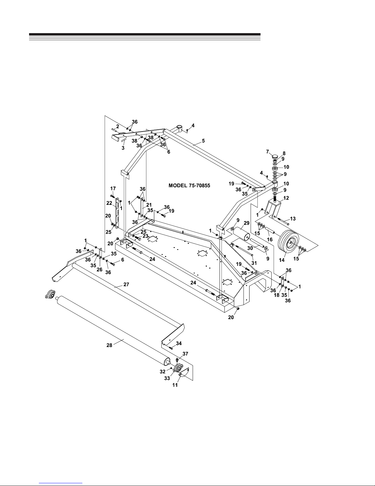
FRAME PARTS 48"
ROTARY
FIGURE 4
MOWER
24
Page 27

ROTARY
FRAME PARTS 48"
MOWER
ITEM PART NO. DESCRIPTION QTY
4-1 64141-4 NUT-WLF 3/8-16 13
4-2 03-0610 CLEVIS PIN-3/8 X 1-1/4 1
4-3 02-PP0318 PRESTO PIN-3/32 X 2-5/16 1
4-4 29-010 GREASE FITTING-1/4 2
4-5 62-725.7 FRAME-HEIGHT ADJ 1
4-6 64123-70 BOLT-HEX 3/8-16X1-1/2 5
4-7 53-060 HUB CAP-FOR MOWER 2
4-8 99-AC12NFLOCKNUT-CENTER 3/4 NF 2
4-9 64163-06 WASHER-.768/.756X1.25X14 12
4-10 55-Z9504AB BALL BEARING-3/4 ID 4
4-11 64-807 SPACER 2
(SN 1001 -11310)
64-845.7 SHIELD-BEARING 2
(SN 1311 - )
4-12 4132783.7 CASTER, MOWER 2
4-13 64123-93 BLT-HEX 3/8-16X5 2
4-14 53-104 WHEEL-CASTER 2
(SN 1001 - 1711)
55-G527 BEARING-BALL 2
55-107 BEARING-5/8 ID X 1-3/8 OD 2
(OPT HD)
53-186 WHEEL-10.25 X 3.25 2
(SN 1712 - )
55-112 BRG-ROLLER 5/8 ID X 1-3/8 1
53-187 RETAINER 2
FIGURE 4
ITEM PART NO. DESCRIPTION QTY
4-28 50-078.7 ROLLER-REAR 1
4-29 50-105 ROLLER-FRONT 1
85-B11 BEARING-3/4" WOOD RLR 2
4-30 50-074 AXLE-ANTI SCALP ROLLER 1
4-31 64123-219 BOLT-HEX 3/8-16X6 1
4-32 64141-6 NUT, 5/16-18 4
4-33 55-FB16016 BEARING-160 FLANGE 1" 2
4-34 64018-15 BLT-CRG 5/16-18X1 4
90-0510 BOLT-5/16 X 1-1/4 4
(SN 1001 - 1118)
99-K62 BOLT-FLANGE 5/16 X 1-1/4 4
(SN 1578 - )
4-35 64-663 BUSHING-ADJUSTER LINK 5
4-36 64-799 WASHER-13/32 X 1-9/32 18
4-37 29-045 GREASE FITTING-1/4 45 1
4-38 64-662 BUSHING-ADJUSTER LINK 2
4-15 64163-16 WASHER-41/64X1, 3/8X12GA12
4-16 50-062 AXLE TUBE-CASTER WHL 2
4-17 64139-21 BLT-WLF 3/8-16X3/4 1
4-18 42-440.7 LINK-RIGHT LIFT 1
4-19 64123-16 BLT-HEX 3/8-16X1-1/4 3
4-20 64229-05 LOCKNUT, 1/2-13 NYLON 3
4-21 42-445.7 LINK-LEFT FRONT 1
4-22 42-443.7 LINK-HEIGHT ADJUSTMENT 1
4-23 64123-117 BOLT-HEX 1/2-13X1-1/2 1
4-24 90-0832 BOLT-1/2-13 X 4 2
4-25 64163-67 WASHER-.516X1X12GA 2
4-26 42-442 LINK-MIDDLE 1
4-27 62-724 FRAME-REAR ROLLER 1
(SN 1001 - 1577)
62-869.7 FRAME-REAR ROLLER 1
(SN 1578 - )
25
Page 28

FRAME PARTS 60"
ROTARY
FIGURE 5
MOWER
26
Page 29

ROTARY
FRAME PARTS 60"
MOWER
ITEM PART NO. DESCRIPTION QTY
5-1 64141-4 NUT-WLF 3/8-16 10
5-2 03-0610 CLEVIS PIN-3/8 X 1-1/4 1
5-3 02-PP0318 PRESTO PIN-3/32 X 2-5/16 1
5-4 29-010 GREASE FITTING-1/4 2
5-5 62-695 FRAME-TUBE 1
(SN 1001 - 1194)
62-726.7 FRAME-TUBE 1
(SN 1195 - )
5-6 64123-70 BOLT-HEX 3/8-16X1-1/2 3
5-7 53-060 HUB CAP-FOR MOWER 2
5-8 99-AC12NFLOCKNUT-CENTER 3/4 NF 2
5-9 64163-06 WASHER-.768/.756X1.25X14 12
5-10 55-Z9504AB BALL BEARING-3/4 ID 4
5-11 64-807 SPACER 2
(SN 1001 - 3246)
64-845 SHIELD-BEARING 2
(SN 3247 - )
5-12 4132783.7 CASTER, MOWER 2
5-13 90-0640 BOLT,3/8-16 X 5 2
5-14 53-104 WHEEL-10.25X3.25 CASTER 2
(SN 1001 - 6813)
55-G527 BRG-BALL F/53-104 WHL 2
55-107 BEARING-5/8 ID X 1-3/8 OD 2
OPT HD)
53-186 WHEEL-10.25X3.25 CASTER 2
(SN 6814 - )
55-112 BRG-ROLLER 5/8 ID X 1-3/8 1
53-187 RETAINER-FLANGED 2
5-15 64163-16 WASHER-41/64X1, 3/8X12GA12
5-16 50-062 AXLE TUBE-CASTER WHL 2
5-17 64-799 WASHER-13/32 X 1-9/32 18
5-18 42-428 LINK-RIGHT 1
(SN 1001 - 1194)
42-444.7 LINK-RIGHT 1
(SN 1195 - )
FIGURE 5
ITEM PART NO. DESCRIPTION QTY
5-23 64123-117 BOLT-HEX 1/2-13X1-1/2 1
5-24 90-0832 BOLT-1/2 X 4 2
5-25 64163-67 WASHER-.516X1X12GA 2
5-26 42-429 LINK-MID LEFT 1
(SN 1001 - 1194)
42-446.7 LINK-MID LIFT 1
(SN 1195 - )
5-27 62-697 FRAME-ROLLER 1
(SN 1001 - 1194)
62-728 FRAME-REAR ROLLER 1
(SN 1195 - 5456 )
62-870.7 FRAME-REAR ROLLER 1
(SN 5457 - )
5-28 50-067 ROLLER-REAR 1
(SN 1001 - 1194)
50-079.7 ROLLER-REAR 1
(SN 1195 - )
5-29 50-105 ROLLER-FRONT 1
85-B11 BEARING-3/4" WOOD RLR 2
5-30 50-074 AXLE-ANTI SCALP ROLLER 1
5-31 64123-219 BOLT-HEX 3/8-16X6 1
5-32 64141-6 NUT, 5/16-18 4
5-33 55-FB16016 BEARING-160 FLANGE 1" 2
5-34 64018-15 BLT-CRG 5/16-18X1 4
(SN 1001 - 2010)
64123-47 BLT-HEX 5/16-18X1-1/4 4
(SN 2011 - 5456)
99-K62 BOLT-FLANGE 5/16 X 1-1/4 4
(SN 5457 - )
99-K62 BOLT-FLANGE 5/16 X 1-1/4 4
(SN 1578 - )
5-35 64-663 BUSHING-ADJ LINK THIN 6
(SN 1195 - )
5-19 64123-16 BLT-HEX 3/8-16X1-1/4 3
5-20 64229-05 LOCKNUT, 1/2-13 NYLON 3
5-21 42-427 LINK-LEFT FRONT 1
(SN 1001 - 1194)
42-445.7 LINK-LEFT FRONT 1
(SN 1195 - )
5-22 42-430 LINK-HEIGHT ADJUST 1
(SN 1001 - 1194)
42-447.7 LINK-HEIGHT ADJUST 1
(SN 1195 - )
5-36 64123-87 BOLT-HEX 3/8-16X1-3/4 1
5-37 29-045 GREASE FITTING-1/4 45 1
5-38 64-662 BUSHING-ADJ LINK THICK 2
(SN 1195 - )
5-39 64139-21 BLT-WLF 3/8-16X3/4 1
27
Page 30
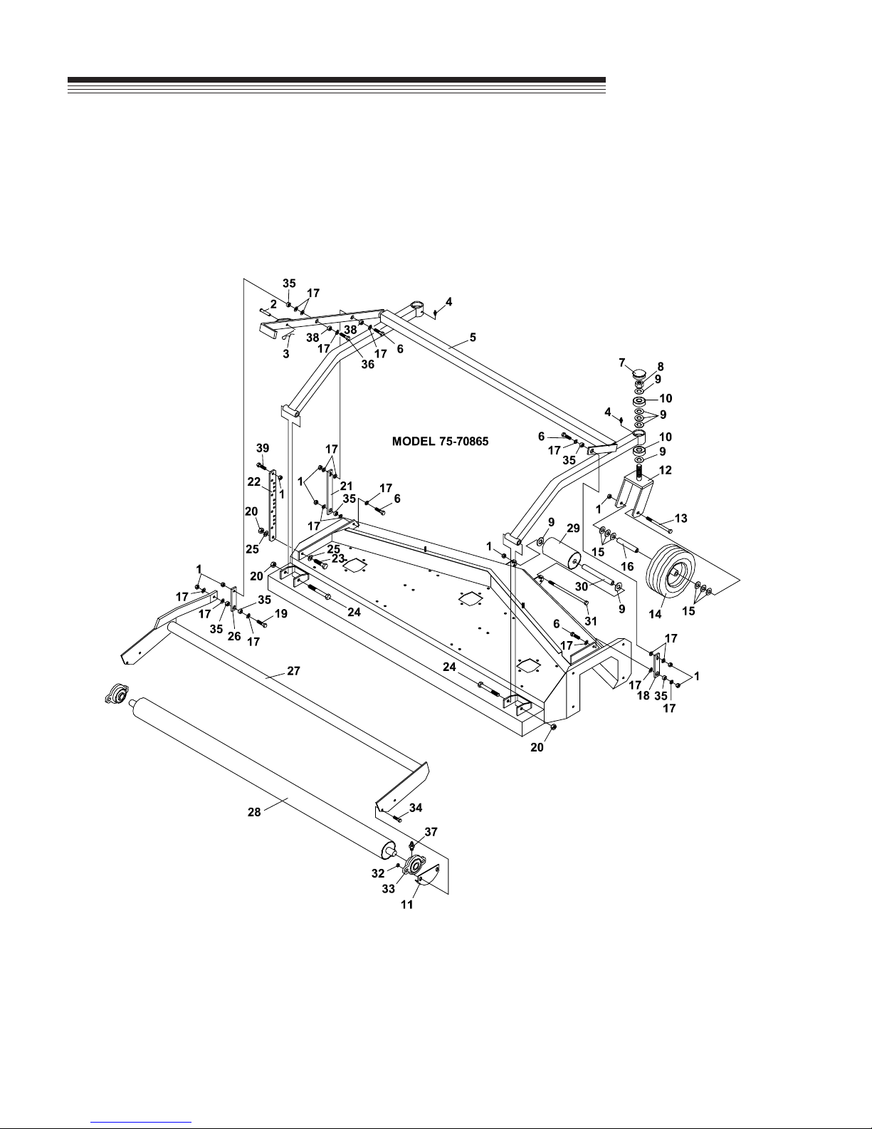
FRAME PARTS 72"
ROTARY
FIGURE 6
MOWER
28
Page 31

ROTARY
FRAME PARTS 72"
MOWER
ITEM PART NO. DESCRIPTION QTY
6-1 64141-4 NUT-WLF 3/8-16 10
6-2 03-0610 CLEVIS PIN-3/8 X 1-1/4 1
6-3 02-PP0318 PRESTO PIN-3/32 X 2-5/16 1
6-4 29-010 GREASE FITTING-1/4 2
6-5 62-731.7 FRAME-TUBE 1
6-6 99-K75 BOLT-HEX 3/8-16X1-1/2 4
6-7 53-060 HUB CAP-FOR MOWER 2
6-8 99-AC12NFLOCKNUT-CENTER 3/4 NF 2
6-9 64163-06 WASHER-.768/.756X1.25X14 12
6-10 55-Z9504AB BALL BEARING-3/4 ID 4
6-11 64-807.7 SPACER 2
(SN 1001 - 3246)
64-845.7 SHIELD-BEARING 2
(SN 3247 - )
6-12 4132783.7 CASTER, MOWER 2
6-13 90-0640 BLT-HEX 3/8-16X5 2
6-14 53-104 WHEEL-10.25 X 3.25 2
(SN 1001 - 2882)
55-G527 BEARING-BALL 2
55-107 BEARING-5/8 ID X 1-3/8 OD 2
(OPT HD)
53-186 WHEEL-10.25 X 3.25 2
(SN 2883 - )
55-112 BRG-ROLLER 5/8IDX1-3/8 1
53-187 RETAINER-FLANGED 2
FIGURE 6
ITEM PART NO. DESCRIPTION QTY
6-30 50-074 AXLE-ANTI SCALP ROLLER 1
6-31 64123-219 BOLT-HEX 3/8-16X6 1
6-32 64141-6 NUT, 5/16-18 4
6-33 55-FB16016 BEARING-160 FLANGE 1" 2
6-34 64018-15 BLT-CRG 5/16-18X1 4
(SN 1001 - 1285)
64123-47 BLT-HEX 5/16-18X1-1/4 4
(SN 1286 - 2301)
99-K62 BOLT-FLANGE 5/16 X 1-1/4 4
(SN 2302 - )
6-35 64-663 BUSHING-ADJ LINK THIN 6
6-36 64123-87 BOLT-HEX 3/8-16X1-3/4 1
6-37 29-045 GREASE FITTING-1/4 45 1
6-38 64-662 BUSHING-ADJ LINK THICK 2
(SN 1195 - )
6-39 64139-21 BLT-WLF 3/8-16X3/4 1
6-15 64163-16 WASHER-41/64X1, 3/8X12GA12
6-16 50-062 AXLE TUBE-CASTER WHL 2
6-17 64-799 WASHER-13/32 X 1-9/32 18
6-18 42-444.7 LINK-MIDDLE RIGHT 1
6-19 64123-87 BOLT-HEX 3/8-16X1-3/4 1
6-20 64229-05 LOCKNUT, 1/2-13 NYLON 3
6-21 42-449.7 LINK-HEIGHT ADJT FRT LFT 1
6-22 42-452.7 LINK-HEIGHT SELECTOR 1
6-23 64123-117 BOLT-HEX 1/2-13X1-1/2 1
6-24 90-0832 BOLT-1/2 X 4 2
6-25 64163-67 WASHER-.516X1X12GA 2
6-26 42-451.7 LINK-MID LIFT 1
6-27 62-732 FRAME-ROLLER 1
(SN 1001 - 2301)
62-871.7 FRAME-REAR ROLLER 1
(SN 2302 - )
6-28 50-080.7 ROLLER-REAR 1
6-29 50-105 ROLLER-FRONT 1
85-B11 BEARING-3/4" WOOD RLR 2
29
Page 32
HITCH & DRIVE PARTS
ROTARY
FIGURE 7
MOWER
30
Page 33

ROTARY
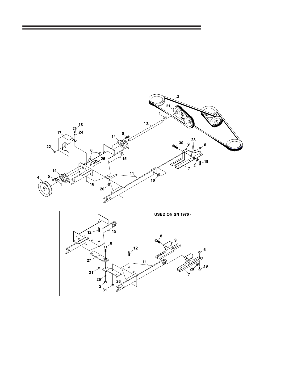
HITCH & DRIVE PARTS
MOWER
ITEM PART NO. DESCRIPTION QTY
7-1 64164-11 KEY-3/16X3/16X1-1/4 SQ 2
7-2 64229-05 LOCKNUT, 1/2-13 NYLON 3
64141-13 NUT WLF 1/2-13 1
7-3 81-A128 BELT-48" 1
81-A158 BELT-60" 1
81-A180 BELT-72" 1
7-4 83-BK5012 PULLEY-5" 3/4" BORE 1
7-5 64139-24 BLT-WLF 3/8-16 X 1 4
7-6 64141-4 NUT-WLF 3/8-16 16
7-7 64-660.7 ANCHOR-LFT ARM RT 2
(USED ON 48" SN 1001 - 1493)
64-934.7 ANCHOR-LFT ARM RT 2
(USED ON 48" SN 1494 - )
64-646.7 ANCHOR-LFT ARM RT 2
(USED ON 60" SN 1001 - 4727)
64-936.7 ANCHOR-LFT ARM RT 2
(USED ON 60" SN 4728 - )
64-668.7 ANCHOR-LFT ARM RT 2
(USED ON 72" SN 1001 - 1969)
64-938.7 ANCHOR-LFT ARM RT 2
(USED ON 72" SN 1970 - )
FIGURE 7
ITEM PART NO. DESCRIPTION QTY
7-18 64139-08 BOLT-5/16-18X3/4 WLF 2
47-077 KNOB-SM CLMPNG W/STUD 1
7-19 64139-21 BLT-WLF 3/8-16X3/4 12
7-20 64229-05 LOCKNUT, 1/2-13 NYLON 1
7-21 83-BK4012 PULLEY-4" 3/4" BORE 1
(USED ON 72" ONLY)
83-BK5012 PULLEY-5" 3/4" BORE 1
(USED ON 60" & 72" MODELS ONLY)
7-22 64229-02 LOCKNUT-NYLON 5/16-18 1
7-23 64163-67 WASHER-.516X1X12 2
7-24 99-G06 WASHER-1/4 1
7-25 64123-54 BOLT, 5/16-18X3/4 HEX 1
7-26 64-933.7 LIFT ARM-TOP LINK 1
7-27 64-932.7 LIFT ARM-LOWER LINK 1
7-28 64141-13 NUT WLF 1/2-13 1
7-29 64006-05 LOCKWSHR-1/2 1
7-30 64123-125 BOLT-HEX 1/2-13X2-3/4 1
7-31 64268-03 NUT-FL NYLON LOCK 3/8-16 4
* 81-A040 BELT 1
* 81-B041 BELT 1
7-8 99-K82 BOLT, FLANGE 1/2-13 X 2 1
7-9 64-661.7 ANCHOR-LFT ARM LFT 2
(USED ON 48" SN 1001 - 1493)
64-935.7 ANCHOR-LFT ARM LFT 2
(USED ON 48" SN 1494 - )
64-645.7 ANCHOR-LFT ARM LFT 2
(USED ON 60" SN 1001 - 4727)
64-937.7 ANCHOR-LFT ARM LFT 2
(USED ON 60" SN 4728 - )
64-669.7 ANCHOR-LFT ARM LFT 2
(USED ON 72" SN 1001 - 1969)
64-939.7 ANCHOR-LFT ARM LFT 2
(USED ON 72" SN 1970 - )
7-10 85-SC08 SET COLLAR-1/2" 2
7-11 62-698.7 HITCH ARM-RIGHT 1
62-858.7 HITCH ARM-RIGHT 1
7-12 64139-24 BLT-WLF 3/8-16 X 1 4
7-13 80-237 SHAFT-MOWER DRIVE 1
7-14 55-FB23012 BRG-2-BOLT FLANGE 3/4 2
7-15 62-699.7 HITCH ARM-LEFT 1
62-857.7 HITCH ARM-LEFT 1
7-16 64141-6 NUT, 5/16-18 2
7-17 64-611.7 SHIELD-DRIVE PULLEY 1
* NOT ILLUSTRATED
31
Page 34

SPINDLE PARTS
ROTARY
FIGURE 8
MOWER
32
Page 35

ROTARY
SPINDLE PARTS
MOWER
ITEM PART NO. DESCRIPTION QTY
8-1 87-235 SHAFT-SPINDLE 1
8-2 87-209843 SEAL 2
8-3 87-244643 BEARING CONE 2
8-4 87-244610 BEARING CUP 2
8-5 87-240001-5 CASTING-W/O BRTHR HLE 1
87-240001-6 CASTING-W/BRTHR HLE 1
8-6 87-240101-01 BLADE ADAPTER W/CUP 1
8-7 87-203293 RETAINING RING 2
8-8 87-203815 BOLT-3/8 X 1-1/2 SHCS 4
FIGURE 8
ITEM PART NO. DESCRIPTION QTY
33
Page 36

FLIP-UP DECKS
ROTARY
FIGURE 9
MOWER
34
Page 37

ROTARY
FLIP-UP DECKS
MOWER
ITEM PART NO. DESCRIPTION QTY
9-1 REF MAIN DECK WELDMENT 1
9-2 40-329.7 IDLER ARM-(48" & 60") 1
40-330.7 IDLER ARM-(72") 1
9-3 64141-2 NUT-WLF 1/4-20 10
9-4 6107645 CHAIN, IDLER ARM STOP 1
9-5 64123-80 BLT-HEX 1/4-20X1-1/4 1
9-6 41-092 SPRING-(60") 1
41-052 SPRING-(48") 1
41-051 SPRING-(72") 1
9-7 64-966 PIVOT STOP PIN 1
9-8 64025-09 HEX, NUT 1/2-13 2
9-9 64006-05 LOCKWSHR-HELICAL 1/2 2
9-10 F1002 NUT, JAM 1/4-20 1
9-11 83-012 IDLER-"V" 1/2" ID X 4-1/2" OD 2
9-12 90-0814 BOLT-1/2 X 1-3/4 1
9-13 64123-50 BOLT-HEX 3/8-16X1 2
9-14 64-799 WASHER-13/32IDX1-9/32OD 2
9-15 85-B29 BUSHING-.406X.740X.258 1
9-16 83-034 IDLER-"V" 3/8" ID X 5" OD 1
(USED ON 72" ONLY)
FIGURE 9
ITEM PART NO. DESCRIPTION QTY
9-31 64163-67 WASHER-.516X1X12 4
9-32 64123-125 BOLT-HEX 1/2-13X2-3/4 1
9-33 64123-87 BOLT-HEX 3/8-16X1-3/4 1
9-34 64139-21 BLT-WLF 3/8-16X3/4 2
(USED ON 72" SN 2592 - )
9-17 64163-61 WSHR .81X.406X16GA 3
(USED ON 72" ONLY)
9-18 64-967.7 FLIP-UP LATCH 1
9-19 41-013 SPRING-EXT. 0.50 X 1.938 1
9-20 64-965.7 FRONT LIFT ARM STOP 1
9-21 64229-03 LOCKNUT-NYLON 3/8-16 1
9-22 64139-04 BOLT-WLF 1/4-20X3/4 8
9-23 64-968.7 FLIP-UP DECK BRACE-LFT 1
(USED ON 60" & 72" ONLY)
64-970.7 FLIP-UP DECK BRACE-LFT 1
(USED ON 48" ONLY)
9-24 64-969.7 FLIP-UP DECK BRACE-RT 1
(USED ON 60" & 72" ONLY)
64-971.7 FLIP-UP DECK BRACE-RT 1
(USED ON 48" ONLY)
9-25 64168-1 COTTER-HAIRPIN.120X2-3/8 1
9-26 62-858.7 ARM, RIGHT HITCH 1
9-27 64-998.7 HOLD DOWN-RLR FRAME 1
(USED ON 72" SN 2592 - )
9-28 64141-4 NUT-WLF 3/8-16 2
9-29 64-939.7 ANCHOR, LIFT ARM LEFT 2
64-938.7 ANCHOR, LIFT ARM RIGHT 2
9-30 64229-05 LOCKNUT, 1/2-13 1
35
Page 38

Equipment from Jacobsen, a Textron company,
is built to exacting standards ensured by
ISO 9001 and ISO 14001 registration at all our
manufacturing locations.
A worldwide dealer network and factory-trained
technicians backed by Textron Parts Xpress
provide reliable, high-quality product support.
BOB-CAT BROUWER BUNTON CUSHMAN RYAN STEINER
 Loading...