

Page 1

CHIPPER / SHREDDER
Model CS312
Starting Serial No. 1001
CHIPPER / SHREDDER BLOWER
Model CS313
Starting Serial No. 1001
Owner/Operator's Manual
& Illustrated Parts List
CAUTION
Avoid injuries. Read and understand Operator’s manual
before operating tractor or equipment.
It contains instructions for safe operation.
Form # 09-282C
Page 2

CAUTION
• READ AND UNDERSTAND OPERATORS MANUAL
BEFORE OPERATING OR SERVICING.
• OBEY ALL SAFETY INSTRUCTIONS. FAILURE TO DO SO
MAY RESULT IN INJURY TO YOU OR OTHERS.
• BE SURE MACHINE IS IN SAFE OPERATING CONDITION
BEFORE USE.
• INSPECT MACHINE DAILY. REPLACE ALL WORN OR
DAMAGED PARTS.
• KEEP ALL GUARDS AND SHIELDS IN PLACE.
• CHECK OPERATION OF ALL SAFETY INTERLOCK
SWITCHES DAILY.
• DO NOT OVERRIDE INTERLOCK SYSTEM, IT IS FOR YOUR
PROTECTION.
• DO NOT ALLOW MINORS OR THE INEXPERIENCED TO
OPERATE MACHINE.
• KEEP PEOPLE AND PETS A SAFE DISTANCE AWAY FROM
MACHINE USING POWER DRIVEN ATTACHMENTS.
INJURY COULD RESULT FROM FLYING DEBRIS.
Date of Purchase: Month ________________Day____________________Year _______________
Dealer Name _________________________Phone__________________
Serial Number ________________________
Model Number ________________________
ALWAYS GIVE MODEL AND SERIAL NUMBER WHEN ORDERING SERVICE PARTS
STEINER TURF EQUIPMENT, INC.
289 N. Kurzen Rd., P.O. Box 504
Dalton, Ohio 44618
Telephone: (330) 828-0200
FAX: (330) 828-1008
Page 3

TABLE OF CONTENTS
INTRODUCTION SECTION 1 page
Description ..........................................1-1
Specifications .........................................1-2
SAFETY SECTION 2
General Safety.........................................2-1
Safety Operating Instructions .................................2-2
INSTALLATION SECTION 3
Mounting Instructions .....................................3-1
OPERATION SECTION 4
Operating Precautions ....................................4-1
Operating Instructions ....................................4-1
Shredding, Chipping & Stopping Instructions ........................4-2
SERVICE SECTION 5
Service Schedule .......................................5-1
Adjustments ..........................................5-2
Trouble Shooting Chart ....................................5-4
PARTS SECTION 6
Parts List and Illustrations Index ...............................6-1
ASSEMBLY SECTION 7
Assembly Instructions.....................................7-1
WARRANTY ......................................last page
3/96 1 - 0 09-282C
Page 4

INTRODUCTION section 1
Description
The Steiner Chipper/Shredder is designed to grind, shred, and chip a variety of materials into a use
able processed material to enrich, beautify and landscape. Mounted on the front of the Steiner 4-wheel
drive articulated frame tractor enables the chipper/shredder to be used in a variety of locations.
Small materials such as leaves, yard and garden debris (cornstalks, plants, prunings, vines, etc.) can
easily be processed through the shredder inlet. Sticks and branches should be limited to 1-1/2 inches in di
ameter and no longer than 24 inches to avoid excess whipping and wrapping. The processed material can
be placed in a compost pile or spread on the ground as mulch, giving a professionally landscaped look.
The chipper inlet can chip branches up to 4 inches in diameter. Several small branches can be
grouped and fed into the chute together. The chipper can reduce a pile of branches and brush into useful
and attractive decorative landscape chips.
-
-
09-282C 1 - 1 3/96
Page 5

INTRODUCTION section 1
Specification
Overall width ________________35-5/8"
Overall height _______________44-1/2"
Overall length _______________53-1/4"
Chipper Knives _______________4hardened
Shredder Sections _____________72hardened
Rotor Diameter _______________18"
Rotor Width ________________12"
Rotor Speed (maximum) ___________1550 RPM
Shredder Throat Opening __________9-1/2" x 11"
Maximum material size for Shredder ______1-1/2" diameter x 24" long
Maximum material size for Chipper ______4"diameter
Application ________________Steiner 420, 425, 525
Power Units only
Weight __________________430lbs.
Specifications are subject to change without notice.
3/96 1 - 2 09-282C
Page 6
SAFETY section 2
ATTENTION: This symbol
identifies potential health
and safety hazards. It
marks safety precautions.
ATTENTION: Your safety
and the safety of others is
involved.
BE ALERT!
SIGNAL WORD DEFINITIONS
DANGER- Indicates an imminently hazardous situation which, if not avoided, will result in death
or serious injury. This signal word is limited to the most extreme cases.
WARNING- Indicates a potentially hazardous situation which, if not avoided, could result in
death or serious injury.
CAUTION- Indicates a potentially hazardous situation which, if not avoided, may result in minor
or moderate injury and/or property damage. It may also be used to alert against unsafe
practices.
GENERAL SAFETY
1. Read and understand the owner's manual,
before attempting to operate this machine.
4. Do not leave equipment unattended. STOP
the engine and remove the key.
2. Operate all controls from the operator's
seat. NO RIDERS.
3. Keep all shields in place and safety switches
adjusted properly.
OPERATING SAFETY
1. STOP ENGINE to install drive belt.
2. DO NOT attempt to work on unit or any
attachments with the engine running. STOP
ENGINE!
3. Before leaving the tractor seat:
1. Disengage PTO.
2. Set PARKING brake.
3. Stop Engine.
5. Do not allow minors or the inexperienced to
operate this machine.
6. Keep people and pets a safe distance away
from machine using power driven attachments. Injury
could result from flying debris.
CAUTION!
ALWAYS WEAR SAFETY
GLASSES WHEN OPERATING
CHIPPER/SHREDDER.
DANGER!
DO NOT OPERATE WITH
PERSONS IN THE AREA.
CHIPPER/SHREDDER MAY
PROPEL OBJECTS CAUSING
POSSIBLE INJURY OR DEATH.
09-282C 2 - 1 3/96
Page 7

SAFETY section 2
Safety Operating Instructions
1. Wear safety glasses at all times while operating the machine.
BE ALERT!
2. The operator should also wear heavy boots, gloves and other ade
quate clothing to protect himself from branches and other sharp or
harmful objects. Avoid wearing loose-fitting clothing.
3. Keep proper balance and footing at all times. Do not overreach.
4. Keep face and body away from the feed opening. Do not allow
hands, feet, or clothing inside the feeding chamber or discharge chute.
5. Move machine to a clear level area outdoors before starting. Do not
operate machine on a paved, concrete or hard gravel surface. Discharged material may rebound.
6. Emergency stop switch must have cable plugged into outlet on
power unit. Do not operate machine without this emergency stop
switch connected.
7. When feeding shreddable material into the machine, be extremely
careful that pieces of metal, rocks, bottles, cans or other foreign objects
are not fed into the feeding chamber.
-
8. If the machine becomes clogged, disengage PTO, stop engine and
allow machine to come to a complete stop before clearing debris.
9. The chipper/shredder rotor may continue to rotate even with the en
gine stopped. Do not attempt any repairs or adjustments until the entire
machine has come to a complete stop. Never operate this machine
without the discharge screen in place.
3/96 2 - 2 09-282C
-
Page 8
INSTALLATION Section 3
Mounting Instructions
The chipper/shredder should be used only on the Steiner 420, 425 and 525 power units equipped
with the required chipper/shredder electrical outlet. (This electrical outlet is shipped with each chip
per/shredder. See Section 7 for electrical outlet installation.)
NOTE: The PTO drive line is subject to shock loads while using the chipper/shredder. Therefore, the
chipper/shredder is not recommended for use on the Steiner 220 power unit. Damage to the hydrostatic
pump may result.
To mount the Chipper/Shredder do the following steps:
1. Open quick hitch latches. Drive tractor into position, aligning the quick hitch. Be sure that both
•
latches are fully engaged and locked.
2. Stop engine! Do not attempt to install drive belt with engine running.
•
• 3. Release double idler assembly to facilitate easy installation of the B-41 drive belt. Put belt over
drive pulley and engage or adjust double idler assembly. (See Power Unit Operator's Manual for
PTO belt tension adjustment.)
-
• 4. Plug emergency stop cable into chipper/shredder electrical outlet on tractor. Be certain the
Emergency Stop Switch is pulled out for normal operation. Do not operate the Chipper/Shredder
without this cable plugged in.
• 5. Remove clip pin and rotate stand to highest position. Reinsert clip pin.
•
6. A rear weight bar with 4 weights is recommended to provide additional stability in transport.
•
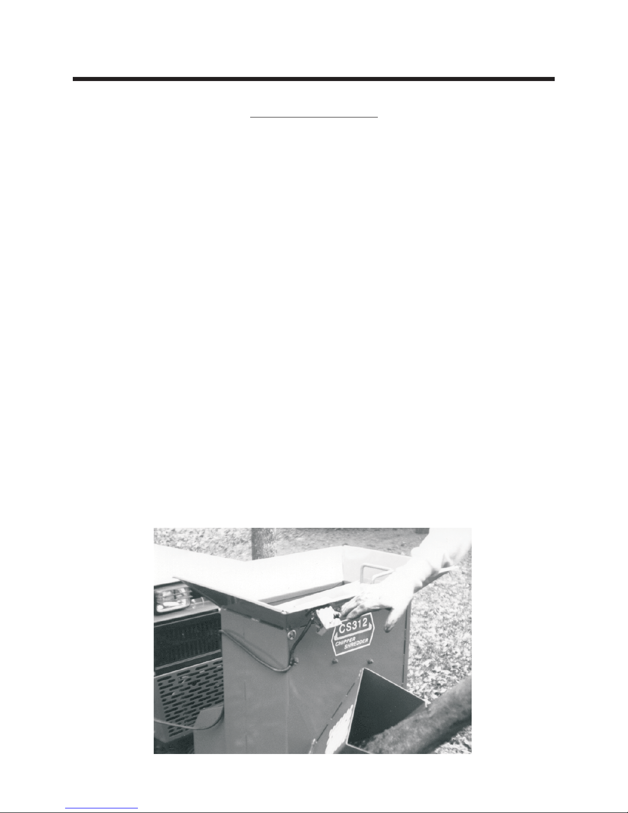
7. Start engine, engage PTO and check operation of Emergency Stop Switch. (See photo below)
09-282C 3 - 1 3/96
Page 9

OPERATION Section 4
Operating Precautions
This chipper/shredder is designed and tested to offer reasonably safe service, however, failure to
operate it in accordance with the following instructions may result in personal injury or death.
Operating Instructions
1. Mount the chipper/shredder according to instructions in Section 3.1.
A rear weight bar with 4 weights is recommended.
2. Wear safety glasses at all times while operating the machine. Also wear heavy boots, gloves, and
adequate clothing to protect from branches and other sharp or harmful objects. Avoid wearing
loose-fitting clothing.
3. Do not operate the chipper/shredder in the vicinity of bystanders. Do not allow minors or the
inexperienced to operate this machine.
4. By using the front lift to transport the machine, move it to a clear level area outdoors. Set the parking brake
on the tractor. Do not operate the chipper/shredder on a paved, concrete or hard gravel surface.
Discharged material may rebound. Lower machine before operating. Do not operate in transport
position.
5. Before starting the machine, make sure the cutting chamber is empty.
6. When feeding shreddable material into the machine, be extremely careful that pieces of metal, rocks,
bottles, cans or other foreign objects are not fed into the feeding chamber.
7. If the cutting mechanism strikes any foreign object, or if the machine should start making an unusual
noise or vibration or become clogged, immediately push the emergency stop switch, stop engine and
allow the machine to come to a complete stop. Take the following steps:
a. Inspect for damage.
b. Clear the debris.
c. Replace or repair any damaged parts.
d. Check for and tighten any loose parts.
8. Keep face and body away from the feed opening. Do not allow hands, feet or clothing inside the feeding
chamber or discharge chute. Do not overreach. Keep proper balance and footing at all times.
3/96 4 - 1 09-282C
Page 10

OPERATION Section 4.2
Shredding Instructions
1. Place material to be shredded (leaves, garden
debris, sticks and branches up to 1-1/2"
diameter and 24" long, etc.) into the hopper.
2. Feed material evenly into the shredder so that the
tractor does not lug down or the shredder
become clogged. If necessary, use the hopper
lid to push the material through the inlet guards.
If the machine becomes plugged it may be
necessary to remove the discharge shield and
screen to clean rotor. Branches or items that
plug or cause the machine to stall should be fed
slowly and carefully.
3. If equipped with a blower, it is recommended to
alternate between dry and green material to
avoid blower plugging.
Chipping Instructions
1. Select limbs that are up to 4 inches in diameter.
Trim side branches that do not fit into the
chipper chute. Small diameter branches can be
held together in a bundle and fed in
simultaneously.
2. Place limb, butt end first, into the chipper chute
until it contacts the chipper blades. The actual
feed rate of the limb into the chipper will depend
on the type of material fed, and sharpness of the
cutting blades. Alternately insert and retract the
limb or insert continuously at a rate that will not
stall the tractor. Rotating the branch as it is fed
will improve cutting action. The chipping knives
will dull with use and require periodic
sharpening. Refer to Service Section 5.2 for
instructions to sharpen chipper knives.
Stopping Instructions
Do not leave machine unattended, or attempt any
inspection or service unless the PTO is disengaged
and tractor engine is shut off. Allow machine to
come to a complete stop.
To stop machine proceed as follows:
1. Move tractor throttle to slow position.
2. Disengage PTO and shut off tractor engine.
3. Allow machine to come to a complete stop.
09-282C 4 - 2 3/96
The rotor is heavy and has inertia that will make the
rotor continue to turn for some time after the tractor
has been shut off. The stopping time can be short
ened by inserting a branch in the chipper chute so
that it contacts the knives and slows the rotor to a
complete stop.
-
Page 11

SERVICE section 5
SERVICE SCHEDULE
Daily:
Check for any signs of loose bolts and tighten as needed.
•
Check chipper knives and sharpen or adjust as needed. (See Page 5-2)
•
25 Hour:
In addition to daily service, remove belt shields and check drive belts for wear or cracking. Replace if
•
worn. (See Section 5.3)
Grease rotor bearings and drive shaft bearings.
•
100 Hour or Annual:
• Remove discharge shield and discharge screen and check rotor. Inspect chipper knives and shredder
sections for wear. Replace worn parts for efficient operation. (See Page 5-2 & 5-3)
Storage:
• Thoroughly clean the machine and store in a dry place to prevent rusting of rotor parts.
3/96 5 - 1 09-282C
Page 12

SERVICE section 5
MAINTENANCE AND ADJUSTMENTS
ADJUSTING KNIFE CLEARANCE
Before inspecting or servicing any part of the
machine, disengage PTO and make sure all
moving parts have come to a complete stop.
The chipping knives and shredding sections
are sharp! Use care when working on machine
to avoid injury.
SHARPENING CHIPPER KNIVES
It is recommended that the chipper knives are
sharpened every 5 to 15 hours of chipper
operation, depending on the type of wood fed
into the chipper.
To remove the chipper knives for sharpening, first
remove the discharge shield and the discharge
screen. Remove the two 5/16 inch retaining bolts
and pull the screen outward. Remove the knife
access cover. Rotate the rotor so that the bolts
holding the chipper knife are accessible. Remove
the two bolts holding the knife and the knife itself.
Repeat for all 4 knives.
Grind the knife at 45 degrees.(See Figure A) The
knives can be ground on a bench grinder or by a
professional. Be careful when grinding so that the
knife material does not get too hot and change
color, this will remove the knife's special heat
treated properties. Use short grinding times and
cool with water. Try to remove an equal amount
off each knife to maintain balance. Replace the
chipper knives and tighten bolts to 20 foot
pounds. Replace the discharge screen.
The chipper knife should clear the chipping block
by 1/8 inch.(See Figure B) To adjust the knife
clearance, proceed as follows:
A. Remove the belt shield, discharge shield, and
the discharge screen. Remove the shaft cover
on the front side.
B. Loosen the two set screws holding the set collar
at the front rotor bearing. Loosen the set
screws holding the lock collars on the front and
rear rotor bearings.
C. Use a punch and hammer and tap the collars in
a direction opposite shaft rotation so they can
rotate freely.
D. Using a soft face mallet, tap the end of the rotor
shaft to obtain 1/8" clearance between the
chipper knife and the chipper block.(See
Figure B) Knife clearance can be checked at
the chipper inlet chute. Rotate the rotor and
check the clearance on all chipper knives.
E. When the clearance has been set, tighten the
eccentric lock collars on the bearings by
rotating them in the direction of shaft rotation.
Using a punch and hammer, “set” them with a
positive hammer tap. Tighten the lock collar set
screws. Slide the set collar against the front
bearing lock collar and tighten the two set
screws.
F. Check the double drive belts for proper
alignment. It may be necessary to move the
pulley on the rotor shaft an equal distance the
rotor was moved.
G. Make sure all set screws are tight and replace
discharge screen and all shields which were
removed.
Figure A
09-282C 5 - 2 3/96
Figure B
Page 13

SERVICE section 5
MAINTENANCE AND ADJUSTMENTS
Before inspecting or servicing any part of the
machine, disengage PTO and make sure all
moving parts have come to a complete stop.
The chipping knives and shredding sections are
sharp! Use care when working on machine to
avoid injury.
SHREDDER SECTIONS
E. See also Cleaning Plugged Blower.
The serrated self sharpening shredder sections
are designed to offer long life and can be
reversed if they become dull. To remove or
replace the sections, proceed as follows:
A. Remove discharge shield, discharge screen and
knife access cover.
B. Work with one section shaft at a time. Remove
the #10-24 bolt from the section shaft. The shaft
can be removed through the access hole.
C. Remove sections and section spacers. Be
careful to keep track of the order the spacers
were installed on the shafts so they can be
returned to the original locations. If the spacers
are not installed properly, the rotor will be out of
balance and also will not have proper
shredding action.
D. Reverse or replace sections and reassemble
into the rotor. Reinstall #10-24 bolt and locknut
through spacer and torque to 36 inch pounds.
E. Complete service of all 6 shafts and replace the
knife access cover, discharge screen and
discharge shield.
BELT REPLACEMENT
Check the condition of the double drive belts
every 30 hours of operation or annually,
whichever occurs first. Only replace belts in sets.
To replace belts proceed as follows:
A. Disengage PTO and stop engine.
B. Remove belt shields.
C. Remove belt idler spring and remove belts from
pulleys.
D. Remove 4 bolts attaching hitch assembly to
main frame and completely remove belts.
E. Place new belts around the hitch frame and
attach the hitch assembly to the main frame.
F. Position belts on the pulleys and attach the idler
arm spring.
G. Check the attachment drive belt and replace if
needed. Replace belt shields.
CLEANING PLUGGED ROTOR
If too large of material or too much material is fed
into the chipper/shredder, it may become
plugged. To clear plugged rotor, proceed as
follows:
A. Disengage PTO and stop engine.
B. Remove discharge shield and discharge screen.
C. Clean debris out of the shredding rotor. Turn the
rotor by hand to be sure it is free to rotate.
D. Replace discharge screen and discharge shield.
3/96 5 - 3 09-282C
CLEANING PLUGGED BLOWER
If too much green material is fed into the
chipper/shredder the blower may become
plugged. To clear the blower, proceed as follows:
A. Disengage PTO and stop engine.
B. Remove blower drive belt guard, and remove
drive belt.
C. Remove the Blower discharge tube.
D. Tilt the blower away from the main frame and
clean debris out of blower housing.
Page 14

SERVICE section 5
TROUBLE SHOOTING
SYMPTOM: Rotor stops or engine stalls.
Possible Cause Remedy
1. Obstructed discharge.
2. Plugged rotor.
SYMPTOM: Hard to feed chipper or excessive power needed to chip.
Possible Cause Remedy
1. Obstructed discharge.
2. Dull chipper knives.
3. Improper knife clearance.
SYMPTOM: Shredder requires excessive power or stalls
Possible Cause Remedy
1. Obstructed discharge.
2. Plugged rotor.
3. Green material will not discharge.
SYMPTOM: Drive belts squealing or smoking
Possible Cause Remedy
1. Use branch or similar object to clear discharge.
2. Clear rotor. (See Section 5.3)
1. Use branch or similar object to clear discharge.
2. Sharpen knives. (See Section 5.2)
3. Adjust knife clearance. (See Section 5.2)
1. Use branch or similar object to clear discharge.
2. Clear rotor, feed material into hopper more
slowly. (See Section 5.3)
3. Alternately feed dry material, or allow material to
dry before shredding.
1. Plugged rotor.
2. Loose or worn belts.
SYMPTOM: PTO will not engage or engine stops when PTO is engaged
Possible Cause Remedy
1. Emergency stop switch is “IN”. 1. Pull emergency stop switch “OUT” for normal
09-282C 5 - 4 3/96
1. Clear rotor. (See Section 5.3)
2. Adjust belt tension or replace belts if needed.
operation.
Page 15

PARTS section 6
PARTS INDEX
GROUP FIGURE PAGE
Hitch & Drive Parts ............Figure 1 ......................6-2
Frame Parts ...............Figure 2 ......................6-4
Emergency Stop Switch Parts ......Figure 3 ......................6-6
Chipper/Shredder Blower Parts .....Figure 4 ......................6-8
ALWAYS GIVE MODEL AND SERIAL NUMBER WHEN ORDERING SERVICE PARTS.
Model CS312 begins with Serial Number 1001
Model CS313 begins with Serial Number 1001
3/96 6 - 1 09-282C
Page 16

PARTS section 6
Hitch and Drive Parts
Figure 1
rev 8/98 6 - 2 09-282C
Page 17

PARTS section 6
Parts List for Figure 1
Ref Part no. Description Quantity
1 83-2TB124 Pulley, 2-groove 12-3/4 diameter 1
2 81-B054 Belt, B54 2
3 83-Q124 Bushing, Q1 x 1-1/2 1
4 85-K0612 Key, 3/8 x 1-1/2 1
5 99-K26 Flange Bolt, 1/4 x 3/4 5
6 00-093 Decal, Warning Read Owner's Manual 1
7 60-576 Shield, Belt 1
8 92-08 Nut, 1/2 5
9 96-08 Lock Washer, 1/2 5
10 90-0810 Bolt, 1/2 x 1-1/4 4
11 02-PP0524 Presto Pin, 5/32 x 2-15/16 1
12 99-F36 Bolt, Special 1/2 x 1-1/2 1
13 62-757 Hitch Frame 1
14 99-E20 Flange Nut, 1/4 1
15 90-0822 Bolt, 1/2 X 2-3/4 1
16 80-244 Drive Shaft 1
17 55-FB23016 Flange Bearing, 2 Bolt, 1" 2
18 90-0610 Bolt, 3/8 X 1-1/4 4
19 83-BK52H Pulley 1
20 83-H16 Bushing, 1" 2
21 85-K0410 Key, 1/4 X 1-1/4 2
22 62-758 Support Stand 1
23 99-E12 Flange Nut, 5/16 5
24 99-K19 Bolt, Flange 5/16 x 3/4 1
25 83-028 Flat Idler 1
26 99-K02 Bolt, Flange 5/16 X 1 4
27 96-06 Lock Washer, 3/8 6
28 92-06 Nut, 3/8 7
29 83-2BK50H Pulley 1
30 60-575 Shield, Drive Pulley 1
31 00-025 Decal, Warning Keep Hands Away 1
32 41-010 Spring, 5" 1
33 90-0612 Bolt, 3/8 X 1-1/2 1
34 99-A06 Locknut, 3/8 1
35 95-08 Flat Washer, 1/2 SAE 2
36 99-A08 Locknut, 1/2 Stover 1
37 40-300 Idler Arm 1
38 95-06 Flat Washer, 3/8 SAE 2 or A/R
39 90-0622 Bolt, 3/8 x 2-3/4 1
* 81-B041 Drive Belt, B41 1
* 30-004B Terminal, Female Spd. 1
* Not Illustrated
09-282C 6 - 3 rev 5/00
Page 18
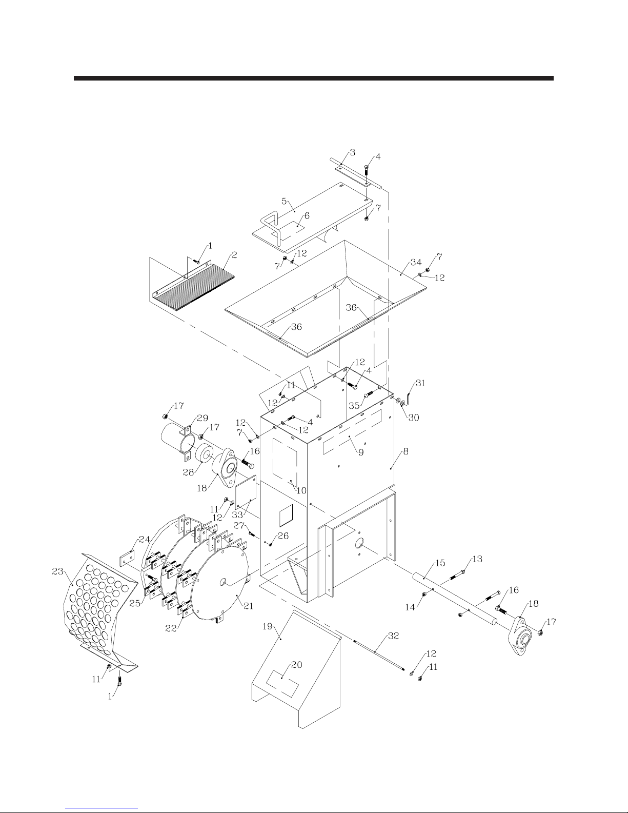
PARTS section 6
Frame Parts
Figure 2
rev 5/00 6 - 4 09-282C
Page 19

PARTS section 6
Parts List for Figure 2
Ref Part no. Description Quantity
1 90-0506 Bolt, 5/16 X 3/4 8
2 87-CS16068 Brush, Inlet 2
3 64-732 Hinge Rod, Lid 1
4 99-K19 Flange Bolt, 5/16 x 3/4 12
5 60-578 Hopper Lid 1
6 00-093 Decal, Warning Read Owner's Manual 1
7 99-E12 Flange Nut, 5/16 13
8 62-756 Main Frame Housing (Serial No. 1001 - 1035) 1
62-787 Main Frame Housing (Serial No 1036 - ) 1
9 00-004 Decal, Steiner 1
10 00-156 Decal, Caution and Operating Instructions 1
11 87-CS15356 Locknut, 5/16 NYL 12
12 95-05 Flat Washer, 5/16 SAE 29
13 90-0620 Bolt, 3/8 x 2-1/2 2
14 87-CS15388 Locknut, 3/8 NYL 2
15 87-CS70379 Shaft, Rotor 1
16 90-0816 Bolt, 1/2 X 2 4
17 99-AC08 Locknut, Center 1/2 6
18 87-CS16004 Bearing, 2 BLT FLG 1-1/2" 2
19 60-577 Discharge Chute 1
20 00-153 Decal, Discharge Shield 1
21 87-CS70583 Rotor, Assembly (incl. Ref 22 and 24)(Ser. No. 1001 - 1159) 1
87-CS70969 Rotor, Assembly (incl. Ref 22 and 24)(Ser. No. 1160 - ) 1
87-CS70584 Weldment, Rotor (Ser. No. 1001 - 1159) 1
87-CS72689 Weldment, Rotor (Ser. No. 1160 - ) 1
22 87-CS70972 Shredder Kit, Consists of: 1
87-CS70856 Shredder Knife 36
87-CS70381 Shaft, Section Knife 6
87-CS70367 Spacer, 0.75 x 0.59 10
87-CS70368 Spacer, 0.75 x 0.59 w/hole 2
87-CS70369 Spacer, 0.75 x 1.18 8
87-CS70370 Spacer, 0.75 x 1.18 w/hole 4
87-CS70371 Spacer, 0.75 x 1.47 18
87-CS17898 Cap Screw, Socket Head 10-24x1-1/4 6
87-CS15397 Locknut, 10-24 NYL 6
23 87-CS70332 Coarse Screen 1
24 87-CS70453 Knife Kit (set of 4, with Ref. 25)(Ser. No. 1001 - 1159) 1
87-CS72493 Knife Kit (set of 4, with Ref. 25)(Ser. No. 1160 - ) 1
25 90-0508 Bolt, 5/16 X 1 8
26 99-E20 Flange Nut, 1/4 1
27 99-K26 Flange Bolt, 1/4 x 3/4 1
28 86-049 Set Collar, Special 1
29 87-CS70426 End Cap 1
30 95-08 Flat Washer, 1/2 SAE 4
31 02-CP0408 Cotter Pin, 1/8 x 1 2
32 87-CS70397 Rod, Discharge Shield 1
33 87-CS70396 Cover, Knife Access 1
34 60-596 Hopper (Serial No. 1036 - ) 1
35 97-0506 Carriage Bolt, 5/16 x 3/4 1
36 00-152 Decal, Danger Keep Hands..Inlet
* 00-155 Decal, Model CS312 1
* Not Illustrated
(2 shown&2onchipper chute) 4
09-282C 6 - 5 rev 5/00
Page 20

PARTS section 6
Emergency Stop Switch Parts
Figure 3
rev 8/98 6 - 6 09-282C
Page 21

PARTS section 6
Parts List for Figure 3
Ref Part no. Description Quantity
1 31-020A Knob, Black for 31-020 1
2 99-K26 Flange Bolt, 1/4 x 3/4 2
3 99-E20 Flange Nut, 1/4 6
4 64-731 Safety Switch Bracket 1
5 00-154 Decal, Emergency Stop 1
6 31-020 Switch, Push-Pull 1
7 11-016 Wire Clip, 13/32 2
8 30-173 Cable, 3-wire Switch to Plug - 60" 1
9 30-163 Connector Plug, 4 pole 1
10 30-164 Connector Socket, 4 pole 1
11 64-733 Mounting Bracket, Electrical Socket 1
12 30-174 Wiring Harness, All Model 420 & 425 w/o electric clutch 1
30-175 Wiring Harness, Model 425 with electric clutch 1
30-187 Wiring Harness, Model 525 with electric clutch 1
13 30-112 Connector, for 35-067 1
14 35-067 Relay 1
15 99-K31 Flange Bolt, 1/4 x 1/2 4
09-282C 6 - 7 rev 8/98
Page 22

PARTS section 6
MODEL CS313
Chipper/Shredder Blower Parts
Figure 4
rev 5/00 6 - 8 09-282C
Page 23

PARTS section 6
MODEL CS313
Parts List for Figure 4
Ref Part no. Description Quantity
1 87-CS70521 Hinge Pin, 5/16 x 14" 1
2 95-05 Flat Washer, 5/16 SAE 9
3 87-CS15356 Locknut, 5/16 NYL 11
4 87-CS70471 Impeller 1
5 87-CS70604 Shaft, Blower 1
6 90-0516 Bolt, 5/16 x 2 1
7 87-CS70586 Housing, Blower 1
8 87-CS17960 Clamp, 4-1/4" ID 1
9 87-CS70249 Blower Tube 1
10 97-0506 Carriage Bolt, 5/16 x 3/4 2
11 87-CS70253 Spout, Blower Tube 1
12 87-CS15321 Knob 1
13 90-0508 Bolt, 5/16 X 1 1
14 90-0506 Bolt, 5/16 X 3/4 10
15 00-002 Decal, Steiner Small 1
16 00-138 Decal, Danger-Rotating Blades 1
17 87-CS15402 Speed Nut, 5/16 4
18 87-CS17692 Spring, Extension 3/4" OD 1
19 87-CS69126 Spacer, Idler Pivot 1
20 87-CS15060 Carriage Bolt, 3/8 x 2 1
21 87-CS70475 Idler Plate, Blower 1
22 87-CS17740 Pulley, Idler 3-1/2" 1
23 87-CS15388 Locknut, 3/8 NYL 1
24 87-CS17831 Bearing, 1" Flushmount, 3 Bolt 2
25 87-CS15391 Key, Square 1/4 x 2" 1
26 87-CS17958 Pulley, Cast 1" Bore, 4" OD 1
27 87-CS70602 Belt Guard 1
28 87-CS16086 V-Belt, BX49 1
29 87-CS16016 Bushing, 1-1/2 1
30 87-CS16499
31 87-CS15441 Key, 3/8 x 1/4 x 2" 1
32 99-AC08 Locknut, 1/2 1
33 87-CS70496 Bracket, Belt Guard 1
34 00-093 Decal, Warning Read Owner’s Manual 1
Pulley, 3.6 x 1B-SH
1
09-282C 6 - 9 rev 8/02
Page 24

ASSEMBLY section 7
INSTALLATION INSTRUCTIONS FOR EMERGENCY STOP SWITCH OUTLET ON MODEL 420
Model 420 (Serial No. 1001 -- 2999)
1. Disconnect the battery ground cable.
2. On model 420 with Onan engine, mount the
electrical outlet on the left side of the black
upper grille panel with two 1/4 x 3/4 flange bolts
and nuts. Choose a location using the existing
slots in the panel. On models with Kubota
engines, the outlets are mounted on the right
side.
3. Connect the new harness (Part No. 30--174) to
the electrical outlet following the wiring diagram
on Page 3. Connect the brown wire to the “W”
terminal, the green wire to the “G” terminal and
the black wire to the “BK” terminal.
4. Locate the black module under the dash and
find the brown wire in the bulk connector.
Remove the bulk connector and carefully
release the brown wire from the connector with
a small blade pocket screwdriver. Place the
single black plastic connector on this brown
wire and connect to the new harness matching
connector. This is the seat switch wire.
5. Locate the brown jumper wire on the wiring
harness. (connected with a blue 3M connector)
Plug the end of the brown jumper wire into the
module bulk connector where the brown wire
was removed in step 3. Connect the bulk
connector to the module.
6. Route the white wire to the ignition switch. Find
the accessory terminal (white wire). Remove
the wire and place the double male spade
adapter on the switch. Replace the wire and
connect the white wire to the other terminal of
the double spade. NOTE: On Kubota tractors,
cut the spade terminal off the white wire, crimp
the enclosed ring terminal to the white wire and
attach it to the accessory terminal of the ignition
switch.
7. Check the wiring diagram and snap the brown
seat switch wire in the relay bulk connector
aligned with 87A on the relay. The brown wire
from the module aligns with 30. The black wire
aligns with 85 and the white wire with 86. Snap
these in place and push the connector on the
relay.
8. Mount the relay using one of the module
mounting screws.
9. Connect the green wire ring terminal to a
suitable ground. Tie all wires to keep them from
contact with moving parts or exhaust system.
10. Reconnect the battery cable, plug in the
chipper/shredder cable and test the
emergency stop switch for proper operation.
Pull the switch out for normal operation. Start
engine and engage the PTO. Push in for
emergency stop.
Model 420 (Serial No. 3000 -- )
1. Disconnect the battery ground cable.
2. On model 420 with Onan engine, mount the
electrical outlet on the left side of the black
upper grille panel with two 1/4 x 3/4 flange bolts
and nuts. Choose a location using the existing
slots in the panel. On models with Kubota
engines, the outlets are mounted on the right
side.
3. Connect the new harness (Part No. 30--174) to
the electrical outlet following the wiring diagram
on Page 3. Connect the brown wire to the “W”
terminal, the green wire to the “G” terminal and
the black wire to the “BK” terminal.
4. Locate the safety interlock relay under the dash
and find the brown wire in the bulk connector.
Remove the bulk connector and carefully
release the brown wire from the connector with
a small blade pocket screwdriver. Place the
single black plastic connector on this brown
wire and connect to the new harness matching
connector. This is the seat switch wire.
5. Locate the brown jumper wire on the wiring
harness. (connected with a blue 3M connector)
Plug the end of the brown jumper wire into the
safety relay bulk connector where the brown
wire was removed in step 3. Connect the bulk
connector to the safety relay.
6. Route the white wire to the ignition switch. Find
the accessory terminal (white wire). Remove
the wire and place the double male spade
adapter on the switch. Replace the wire and
connect the white wire to the other terminal of
the double spade. NOTE: On Kubota tractors,
cut the spade terminal off the white wire, crimp
the enclosed ring terminal to the white wire and
attach it to the accessory terminal of the ignition
switch.
7. Check the wiring diagram and snap the brown
seat switch wire in the new relay bulk connector
aligned with 87A on the new relay. The brown
wire from the safety relay aligns with 30. The
black wire aligns with 85 and the white wire with
86. Snap these in place and push the connector
on the relay.
8. Mount the new relay by drilling a hole in the
battery tray of the Onan power units. On Kubota
units, drill a hole at a suitable location on the
side of the dash panel.
9. Connect the green wire ring terminal to a
suitable ground. Tie all wires to keep them from
contact with moving parts or exhaust system.
10. Reconnect the battery cable, plug in the
chipper/shredder cable and test the
emergency stop switch for proper operation.
Pull the switch out for normal operation. Start
engine and engage the PTO. Push in for
emergency stop.
09-282C 7 - 1 rev 8/97
Page 25

ASSEMBLY section 7
INSTALLATION INSTRUCTIONS FOR EMERGENCY STOP SWITCH OUTLET ON MODEL 425
Model 425 Tractors without
1. Disconnect the battery ground cable.
2. Mount the Electrical outlet on the right side of
the black upper grille panel with two 1/4 x 3/4
flange bolts and nuts. Choose a location using
the existing slots in the panel.
3. Connect the new harness (Part No. 30--174) to
the electrical outlet following the wiring
diagram on Page 3. Connect the brown wire to
the “W” terminal, the green wire to the “G”
terminal and the black wire to the “BK” terminal.
4. Locate the black module under the dash and
find the brown wire in the bulk connector.
Remove the bulk connector and carefully
release the brown wire from the connector with
a small blade pocket screwdriver. Place the
single black plastic connector on this brown
wire and connect to the new harness matching
connector. This is the seat switch wire.
5. Locate the brown jumper wire on the wiring
harness. (connected with a blue 3M connector)
Plug the end of the brown jumper wire into the
module bulk connector where the brown wire
was removed in step 3. Connect the bulk
connector to the module.
6. Route the white wire to the ignition switch. Find
the accessory terminal (white wire). Remove
the wire and place the double male spade
adapter on the switch. Replace the wire and
connect the white wire to the other terminal of
the double spade. NOTE: On Kubota tractors,
cut the spade terminal off the white wire, crimp
the enclosed ring terminal to the white wire and
attach it to the accessory terminal of the ignition
switch.
7. Check the wiring diagram and snap the brown
seat switch wire in the relay bulk connector
aligned with 87A on the relay. The brown wire
from the module aligns with 30. The black wire
aligns with 85 and the white wire with 86. Snap
these in place and push the connector on the
relay.
8. Mount the relay using one of the module
mounting screws.
9. Connect the green wire ring terminal to a
suitable ground. Tie all wires to keep them from
contact with moving parts or exhaust system.
10. Reconnect the battery cable, plug in the
chipper/shredder cable and test the
emergency stop switch for proper operation.
Pull the switch out for normal operation. Start
engine and engage the PTO. Push in for
emergency stop.
11. Proper operation will stop the engine when the
emergency stop switch is pushed “IN”. To
restart, disengage PTO and pull emergency
knob “OUT”.
electric clutch:
Model 425 Tractors with
1. Disconnect the battery ground cable.
2. Mount the Electrical outlet on the right side of
the black upper grille panel with two 1/4 x 3/4
flange bolts and nuts. Choose a location using
the existing slots in the panel.
3. Connect the new harness (Part No. 30--175) to
the electrical outlet following the wiring
diagram on Page 3. Connect the brown wire to
the “W” terminal, the green wire to the “G”
terminal and the black wire to the “BK”
terminal.
4. Locate the clutch relay behind the grille and find
the brown wire in the bulk connector. Remove
the bulk connector and carefully release the
brown wire from the connector with a small
blade pocket screwdriver. This is the seat
switch wire. Insert the brown jumper wire (the
one connected with a blue 3M connector) from
the new harness in its place and push the bulk
connector on the clutch relay as before.
5. Route the white wire to the ignition switch. Find
the accessory terminal (white wire). Remove
the wire and place the double male spade
adapter on the switch. Replace the wire and
connect the white wire to the other terminal of
the double spade. NOTE: On Kubota tractors,
cut the spade terminal off the white wire, crimp
the enclosed ring terminal to the white wire and
attach it to the accessory terminal of the
ignition switch.
6. Check the wiring diagram and snap the brown
seat switch wire in the relay bulk connector
aligned with 87A on the relay. The brown wire
from the new harness aligns with 30. The black
wire aligns with 85 and the white wire with 86.
Snap these in place and push the connector on
the relay.
7. Mount the relay on the rear side of panel using
the clutch relay mounting screw.
8. Connect the green wire ring terminal to a
suitable ground. Tie all wires to keep them from
contact with moving parts or exhaust system.
9. Reconnect the battery cable, plug in the
chipper/shredder cable and test the
emergency stop switch for proper operation.
Pull the switch out for normal operation. Start
engine and engage the PTO. Push in for
emergency stop.
10. Proper operation will disengage the electric
PTO clutch when the emergency stop switch is
pushed “IN”. Do not use the emergency stop
switch as a PTO operational switch. To restart,
disengage tractor PTO switch, pull emergency
knob “OUT” and engage PTO in the normal
manner.
electric clutch:
rev 8/97 7 - 2 09-282C
Page 26

ASSEMBLY section 7
Typical Emergency Stop Switch Wiring Diagram
Two wiring harnesses are shipped with each Chipper/Shredder to adapt to the following tractors:
Model 420 and 425 Tractors without electric clutch
Part No. Description
30-174 Harness with 44" black and brown wires,...and 20" white wire.
Model 425 Tractors with electric clutch
Part No. Description
30-175 Harness with 33" black and brown wires,...and 57" white wire.
09-282C 7 - 3 rev 8/97
Page 27

ASSEMBLY section 7
INSTALLATION INSTRUCTIONS FOR EMERGENCY STOP SWITCH OUTLET ON MODEL 525
Diagram No. 2 for Model 525 Tractors w/o 2 Second Delay
(before serial no. 1197)
Model 525 Tractors:
1. Disconnect the battery ground cable.
2. Mount the electrical outlet on the left side of the
black upper grille panel with two 1/4 x 3/4
flange bolts and nuts. Choose a location using
the existing slots in the panel.
3. Remove the dash access panel. Starting at the
dash area, route the new harness (the end
without terminals) along the existing wiring
harness through the center pivot area of the
tractor. Continue routing until the wires reach
the electrical outlet.
4. Connect the new harness (Part No. 30--187) to
the electrical outlet following the wiring
diagram on this page. Connect the blue wire to
the “W” terminal, the green wire to the “G”
terminal and the black wire to the “BK”
terminal.
5. Locate the clutch relay and circiut breakersin
the dash area. Near the breakers find the
harness with two blue wires that comes from
the seat switch. Disconnect the bullet
connector on the blue seat switch wire and
connect the female bullet connector of the 5
inch brown wire to the male bullet connector on
the blue seat switch wire. Connect the male
bullet of the new green wire to the female bullet
connector of the blue wire that goes to the front
lift limit switch.
6. Route the blue wire from the new harness to the
PTO switch. Find the PTO switch terminal with
the blue wire attached. Remove the wire and
place the double male spade adapter on the
switch. Replace the wire and connect the new
blue wire to the other terminal of the double
spade.
7. Check the wiring diagram and snap the 5 inch
brown seat switch wire in the relay bulk
connector aligned with 87A on the relay. The
green wire from the new harness aligns with 30.
The black wire aligns with 85 and the 10 inch
black wire with ring terminal with 86. Snap
these in place and push the connector on the
safety relay.
8. Mount the safety relay on the left side of
mounting panel using the clutch relay
mounting screw.
9. Connect the black wire ring terminal to a
suitable ground. Tie all wires to keep them from
contact with moving parts or exhaust system.
10. Reconnect the battery cable, plug in the
chipper/shredder cable and test the
emergency stop switch for proper operation.
Pull the switch out for normal operation. Start
engine and engage the PTO. Push in for
emergency stop.
11. Replace all shields.
12. Proper operation will disengage the electric
PTO clutch when the emergency stop switch is
pushed “IN”. To restart, pull emergency knob
“OUT” and engage PTO in the normal manner.
rev 8/97 7 - 4 09-282C
Page 28

ASSEMBLY section 7
INSTALLATION INSTRUCTIONS FOR CHIPPER/SHREDDER WIRE HARNESS ON MODEL 525
EQUIPPED WITH 2 SECOND DELAY RELAY
Wiring Diagram for Model 525 Tractors w/2 Second Delay
(after serial number 1197)
Model 525 Tractors:
1. Disconnect the battery ground cable.
2. Mount the electrical outlet on the left side of the
black upper grille panel with two
bolts and nuts. Choose a location using the
existing slots in the panel.
3. Remove the dash access panel. Starting at the
dash area, route the new harness (the end
without terminals) along the existing wiring
harness through the center pivot area of the
tractor. Continue routing until the wires reach
the electrical outlet.
4. Connect the new wire harness (Part # 30--301)
to electrical outlet installed in Step 2, following
the wiring diagram on this page. Connect the
black wire to the BK terminal, the blue wire to
the W terminal, the gray wire to the R terminal,
and the green wire to the G terminal.
5. Install the supplied relay to the same bolt that
fastens the top of the 30 amp breaker. Position
the relay so that the relay plug will clear the
other bolts on the electrical mounting plate.
6. Remove the blue wire from the load terminal of
the lift cut--off delay relay and install that wire in
the new relay plug so that it connects with the
#87a terminal of the new relay.
7. Install one of the gray wires from the new
harness (30--301) to the load terminal of the lift
cut--off delay relay. Either gray wire can be
used.
8. Install the other gray wire from the new harness
(30--301) into the new relay plug so that it will
connect with the #30 terminal of the new relay.
x flange
9. Install the supplied black wire (approx. 11” long)
to the new relay plug so that it will connect with
the #85 terminal of the new relay. Install the
eyelet end to the ground bolt on the dash. Also
install the black wire from the new harness to
the ground bolt.
10. Install the green wire from the new harness
(30--301) to the new relay plug so that it
connects with the #86 terminal of the new
relay. Install the relay plug onto the new relay.
11. Locate the light blue wire that goes to the
control terminal of the seat switch delay relay.
Cut this wire 3” to 4” from the delay relay plug
and install the supplied male bullet terminals to
both wire ends. Install both ends into the
supplied 3--way electrical connector, also
install the blue wire from the new harness
(30--301) into the 3--way connector.
12. Change the wiring on the emergency stop
switch following the wiring diagram on this
page. The white wire connects to the #4
terminal, the black wire connects to the #5
terminal, the green wire connects to the #2
terminal, and the gray wire connects to the #3
terminal.
13. Reconnect the battery cable, plug in the
chipper/shredder cable and test the
emergency stop switch for proper operation.
Pull the switch out for normal operation. Start
engine and engage the PTO. Push in for
emergency stop.
14. Replace all shields.
15. Proper operation will disengage the electric
PTO clutch when the emergency stop switch is
pushed “IN”. To restart, pull emergency knob
“OUT” and engage PTO in the normal manner.
09-282C 7 - 5 rev 8/97
Page 29

ASSEMBLY section 7
Assembly Instructions for: MODEL CS313 CHIPPER / SHREDDER BLOWER
Refer to Section 6 Parts
Drawing for Identification of
Parts.
1. Remove hinge pin (Fig. 4, Ref. 1)
and remove discharge chute.
2. Remove the end cap from the
rotor shaft.
3. Hold blower up to the main frame
and secure with the new hinge
pin (Fig, 4, Ref. 1) supplied with
the blower assembly.
Photo 1
4. Install pulley, bushing and key
(Fig. 4, Ref. 29, 30, 31) onto the rotor shaft. Do not
secure to shaft at this time.
5. Install belt onto the inside groove on the rotor shaft
pulley, and onto the blower pulley. Idler should run
on the inside of belt for correct tension. (See Photo
1) Align pulleys to within 1/16". Tighten all pulleys on
shafts.
6. Install belt guard support bracket (Fig. 4, Ref.33)
onto top 1/2" bolt for bearing on main frame and
secure with 1/2" lock nut. (Fig. 4, Ref. 32)
7. Install belt guard (Fig. 4, Ref. 27) with (4) 5/16" x 3/4"
bolts and washers.
8. Install blower spout (Fig. 4, Ref. 11) on the blower
tube with (2) 5/16" x 3/4" carriage bolts, (1) 5/16"
locknut and (1) spout knob. Install blower tube onto
blower assembly and secure with clamp. (See
Photo 2)
Photo 2
rev 11/97 7 - 6 09-282C
Page 30

 Loading...