


EST-61715, Tõrvandi, Tartumaa
DGBS
RUS CN BG LV LT EST HR SLO RO PL SK CZ H TR GR N FIN DK S P E I NL F GB D
D
STEINEL Vertrieb GmbH
Dieselstraße 80-84
33442 Herzebrock-Clarholz
Tel: +49/5245/448-188
Fax: +49/5245/448-197
www.steinel.de
Steinel Austria GmbH
A
Hirschstettner Strasse 19/A/2/2
A-1220 Wien
Tel.: +43/1/2023470
Fax: +43/1/2020189
info@steinel.at
PUAG AG
CH
Oberebenestrasse 51
CH-5620 Bremgarten
Tel.: + 41/56/648 88 88
Fax: +41/56/6 4888 80
info@puag.ch
STEINEL U. K. LTD.
GB
25, Manasty Road · Axis Park
Orton Southgate
GB-Peterborough Cambs PE2 6UP
Tel.: +44/1733/366-700
Fax: +44/1733/366-701
steinel@steinel.co.uk
Socket Tool Company Ltd
IRL
Unit 714 Northwest Business Park
Kilshane Drive · Ballycoolin · Dublin 15
Tel.: 00353 1 8809120
Fax: 00353 1 8612061
info@sockettool.ie
STEINEL FRANCE SAS
F
ACTICENTRE - CRT 2
Rue des Famards - Bât. M - Lot 3
F-59818 Lesquin Cedex
Tél.: +33/3/20 30 34 00
Fax: +33/3/20 30 34 20
info@steinelfrance.com
Van Spijk B.V.
NL
Postbus 2
5688 HP OIRSCHOT
De Scheper 402
5688 HP OIRSCHOT
Tel. +31 499 571810
Fax. +31 499 575795
info@vanspijk.nl
www.vanspijk.nl
VSA Belgium
B
Hagelberg 29
B-2440 Geel
Tel.: +32/14/256050
Fax: +32/14/256059
info@vsabelgium.be
www.vsahandel.be
Minusines S.A.
L
8, rue de Hogenberg
L-1022 Luxembourg
Tél. : (00 352) 49 58 58 1
Fax : (00 352) 49 58 66/67
www.minusines.lu
SAET-94 S.L.
E
C/ Trepadella, n° 10
Pol. Ind. Castellbisbal Sud
E-08755 Castellbisbal (Barcelona)
Tel.: + 34/93/772 28 49
Fax: +34/93/772 01 80
saet94@saet94.com
STEINEL Italia S.r.l.
I
Largo Donegani 2
I-20121 Milano
Tel.: +39/02/96457231
Fax: +39/02/96459295
info@steinel.it
www.steinel.it
Pronodis - Soluções Tecnológicas, Lda.
P
Zona Industrial Vila Verde Sul, Rua D, n.º 11
P-3770-305 Oliveira do Bairro
Tel.: +351 234 484 031
Fax: +351 234 484 033
pronodis@pronodis.pt · www.pronodis.pt
KARL H STRÖM AB
S
Verktygsvägen 4
S-553 02 Jönköping
Tel.: +46/36/31 42 40
Fax: +46/36/31 42 49
www.khs.se
Roliba A/S
DK
Hvidkærvej 52
DK-5250 Odense SV
Tel.: +45 6593 0357
Fax: +45 6593 2757
www.roliba.dk
Oy Hedtec Ab
FI
Lauttasaarentie 50
FI-00200 Helsinki
Tel.: +358/207 638 000
Fax: +358/9/673 813
lighting@hedtec.fi · www.hedtec.fi/valaistus
Vilan AS
N
Olaf Helsetsvei 8
N-0694 Oslo
Tel.: +47/22 7250 00
post@vilan.no
www.vilan.no
PANOS Lingonis + Sons O. E.
GR
Aristofanous 8 Str.
GR-10554 Athens
Tel.: + 30/210/321 20 21
Fax: +30/210/3 2186 30
lygonis@otenet.gr
SAOS Teknoloji Elektrik Sanayi ve
TR
Ticaret Limited Şirketi
Halil Rıfat Paşa mahallesi
Yüzerhavuz Sokak
PERPA Ticaret Merkezi A Blok Kat 5 No.313
Şişli / İSTANBUL
Tel.: +90 212 220 09 20
Fax: +90 212 220 09 21
iletisim@saosteknoji.com
www.saosteknoloji.com.tr
ELNAS s.r.o.
CZ
Oblekovice 394
CZ-671 81 Znojmo
Tel.: +4 20/515/22 01 26
Fax: +4 20/515/24 43 47
info@elnas.cz · www.elnas.cz
"LŁ" Spółka z ograniczoną
PL
odpowiedzialnością sp.k.
Byków, ul. Wrocławska 43
PL-55-095 Mirków
Tel.: +48 71 3980818
Fax: +48 71 3980819
handlowy@langelukaszuk.pl
DINOCOOP Kft
H
Radvány u. 24
H-1118 Budapest
Tel.: +36/1/3193064
Fax: +36/1/3193066
dinocoop@dinocoop.hu
KVARCAS
LT
Neries krantine 32
LT-48463, Kaunas
Tel.: +3 70/37/4080 30
Fax: +3 70/37/4080 31
info@kvarcas.lt
EST
Fortronic AS
Tööstuse tee 10,
Tel.: +3 72/7/4752 08
Fax: +3 72/7/3672 29
info@fortronic.ee · www.fortronic.ee
Elektro-Projekt Plus D.O.O.
SLO
Suha pri predosljah 12
SLO-4000 Kranj
Tel.: +386 42 521 645
GSM: +386 40-856555
info@elektroprojektplus.si · www.log.si
NECO SK, A.S.
SK
Ružová ul. 111
SK-01901 Ilava
Tel.: +421/42/4 45 67 10
Fax: +421/42/4 45 67 11
neco@neco.sk · www.neco.sk
Steinel Distribution SRL
RO
Parc Industrial Metrom
RO-500269 Brasov
Str. Carpatilor nr. 60
Tel.: +40(0)268 53 00 00
Fax: +40(0)268 53 11 11
www.steinel.ro
Daljinsko upravljanje d.o.o.
HR
Bedricha Smetane 10
HR-10000 Zagreb
t/ 00385 1 388 66 77
f/ 00385 1 388 02 47
daljinsko-upravljanje@inet.hr
www.daljinsko-upravljanje.hr
AMBERGS SIA
LV
Brivibas gatve 195-16
LV-1039 Riga
Tel.: 00371 67550740
Fax: 00371 67552850
www.ambergs.lv
ТАШЕВ-ГАЛВИНГ ООД
BG
Бул. Климент Охридски № 68
1756 София, България
Тел.: +359 2 700 45 45 4
Факс: +359 2 439 21 12
info@tashev-galving.com
www.tashev-galving.com
Best - Snab
RUS
ул.1812 года, дом 12
121127 Москва · Россия
Tel: +7 (495) 280-35-53
info@steinel.su · www.steinel.su
STEINEL China
CN
Representative Office
Shanghai Rm. 25 A,
Huadu Mansion No. 838
Zhangyang Road Shanghai 200122
Tel: +86 21 5820 4486
Fax: +86 21 5820 4212
info@steinel.net
www.steinel.cn
Information
XLED PRO Wide
XLED PRO Wide XL
XLED PRO Square
110042790 03/2016_I Technische Änderungen vorbehalten. / Subject to technical modification without notice.
XLED PRO Square XL

3
Wide
126
188
135,2
...
D � � � � � � � � � � � 7
GB � � � � � � � � � 12
S � � � � � � � � � � 17
Textteil beachten!
Follow written instructions!
Följ den skriftliga
montageinstruktionen
Square
Wide
D
E
F
G
H
– 2 –
130
230
126
135,2
188
– 3 –
360°
J K L
– 4 –
– 5 –

D
!
!
7.1
7.2
7.3
XLED PRO Square
XLED PRO Square XL
D
1� Zu diesem Dokument
Bitte sorgfältig lesen und aufbewahren!
– Urheberrechtlich geschützt. Nachdruck, auch
auszugsweise, nur mit unserer Genehmigung.
– Änderungen, die dem technischen Fortschritt
dienen, vorbehalten.
Symbolerklärung
Warnung vor Gefahren!
Verweis auf Textstellen im Dokument�
...
2� Allgemeine Sicherheitshinweise
Vor allen Arbeiten am Gerät die
Spannungszufuhr unterbrechen!
• Bei der Installation dieser Geräte handelt es sich
um eine Arbeit an der Netzspannung; sie muss
daher fachgerecht nach den länderspezifischen
Installationsvorschriften und Anschlussbedingungen durchgeführt werden (D-VDE 0100,
a
-ÖVE/ÖNORM E 8001-1, h-SEV 1000)
• Das Strahlergehäuse erwärmt sich während des
Betriebes. Die Ausrichtung des LED-Kopfes nur
durchführen, wenn dieser abgekühlt ist.
• Die Leuchte ist so zu positionieren, dass längeres in die Leuchte starren in einem geringeren
Abstand als 0,3m nicht zu erwarten ist.
Die Sensor-LED Strahler XLEDPROSquare
und XLEDPROWide sind mit Infrarot-Sensoren
ausgestattet. Die Strahler bieten eine Grundhelligkeitsfunktion über zusätzliche Lichtlinien. Die
Slave-Variante dieses LED Strahlers ist mit einem
bauseitigem Schalter/Taster im Stand-Alone-Betrieb ein- und auszuschalten. Haupt- und Grundlicht lassen sich optional über eine zusätzliche
Datenleitung (D-Line) zwischen Sensor-LEDStrahlern (Master-Master) und Slave-LED-Strahler
(Master-Slave) synchron schalten.
Ausführungen
– XLEDPROSquareXL
– XLEDPROSquare
– XLEDPROWideXL
– XLEDPROWide
Lieferumfang
XLEDPROSquare (Abb� 3�1)
XLEDPROWide (Abb� 3�3)
Produktmaße
XLEDPROSquare (Abb� 3�2)
XLEDPROWide (Abb� 3�4)
Geräteübersicht (Abb� 3�5)
A Strahlerkopf
B Grundlicht LED
C Gehäuse
D Funktionseinstellung
- Grundlicht
- Zeiteinstellung
- Dämmerungseinstellung
E Status LED
F IR Sensor
G Abdeckung Bedienelemente
H Wandhalter
I Steckverbindung
3� XLEDPROSquare / Wide
XLED PRO Wide
7.4
Bestimmungsgemäßer Gebrauch
– Sensor-Strahler mit LEDs als Leuchtmittel.
– Geeignet für Wandmontage im Außenbereich.
– Datenleitung (D-Line, optional) für synchrones
Schalten.
360°
XLED PRO Wide XL
– 6 –
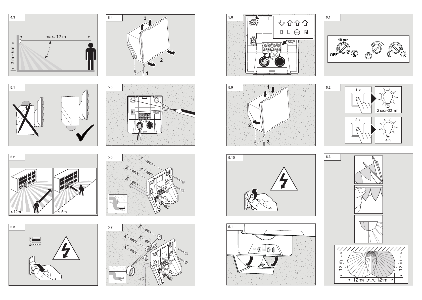
4� Installation
Anschluss Netzzuleitung (Abb� 5�8)
Die Netzzuleitung besteht aus einem 3-adrigen Kabel:
L = Phase (meistens schwarz, braun oder grau)
N = Neutralleiter (meistens blau)
PE = Schutzleiter (grün/gelb)
D = D-Line (Datenleitung) optional
Im Zweifel müssen Sie die Kabel mit einem Spannungsprüfer identifizieren; anschließend wieder
spannungsfrei schalten. Phase (L) und Neutralleiter
(N) werden an der Lüsterklemme angeschlossen.
Anschlussdiagramm (Abb� 4�1 / 4�2)
Reichweitendiagramm (Abb� 4�3)
– 7 –

GB
!
!
1� About this document
Please read carefully and keep in a safe place�
– Under copyright. Reproduction either in whole or
in part only with our consent.
– Subject to change in the interest of technical
progress.
Symbols
Hazard warning!
Reference to other information in
...
the document�
2� General safety precautions
Disconnect the power supply before
attempting any work on the unit�
• Installing these lights involves work on the mains
voltage supply; installation must therefore be
carried out professionally in accordance with the
applicable national wiring regulations and electrical operating conditions (D-VDE 0100, a
-ÖVE/ÖNORM E 8001-1, h-SEV 1000)
• The floodlight enclosure heats up when the light
is on. Only adjust the angle of the LED head
once it has cooled down.
• The light must be positioned so that it is not
expected that anybody can stare into the light
for any prolonged period from a distance of less
than 0.3 m.
3� XLEDPROSquare / Wide
Proper use
– Sensor-switched floodlight with LEDs as light
source.
– Suitable for wall mounting outdoors.
– Data line (D-line, optional) for synchronous
switching.
The XLEDPROSquare and XLEDPROWide
sensor-switched LED floodlights are fitted with
infrared sensors. These floodlights provide a basic
brightness function by means of additional light
lines. In stand-alone mode, the slave version of this
LED floodlight must be switched ON and OFF via a
switch/button to be provided on site. As an option,
main and basic light can be switched ON and OFF
in synchrony via an additional data line (D-line)
between sensor-switched LED floodlights (mastermaster) and slave LED floodlight (master-slave).
Models
– XLEDPROSquareXL
– XLEDPROSquare
– XLEDPROWideXL
– XLEDPROWide
Package contents
XLEDPROSquare (Fig� 3�1)
XLEDPROWide (Fig� 3�3)
Product dimensions
XLEDPROSquare (Fig� 3�2)
XLEDPROWide (Fig� 3�4)
Floodlight components (Fig� 3�5)
A Floodlight head
B Basic light level LED
C Enclosure
D Function setting
- Basic light level
- Time setting
- Twilight setting
E Status LED
F IR sensor
G Cover on controls
H Wall mount
I Plug connection
4� Installation
Connecting the mains power supply lead
(Fig� 5�8)
The mains power supply lead is a 3-core cable:
L = phase conductor
(usually black, brown or grey)
N = neutral conductor (usually blue)
PE = protective-earth conductor (green/yellow)
D = D-line (data line) optional
If you are in any doubt, identify the conductors
using a voltage tester; then disconnect from the
power supply again. Connect phase (L) and neutral
conductor (N) to the terminal block.
Wiring diagram (Fig� 4�1 / 4�2)
Reach diagram (Fig� 4�3)
Note:
A mains switch for switching the light ON and
OFF can be installed in the mains supply lead.
This is required for the manual override function
➜ "6� Functions"
Important:
Mixing up the connections will produce a short
circuit later on in the floodlight or your fuse box. In
this case, you must identify the individual conductors once again and re-connect them.
The light source of this luminaire cannot be
replaced. If the light source needs to be replaced
(e.g. at the end of its service life), the complete
luminaire must be replaced.
5� Mounting
• Check all components for damage.
• Do not use the product if it is damaged.
• Aiming the sensors (Fig� 5�1)
The most reliable way to detect movement is given
by mounting the light to point across the direction
in which people walk and by making sure no
obstacles (e.g. trees, walls etc.) interrupt the line
of sensor vision.
Mounting procedure
• Select appropriate site of installation, giving
consideration to reach and detection of movements (Fig� 5�2)
• Switch OFF power supply (Fig� 5�3)
• Undo retaining screws (Fig� 5�4)
• Detach enclosure from wall mount (Fig� 5�4)
• Mark drill holes (Fig� 5�5)
• Drill holes and insert wall plugs (Fig� 5�6)
– Concealed installation (Fig� 5�6)
– Surface-mounted installation (Fig� 5�7)
• Connect conductors (Fig� 5�8)
• Fit enclosure (C) onto wall mount (G).
Pay attention to plug connection (H) (Fig� 5�9).
• Screw in retaining screws (Fig� 5�9)
• Switch ON power supply (Fig� 5�10)
• Open cover over controls (Fig� 5�11)
• Make settings ➜ "6� Function"
6� Function
Once you have installed the wall mount and connected the floodlight to the power supply, it can
be put into operation. If the floodlight is put into
operation manually at the light switch, it will switch
OFF after 40 s for the calibration phase and is then
activated for sensor mode. It is not necessary to
operate the light switch a second time.
Factory settings
Basic brightness: OFF
Time setting: 5 seconds
Twilight setting: daylight mode
Function (Fig� 6�1)
Basic brightness (Fig� 6�1 / J)
Basic brightness by means of basic light LEDs
provides a low level of illumination. The main light
is only switched on for the time selected when
movement occurs in the detection zone. The light
then switches to the selected level of basic
brightness
– OFF = no basic light
– 10min = basic light for 10min upon expiry of
– "
Time setting / stay-ON time (Fig� 6�1 / K)
The time you want the floodlight to stay on for
(main light) is infinitely adjustable from approx. 5 s
to a maximum of 15min. Any movement detected
before this time elapses will restart the timer.
Note: whenever the light switches OFF, motion
detection is interrupted for approx. 2 s. The light will
only switch ON in response to movement once this
period has elapsed.
Twilight setting / response threshold (Fig� 6�1 / L)
The floodlight's chosen response threshold can be
infinitely varied from approx. 2-1000 lux.
– Control dial set to
– Control dial set to
Manual override function (Fig� 6�2)
If a mains switch is installed in the mains supply
lead, the following functions are provided in
addition to simply switching light ON and OFF:
the time selected
" = basic light all night
= daylight mode (depending
on ambient brightness)
= twilight mode (approx. 2 lux)
GB
– 12 –
– 13 –

Sensor mode: (Fig� 6�2)
– Switch light ON (when light is OFF):
– Switch OFF and ON once. Light stays ON for
the period selected.
– Switch light OFF (when light is ON):
– Switch OFF and ON once. Light goes out or
switches to sensor mode.
Manual override: (Fig� 6�2)
– Activate manual override:
– Turn switch OFF and ON twice. The floodlight is
set to manual override for 4 hours (status LED
ON). Then it returns automatically to sensor
mode (status LED OFF).
– Deactivate manual override:
– Switch OFF and ON once. The floodlight goes
out or switches to sensor mode.
Important:
The switch must be actuated in rapid succession
(in the 0.2 - 1 s sec. range).
Reach adjustment
Depending on mounting height, the detection zone
setting can be optimised to suit requirements.
The film shroud can be used for masking out any
number of lens segments to limit reach as required.
Inadvertent triggering is ruled out or the sensor can
be targeted to watch over danger spots.
– limited at side (Fig� 6�3)
– limiting reach (Fig� 6�4)
Other:
– Floodlight adjustment range (Fig� 6�5 / 6�6)
7� Information
Reference to light-distribution curves (Fig� 7�1-7�4)
8� Accessories (optional)
Remote control RC9 (EAN 4007841007638)
The XLEDPRO provides additional functions by
using the RC9 remote control. The optional RC9
remote control makes it easier to install larger-type
lighting systems as it is then no longer necessary to
set each light before it is installed. Any number of
floodlights can be controlled via remote control.
Remote control functions
1. Brightness setting
2. Daylight mode
3. Night mode
4. Teach mode
5. Time setting
6. Any chosen light ON time
7. Manual override
8. Install mode
9. Reset
Smart remote (optional)
(EAN 4007841009151)
– Control via smartphone or tablet
– Replaces remote control
– Load appropriate app and connect by Bluetooth
9� EC Declaration of Conformity
This product complies with the requirements
defined in the following standards, legislation and
directives:
– Low Voltage Directive 2014/35/EU
– EMC Directive 2014/30/EU
– RoHS Directive 2011/65/EU
– WEEE 2012/19/EU
10� Technical specifications
Sensor-switched LED
floodlights
Dimensions (W x D x H) XLEDPROSquareXL and XLEDPROSquare: 230 x 178 x 130 mm
Voltage supply 220 - 240 V / 50 / 60 Hz
Output XLEDPROSquareXL / WideXL 48 W
Sensor technology PIR (passive Infrared)
Colour temperature 4000 K (neutral white) SDCM 3
Colour rendering index Ra > 80
Luminous flux XLEDPROSquareXL / WideXL 4400lm, 91.7lm/W
Basic light 10min, 30min (by RC9), all night
LED life expectancy 50,000 h (L70B10 to LM80)
Angle of coverage 240°
Detection reach 12m (mounting height 2m to 6m max.)
Adjustment range 0-90° tilting
Area illuminated XLEDPROSquare 362 cm
Time setting 5 s - 15min (control dial)
Twilight setting 2-1000 lux (potentiometer)
Programme setting OFF = no basic light level, 10min, all night (potentiometer)
Manual override (permanent light) 4 h, adjustable ( button, RC9, smart remote)
IP rating IP 54
Protection class I / IK03
Temperature range -20°C to +40°C
11� Warranty
All rights are based on our warranty period. We
guarantee that your STEINEL Professional sensor
product will remain in perfect condition and proper
working order for a period of 5 years. We guarantee that this product is free from material, manufacturing and design flaws. In addition, we guarantee
that all electronic components and cables function
in the proper manner and that all materials used
and their surfaces are without defects.
XLEDPROSquareXL and XLEDPROSquare
XLEDPROWideXL and XLEDPROWide
XLEDPROWideXL and XLEDPROWide: 188 x 265 x 126 mm
XLEDPROSquare / Wide 24.8 W
XLEDPROSquare / Wide 2400lm, 96.8lm/W
360° swivelling
XLEDPROWide 403 cm
5 s - 60min (smart remote)
10 s - 15min (RC9)
2-1000 lux, infinitely variable (smart remote)
2, 10, 30, 50, 100 lux, daylight mode (RC9)
OFF, 10min – 30min, all night (smart remote)
2
2
Making Claims
If you wish to make a claim, please send your
product complete and carriage paid with the original receipt of purchase, which must show the date
of purchase and product designation, either to your
retailer or contact us at STEINEL (UK) Limited,
25 Manasty Road, Axis Park, Orton Southgate,
Peterborough, PE2 6UP, for a returns number.
For this reason, we recommend that you keep
your receipt of purchase in a safe place until the
warranty period expires. STEINEL shall assume
no liability for the costs or risks involved in returning
a product.
GB
– 14 –
For information on making claims under
the terms of the warranty, please go to
www�steinel-professional�de/garantie
– 15 –

If you have a warranty claim or would like to ask
!
!
any question regarding your product, you are welcome to call us at any time on our service hotline
01733 366700.
Further information:
http://www.steinel.de
12� Troubleshooting
Malfunction Cause Remedy
Sensor-switched LED floodlight
without power
Sensor-switched LED floodlight
will not switch ON
Sensor-switched LED floodlight
will not switch OFF
Sensor-switched LED floodlight
keeps switching ON and OFF
Sensor-switched LED floodlight
switches ON when it should not
n Fuse faulty, not switched ON,
break in wiring
n Short circuit
n Twilight setting in night mode
during daytime operation
n Mains power switch OFF
n Fuse faulty
n Detection zone not properly
targeted
n Continuous movement in the
detection zone
n Animals moving in the detec-
tion zone
n Wind moving trees and
bushes in the detection zone
n Cars on the road being
detected
n Sudden change in tempera-
ture caused by weather (wind,
rain, snow) or air discharged
from fans, open windows
n Sensor-switched LED floodlight
swaying (moving), resulting, for
example, from gusts of wind
or heavy precipitation
n Replace fuse, turn ON mains
switch, check lead with voltage
tester
n Check connections
n Adjust setting
n Switch ON
n Fit new fuse, check connection
if necessary
n Readjust
n Check zone and readjust if
necessary or apply shroud
n Fit shrouds to target sensor;
adjust detection zone, or fit
shrouds
n Fit shrouds to target sensor
n Fit shrouds to target sensor
n Change detection zone,
mount in a different place
n Fit sensor-switched LED
floodlight to a firm surface
S
1� Om detta dokument
Läs noga igenom dokumentet och förvara
det väl!
– Upphovsrättsligt skyddat. Eftertryck, även delar
av texten, är bara tillåtit med vårt samtycke.
– Vi förbehåller oss för ändringar som kan göras
pga av den tekniska utvecklingen.
Symbolförklaring
Varning för fara!
Hänvisning till textställen i dokumentet�
...
2� Allmänna säkerhetsanvisningar
Bryt spänningen före alla arbeten på
produkten!
• Vid installeringen av denna apparat handlar
det om arbeten på nätspänningen och därför
måste arbetet genomföras professionellt enligt
respektive länders installationsföreskrifter och anslutningskrav (D-VDE 0100, a -ÖVE/ÖNORM
E 8001-1, h-SEV 1000)
• Strålkastarens kåpa blir het under driften. Rikta
in LED-lampan sedan den svalnat.
• Lampan bör placeras så, att det inte blir möjligt
att se in i lampan under en längre tid på ett
kortare avstånd än 0,3 m.
3� XLEDPROSquare / Wide
Ändamålsenlig användning
– Sensorlampa med LED som ljuskälla.
– Avsedd för väggmontering utomhus.
– Datalinje (styrledning) för sammankoppling av
flera strålkastare.
Sensor-LED-strålkastarna XLEDPROSquare och
XLEDPROWide har infraröda sensorer. Strålkastarna har en grundljusfunktion via extra ljuslinjer.
Denna LED strålkastares slave-variant tänds och
släcks med en på plats existerande brytare/knapp
i Stand-Alone-drift. Huvud- och grundljus kan som
option kopplas samman via en styrledning (D-Line)
mellan sensor-LED strålkastare (master-master)
och slave-LED strålkastare (master-slave).
Utföranden
– XLEDPROSquareXL
– XLEDPROSquare
– XLEDPROWideXL
– XLEDPROWide
Innehåll
XLEDPROSquare (bild 3�1)
XLEDPROWide (bild 3�3)
Produktmått
XLEDPROSquare (bild 3�2)
XLEDPROWide (bild 3�4)
Översikt över delar (bild 3�5)
A Strålkastarens huvud
B Grundljus LED
C Frontlock
D Funktionsinställning
- grundljus
- efterlystid
- skymningsnivå
E Status LED
F IR sensor
G Skydd för funktionsvred
H Väggfäste
I Kontaktanslutning
4� Installation
Kontakt nätanslutning (bild 5�8)
Nätanslutningens matarledning består av en
3-ledarkabel:
L = Fas (oftast svart, brun eller grå)
N = Neutralledare (oftast blå)
PE = Skyddsledare (grön/gul)
D = D-Line (styrledning)
Vid osäkerhet, måste kabeln identifieras med en
spänningskontroll; gör den därefter spänningsfri
igen. Fas (L) och neutralledare (N) ansluts till
kopplingsplinten.
S
Anslutningsdiagram (bild 4�1 / 4�2)
Räckviddsdiagram (bild 4�3)
– 16 –
– 17 –
 Loading...