

Page 1

08/2015 SENSOREN Version "I"
D STEINEL Vertrieb GmbH
Dieselstraße 80-84 · 33442 Herzebrock-Clarholz
Tel: +49/5245/448-188 · Fax: +49/5245/448-197 · www.steinel.de
A Steinel Austria GmbH
Hirschstettner Strasse 19/A/2/2 · A-1220 Wien
Tel.: +43/1/2023470 · Fax: +43/1/2020189 · [email protected]
CH PUAG AG
Oberebenestrasse 51 · CH-5620 Bremgarten
Tel.: +41/56/6488888 · Fax: +41/56/6488880 · [email protected]
GB STEINEL U.K. LTD.
25, Manasty Road · Axis Park · Orton Southgate
GB-Peterborough Cambs PE2 6UP
Tel.: +44/1733/366-700 · Fax: +44/1733/366-701
[email protected]
IRL Socket Tool Company Ltd
Unit 714 Northwest Business Park
Kilshane Drive · Ballycoolin Dublin 15
Tel.: 00353 1 8809120 · Fax: 00353 1 8612061
[email protected]
F STEINEL FRANCE SAS
ACTICENTRE - CRT 2 · Rue des Famards - Bât. M - Lot 3
F-59818 Lesquin Cedex · Tél.: +33/3/20 30 34 00
Fax: +33/3/20 30 34 20 · [email protected]
NL Van Spijk B.V.
Postbus 2 · 5688 HP OIRSCHOT · De Scheper 402
5688 HP OIRSCHOT · Tel. +31 499 571810
Fax. +31 499 575795 · [email protected] · www.vanspijk.nl
B VSA Belgium
Hagelberg 29 · B-2440 Geel
Tel.: +32/14/256050 · Fax: +32/14/256059
[email protected] · www.vsahandel.be
L Minusines S.A.
8, rue de Hogenberg · L-1022 Luxembourg
Tél. : (00 352) 49 58 58 1 · Fax : (00 352) 49 58 66/67
www.minusines.lu
E SAET-94 S.L.
C/ Trepadella, n° 10 · Pol. Ind. Castellbisbal Sud
E-08755 Castellbisbal (Barcelona)
Tel.: +34/93/772 28 49 · Fax: +34/93/772 01 80
[email protected]
I STEINEL Italia S.r.l.
Largo Donegani 2 · I-20121 Milano
Tel.: +39/02/96457231 · Fax: +39/02/96459295
[email protected] · www.steinel.it
P Pronodis - Soluções Tecnológicas, Lda.
Zona Industrial Vila Verde Sul, Rua D, n.º 11
P-3770-305 Oliveira do Bairro
Tel.: +351 234 484 031 · Fax: +351 234 484 033
[email protected] · www.pronodis.pt
S KARL H STRÖM AB
Verktygsvägen 4 · S-55302 Jönköping
Tel.: +46/36/31 42 40 · Fax: +46/36/31 42 49 · www.khs.se
DK Roliba A/S
Hvidkærvej 52 · DK-5250 Odense SV
Tel.: +45 6593 0357 · Fax: +45 6593 2757 · www.roliba.dk
FI Oy Hedtec Ab
Lauttasaarentie 50 · FI-00200 Helsinki
Tel.: +358/207 638 000 · Fax: +358/9/673 813
[email protected] · www.hedtec.fi/valaistus
N Vilan AS
Olaf Helsetsvei 8 · N-0694 Oslo
Tel.: +47/22725000 · [email protected] · www.vilan.no
GR PANOS Lingonis + Sons O. E.
Aristofanous 8 Str. · GR-10554 Athens
Tel.: +30/210/3212021 · Fax: +30/210/3218630
[email protected]
PL "LŁ" Spółka z ograniczoną odpowiedzialnością sp.k.
Byków, ul. Wrocławska 43 · PL-55-095 Mirków
Tel.: +48 71 3980818 · Fax: +48 71 3980819
[email protected]
CZ ELNAS s.r.o.
Oblekovice 394 · CZ-67181 Znojmo · Tel.: +420/515/220126
Fax: +420/515/244347 · [email protected] · www.elnas.cz
TR SAOS Teknoloji Elektrik Sanayi ve Ticaret Limited Şirketi
Halil Rıfat Paşa mahallesi Yüzerhavuz Sokak
PERPA Ticaret Merkezi A Blok Kat 5 No.313 · Şişli / İSTANBUL
Tel.: +90 212 220 09 20 · Fax: +90 212 220 09 21
[email protected] · www.saosteknoloji.com.tr
H DINOCOOP Kft
Radvány u. 24 · H-1118 Budapest
Tel.: +36/1/3193064 · Fax: +36/1/3193066
[email protected]
LT KVARCAS
Neries krantine 32 · LT-48463, Kaunas
Tel.: +370/37/408030 · Fax: +370/37/408031 · [email protected]
EST Fortronic AS
Tööstuse tee 10 · EST-61715, Tõrvandi, Tartumaa
Tel.: +372/7/475208 · Fax: +372/7/367229
[email protected] · www.fortronic.ee
SLO Elektro-Projekt Plus D.O.O.
Suha pri predosljah 12 · SLO-4000 Kranj
Tel.: +386 42 521 645 · GSM: +386 40-856555
[email protected] · www.log.si
SK NECO SK, a.s.
Ružová ul. 111 · SK-01901 Ilava
Tel.: +421/42/4 45 67 10 · Fax: +421/42/4 45 67 11
[email protected] · www.neco.sk
RO Steinel Distribution SRL
Parc Industrial Metrom · RO - 500269 Brasov · Str. Carpatilor nr. 60
Tel.: +40(0)268 53 00 00 · Fax: +40(0)268 53 11 11
www.steinel.ro
HR Daljinsko upravljanje d.o.o.
Bedricha Smetane 10 · HR-10000 Zagreb
t/ 00385 1 388 66 77 · f/ 00385 1 388 02 47
[email protected] · www.daljinsko-upravljanje.hr
LV Ambergs SIA
Brivibas gatve 195-16 · LV-1039 Riga
Tel.: 00371 67550740 · Fax: 00371 67552850 · www.ambergs.lv
BG ТАШЕВ-ГАЛВИНГ ООД
Бул. Климент Охридски № 68 · 1756 София, България
Тел.: +359 2 700 45 45 4 · Факс: +359 2 439 21 12
[email protected] · www.tashev-galving.com
RUS Best - Snab
ул.1812 года, дом 12 · 121127 Москва · Россия
Tel: +7 (495) 280-35-53 · [email protected] · www.steinel.su
CN STEINEL China
Representative Office · Shanghai Rm. 25 A,
Huadu Mansion No. 838
Zhangyang Road Shanghai 200122
Tel: +86 21 5820 4486 · Fax: +86 21 5820 4212
[email protected] · www.steinel.cn
Information
110033669 09/2015_I Technische Änderungen vorbehalten. / Subject to technical modification without notice.
L 400 S
TR GR N FI DK S P E I NL F GB D
H
LV
RUS
BG LT EST HR SLO RO PL SK CZ
中
Page 2

c
min. 5 min.
min. 5 min.
Halogen
normal/
not dimmable
dimmable
(all dimmers)
0 –50 %
0 –100 %
Tipp!
5 sec. –15 min.
10 % –100 %
Soft
Watt-o-matic
Watt-o-matic
d e
/ /
c d e
a
f
g
- 2 - - 3 -
Page 3
GB
Installation Instructions
Dear Customer,
Congratulations on purchasing your new
STEINEL SensorLight and thank you for the
confidence you have shown in us.
You have chosen a high-quality product that
has been manufactured, tested and packed
with the greatest care.
Please familiarise yourself with these instruc-
Safety precautions
n Disconnect the power supply before attempt-
ing any work on the light.
n During installation, the electrical wiring you
are connecting must be dead. Therefore,
switch off the power first and use a voltage
tester to make sure the wiring is off circuit.
a
Principle
The integrated infrared sensor is equipped with
two 120° pyro sensors which detect the invisible heat emitted by moving objects (people,
animals etc.).
The heat detected is converted electronically
into a signal that switches the light ON automatically. Heat is not detected through obstacles, such. as walls or panes of glass. Heat radiation of this type will, therefore, not trigger
tions before attempting to install the SensorLight because prolonged, reliable and troublefree operation will only be ensured if it is fitted
and used properly.
We hope your new STEINEL SensorLight will
bring you lasting pleasure.
n Installing the SensorLight involves work on
the mains voltage supply. This work must
therefore be carried out professionally in accordance with national wiring regulations and
electrical operating conditions
D
(
-VDE 0100, A -ÖVE / ÖNORM E8001-1,
-SEV 1000).
the sensor. The two pyro sensors have an angle
of coverage of 240° with an angle of aperture of
180°.
Important: The most reliable way of detecting
movement is to install the SensorLight with the
sensor aimed across the direction in which a
person would walk and by ensuring that no obstacles (such as trees, walls etc.) obstruct the
line of sensor vision.
Installation/Wall mounting
The site of installation should be at least 50 cm
away from another light because heat radiated
from it may activate the system. To achieve the
specified max. reach of 12 m, the light should
be installed at a height of approx. 2 m.
Undo the screw on the top panel. Remove
screw and pull out wall mount.
Do not detach internal wiring from terminal
block, but gently pull out entire terminal
assembly.
Hold the mounting plate against the wall and
mark where to drill the holes, paying attention
to any wiring already existing in the wall, drill
holes; insert wall plugs. For the motion detector
to trigger a switching operation, the mains
power must be fed to the load by at least a
two-core cable. To do this, pierce the mounting
plate and fit sealing plug.
The mounting plate can be aligned and screwed
in place after feeding the cables through.
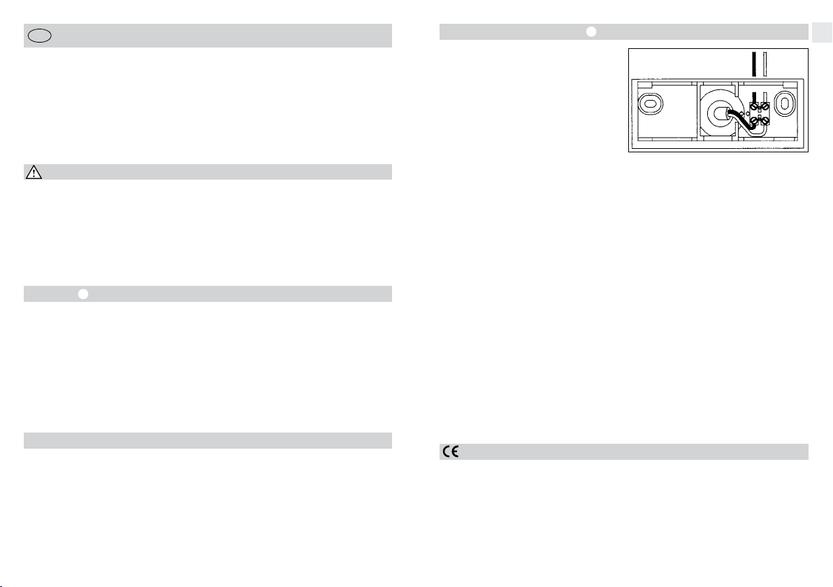
Connecting the mains power supply lead
The mains power supply lead is a 2 to 3-core
cable.
L = phase conductor
(usually black, brown or grey)
N = neutral conductor
(usually blue)
PE = any protective earth conductor
(green/yellow)
If you are in any doubt, identify the conductors
using a voltage tester; then disconnect from the
power supply again.
b
BLACK / BROWN / GREY BLUE
L N
Connect phase conductor (L) and neutral conductor (N) to the terminals to which a cable of
the same colour is already connected. Wrap insulation tape around the end of the protective
earth conductor (PE).
Important: Getting the cable connections
crossed will produce a short circuit in the light
or in your fuse box. In this case, you must
check the identification of all cables and reconnect them.
A mains switch for switching the light ON and
OFF can of course be installed in the mains
lead.
GB
Operation/Maintenance
The SensorLight is suitable for switching light
ON automatically. Weather conditions may affect the way the SensorLight functions. Strong
gusts of wind, snow, rain or hail may cause the
light to come ON when it is not wanted because
the sensor is unable to distinguish sudden
changes of temperature from sources of heat.
The detector lens may be cleaned with a damp
cloth if it gets dirty (do not use cleaning agents).
Declaration of Conformity
This product complies with
- Low-Voltage Directive 2006/95/EC
- EMC Directive 2004/108/EC
- RoHS Directive 2011/65/EC
- WEEE Directive 2012/19/EC
- 10 - - 11 -
Page 4
Technical Specifications
Dimensions (H x W x D) 335.5 x 215 x 249.5 mm
Power supply 220-240 V / 50/60 Hz
Sensor type Passive infrared
Output 60 W max / E27
Angle of coverage 240° with 180° angle of aperture
Capability of masking out
individual segments Yes
Reach 12 m max. (temperature-stabilised)
Sensor system 9 detection levels, 304 switching zones
Response brightness 2-2000 lx
Time setting 5 sec. - 15 min.
Basic lighting level 0 % - 50%
IP rating IP44
Protection class II
Temperature range -20 to +50 °C
Material UV-resistant plastic
Functions
The SensorLight can be put into service after
mounting the sensor unit and connecting the
light to the mains power supply.
Switch-off delay
(time setting) c
(Factory setting: 5 sec.)
Light-level setting
(response threshold) d
(Factory setting:
daylight operation 2000 lux)
c, d, e
5 sec. - 15 min.
2-2000 lux
Light ON duration can be infinitely varied from
5 sec. to 15 min.
Control dial set to – = shortest time
Control dial set to + = longest time (15 min.)
When setting the detection zone, it is recom-
mended to select the shortest time –.
The sensor's response threshold can be
infinitely varied from 2-2000 lux.
Control dial set to
approx. 2000 lux.
Control dial set to
approx. 2 lux.
To adjust the detection zone in daylight,
the control dial must be set to
(daylight operation).
= daylight operation
= twilight operation
Brightness control
(Watt-o-matic) e
(Factory setting:
dimming OFF: 0%)
Light output can be infinitely adjusted up to
50 % of maximum power when set to stay ON
all the time. This means: the light will only
switch from, for instance, 20 watts in permanent lighting mode to maximum output when
movement occurs in the detection zone.
GB
0-50 %
f
Manual override function
If a mains switch is installed in the mains supply
lead, the following functions are provided in
addition to simply switching light ON and OFF:
Sensor operation mode
1) Switch light ON (when light is OFF):
Switch OFF and ON once.
Light stays ON for the period selected.
2) Switch light OFF (when light is ON):
Switch OFF and ON once.
Light goes out or switches to sensor mode.
Manual override
1) Activate manual override:
Turn switch OFF and ON twice. Light is set to
stay ON for 4 hours (red LED lights up behind
lens). Then it returns automatically to sensor
mode (red LED off).
2) Deactivate manual override:
Switch OFF and ON once. Light goes out or
switches to sensor mode.
Important:
The switch should be actuated in rapid succession (in the 0.5-1 sec. range).
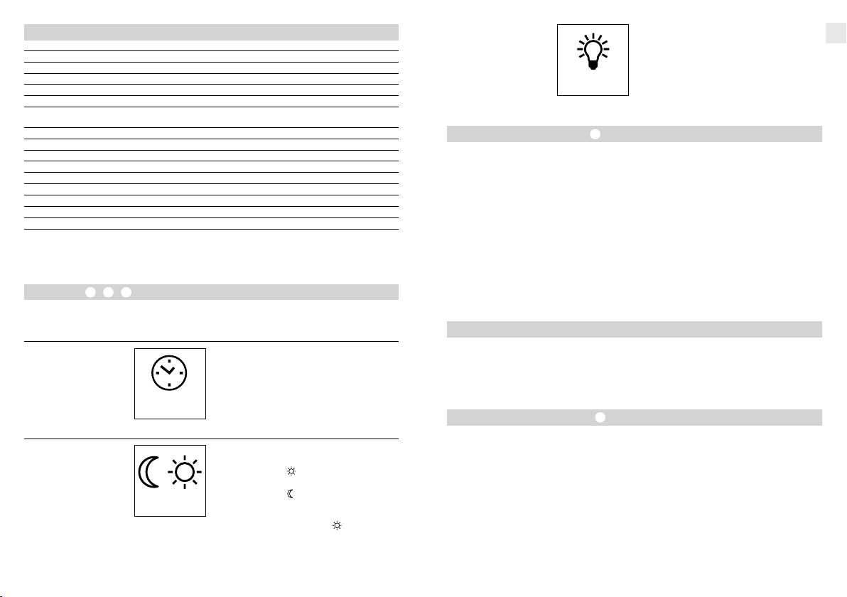
Soft light start
The SensorLight features a soft light start function. This means that when turned ON, the light
is not switched directly to maximum output but
gradually builds up brightness to 100 % within
Reach setting/adjustment
At an assumed installation height of 2 m, the
sensor has a maximum reach of 12 m. The detection zone can be optimised to suit needs.
The shrouds supplied with the sensor can be
used to mask out as many lens segments as
you wish or shorten reach to suit the particular
situation. This prevents the light from being activated unintentionally, e.g. by cars, passers-by
etc., and allows you to target danger spots.
The shrouds can be separated along the pregrooved divisions in the vertical and horizontal
g
the space of a second. Brightness is also gradually reduced when the light is switched OFF.
directions or cut with scissors. After removing
the decorative ring the shrouds can be clipped
on at the top of the sensor lens. The decorative
ring must now be pushed back on to hold the
shrouds firmly in place.
The sensor housing can also be turned through
± 80° for precision targeting.
- 12 - - 13 -
Page 5

Troubleshooting
Malfunction Cause Remedy
SensorLight without power
Sensor light will not switch ON
SensorLight will not switch off
SensorLight switches ON
when it should not
SensorLight reach changed
LED on all the time although
manual override is not selected
n Fuse faulty, not switched
ON, break in wiring
n Short circuit
n Twilight setting in night-
time mode during daytime
operation
n Bulb faulty
n Mains power switch OFF
n Fuse faulty
n Detection zone not proper-
ly targeted
n Internal electrical fuse has
been activated (LED on all
the time)
n Continuous movement in
the detection zone
n Brightness control at 50%
n Wind is moving trees and
bushes in the detection
zone
n Cars in the street are being
detected
n Sudden temperature
changes due to weather
(wind, rain, snow) or air expelled from fans, open windows
n Differing ambient tempera-
tures
n Internal fuse activated n Switch SensorLight OFF
n Replace fuse, turn ON
mains switch, check lead
with voltage tester
n Check connections
n Reset (control dial d)
n Change bulb
n Switch ON
n Fit new fuse, check con-
nection if necessary
n Re-adjust
n Switch SensorLight OFF
and back ON again after
approx 5 sec.
n Check detection zone and
re-adjust if necessary
n Set brightness control to
0% (control e)
n Change zone
n Change zone
n Change detection zone,
change site of installation
n Use shrouds to define
detection zone precisely
and back ON again after
5 sec.
Declaration of Guarantee
All rights are based on our guarantee period.
We guarantee that your STEINEL Professional
sensor product will remain in perfect condition
and proper working order for a period of
5 years. We guarantee that this product is free
from material, manufacturing and design flaws.
In addition, we guarantee that all electronic
components and cables function in the proper
manner and that all materials used and their
surfaces are without defects.
Making Claims
If you wish to make a claim, please send your
product complete and carriage paid with the
original receipt of purchase, which must show
the date of purchase and product designation,
either to your retailer or directly to us at
STEINEL (UK) Limited, 25 Manasty Road,
Axis Park, Orton Southgate, Peterborough,
PE2 6UP. For this reason, we recommend
that you keep your receipt of purchase in a
safe place until the guarantee period expires.
STEINEL shall assume no liability for the costs
or risks involved in returning a product.
For information on making claims under the
terms of the guarantee, please go to
www.steinel-professional.de/garantie
If you have a guarantee claim or would like
to ask any question regarding your product,
you are welcome to call us at any time on our
service hotline 01733 366700.
GB
- 14 - - 15 -
 Loading...