

Page 1
®
STEINDORFF
Stereo
Microscope
NYMCS-320
User
Manual
It is recommended strongly that you study this manual thoroughly before using the microscope.
Retain this manual in an easily accessible place near the work desk for future reference.
Page 2

1
®
Use Notices ………………………………………………………………………………………………….
2
1. Components ……………………………………………………………………………………………
3
2. Assembly ……………………………………………………..………………………………………...
4
2.1. Assembly Diagram ………………………………………………………………………………
4
2.2. Assembly Procedure ……………………………………………………………………………..
5
3. Adjustment and Operation …………………………………………………………………………...
7
3.1. Adjusting Viewing Head ………………………………………………………………………...
7
3.2. Focus Adjustment ………………………………………………………………………………..
8
3.3. Illumination ………………………………………………………………………………………
8
4. Specification ……………………………………………………………………………………………
9
5. Troubleshooting ……………………………………………………………………………………….
9
6. Outfit …………………………………………………………………………………………………...
10
CONTENTS
STEINDORFF
Page 3

2
®
USE NOTICES
STEINDORFF
Safety Precaution
1. Carefully open the box, avoid the accessories, like lens, dropping to ground and being damaged.
2. Check the input voltage, be sure the input voltage which signed on the microscope is consistent with the
power supply voltage, or it will bring a serious damage to the instrument.
3. Do keep the instrument out of direct sunlight, high temperature or humidity, dusty and easy shaking
environment. Make sure the stage is smooth, horizontal and firm enough.
4. To prevent the microscope body from turning over, its pivot angle must be limited to 30°.
5. A microscope is a precision instrument. Handle it with care and avoid subjecting it to sudden or severe
impact.
6. Make sure the instrument is earthed, to avoid lighting strike.
7. Do not disassemble any part of the microscope, especially the electrical parts on the bottom side as this
may result in electric shock.
8. Use the factory supplied power cord, please.
Maintenance and Storage
1. All the lenses have been well checked and adjusted. It is forbidden to disassemble them yourself.
2. The binocular viewing head and focusing unit have a compact and precise frame; please don’t disassemble
them as possibly as you can.
3. Keep the instrument clean, wipe dust regularly, and be attention to avoid contaminating the optical
elements especially.
4. The contaminations on the prism, as fingerprint and oil, could be gently wiped with a piece of soft cloth or
tissue paper, gauze which has been immersed in pure alcohol or ether. (Note that the alcohol and ether are
highly flammable, do keep them away from the fire or potential sources of electrical sparks, and use them
in a drafty room as possible as you can.)
5. Do not attempt to use organic solvents to clean the microscope components other than the glass
components. To clean them, use a lint-free, soft cloth slightly moistened with a diluted neutral detergent.
6. If the microscope is splashed by liquid during using, cut off the power at once, and wipe up the moisture.
7. Do not disassemble any parts of the microscope, which will affect the function or decline the performance
of the microscope.
8. Place the instrument in a cool, dry position. When not using the microscope, keep it covered with a dust
cover.
Page 4
3
®
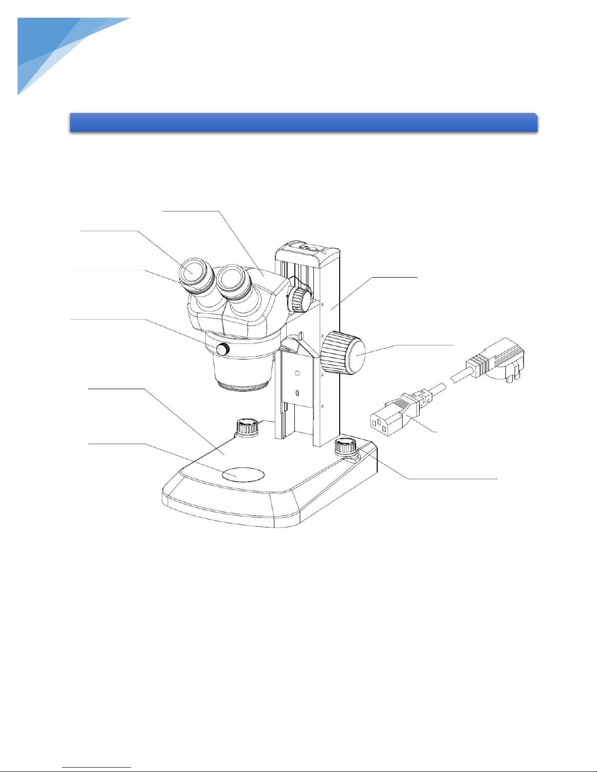
1. COMPONENTS
Binocular head and zoom body
WF10x eyepieces
Diopter ring
Clamping knob
Standard base
Glass stage
Stand
Focusing knob
Power cord
Brightness
STEINDORFF
NYMCS-320 Stereo Microscope
Page 5
4
®
2. ASSEMBLY
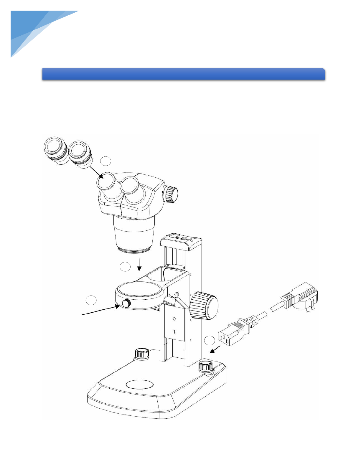
2 1 3
4
WF10x eyepieces
Binocular head and zoom body
Power cord
STEINDORFF
2.1. Assembly Diagram
The diagram below shows how to assemble the various modules. The numbers indicate the order of assembly.
When assembling the microscope, make sure that all parts are free of dust and dirt, and avoid scratching
any parts or touching glass surfaces.
Page 6
5
®
1
2
3
4
5
Note:
Working Environment Requirement:
1. Ambient temperature: 5°C to 40°C. (41°F to 104°F),
Maximum R.H: 85°.
2. High Temperature will result in a mildewing, dew and even
ruinous instrument.
3. Avoid placing the instrument in a dusty environment. When
ending your microscope operation, please cover it with the
dust cover.
4. Lay the microscope in a plan and stable position, please.
Figure 1
Figure 2
Figure 3
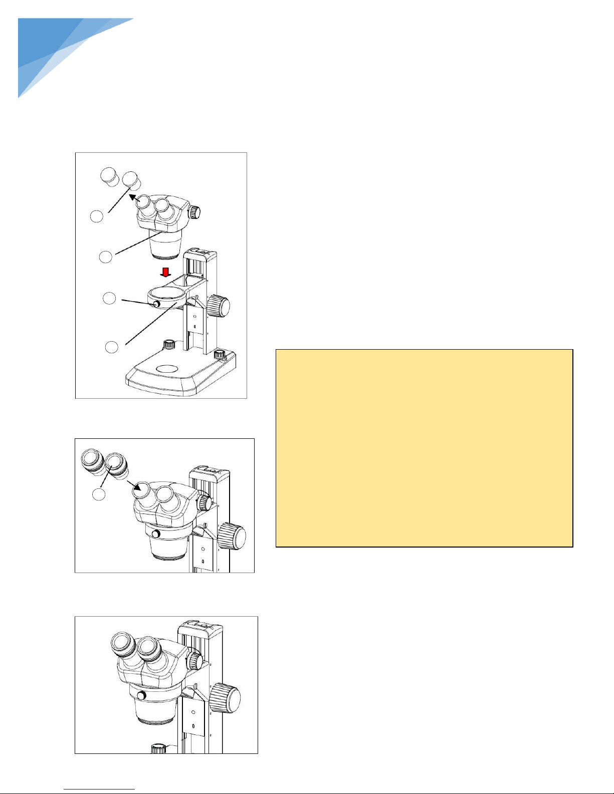
2.2.1. Mounting binocular head (Figure 1)
Loose the clamping bolt ③ on the pillar ④ and insert the
binocular head and zoom body assembly ② into the
bracket of the pillar, then screw down the bolt ③.
2.2.2. Mounting eyepieces (Figure 1, Figure 2, Figure 3)
Remove the eyepiece dust caps ① and gently insert two
adjustable eyepieces ⑤ into the eyepiece sleeves until
they stops, as in Figure 3.
STEINDORFF
2.2. Detailed Assembly Procedure
Page 7
6
®
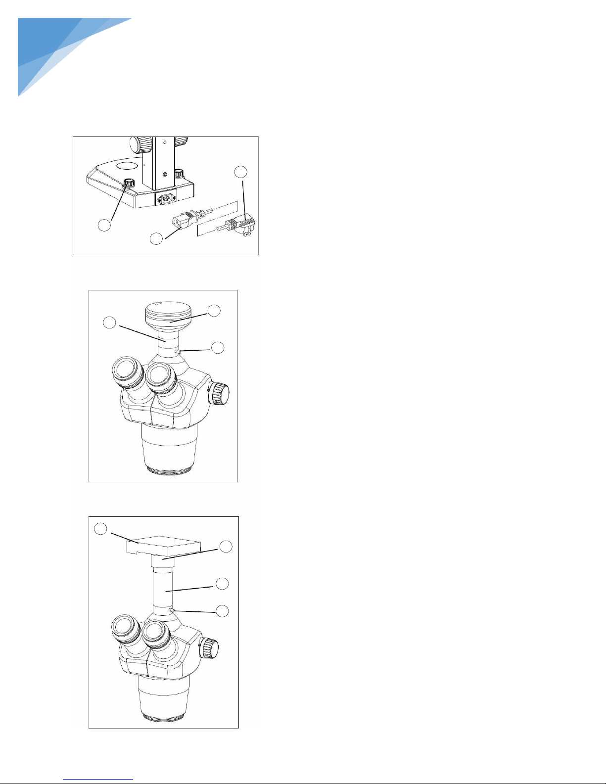
2.2.3. Connecting the power cord (Figure 4)
1. Clockwise rotate the left and right brightness adjusting
switches ① until the end on (off) state before
connecting the power cord ②.
2. The power plug ② into the power jack of the
microscope; make sure the connection is well.
3. Plug the power cord ③ into the power supply
receptacle safely. Make sure the connection is well.
Adjustable illumination for both LEDs (top and
bottom).
Input Rating: 100V~240V.
2.2.4. Video (Photography) accessories assembly
1. Installing the video set: Remove the dust cap of the
trinocular viewing tube, revolve the camera set ⑤ into
the screw thread end---the video adapter ④ with C
mount, and insert the other end into the tri-through port
and screw down the bolt ⑥.
2. Installing the photography set: Remove the dust cap of
the trinocular viewing tube, install the photography
accessories ⑦ into the tri-through port, and screw down
the locking bolts ⑥, change the camera ⑨ gun with
digital photography adapter ⑧, and insert the adapter
into the accessories, as in Fig 6.
1 2 3
4
5
6
6
7
8
9
Figure 4
Figure 5
Figure 6
STEINDORFF
Page 8
7
®
3. ADJUSTMENT AND OPERATION
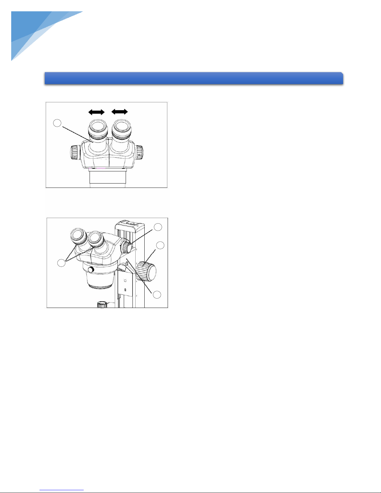
3.1.1. Adjusting interpupillary distance (Figure 7)
Different users have different interpupillary distances. So
when users change, do the interpupillary distance
adjustment.
While looking through the eyepieces, hold the left and
right of the binocular assembly ① and adjust the
eyepieces by opening or closing them for binocular vision
until the left and right fields of view coincide completely.
3.1.2. Adjusting diopter ring (Figure 8)
1. Set the diopter rings of both eyepieces to “0”position.
(Do this when users change, because different users
have different diopters.)
2. Place an easy-to-observe specimen on the stage plate.
3. Rotate the zoom body knob ③ to the highest
magnification 4.5x, and turn the focusing knob ④ to
focus the specimen.
4. Rotate the zoom body knob ③ to the lowest
magnification 0.7x, looking only into the left eyepiece,
adjust the diopter ring on left eyepiece to focus the
specimen. Then do the same thing for the right one.
5. Repeat item 3 and 4 until the specimen image can
always focus without any adverse effect of the changes
of magnification on the definition of the image.
The working distance of the microscope is 97mm, the
binocular head bracket ⑤ could be mounted onto the
higher or lower position according to your needing.
Remove the clamping bolt with provided hexagonal
driver and move the bracket ⑤ down to the lower
position and set it with original bolt (Figure 8).
1
2
3
4
5
Figure 7
Figure 8
STEINDORFF
3.1. Adjusting Binocular Viewing Head
Page 9
8
®
Figure 9
Figure 10
1 2 3
4
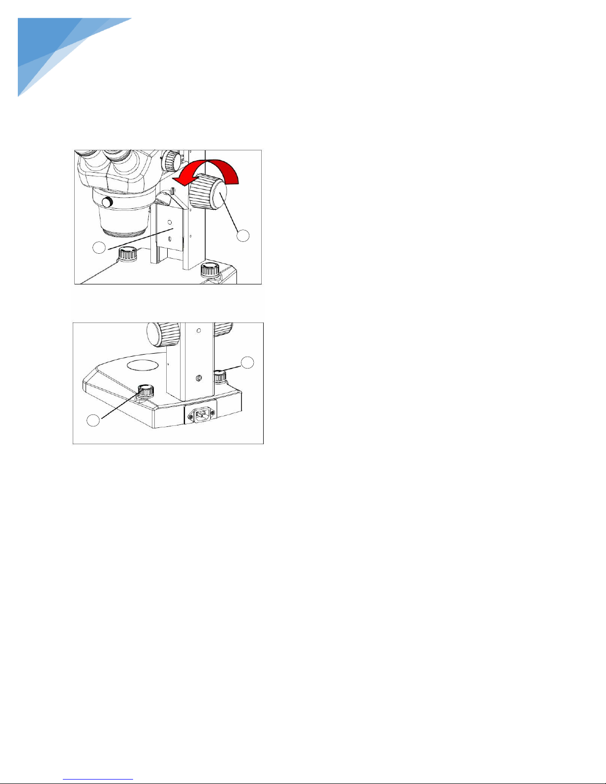
3.2.1. Adjusting the rotation tension of the focus adjustment
knob (Figure 9)
1. Rotate the focus adjustment knob ① to move the slider
② to a lower place for fear that the zoom body drops
down suddenly if the tension is decreased too much.
2. Hold the focus adjustment knobs ① with both hands,
stop the left knob and rotate the right knob to increase or
decrease the focus knob tension.
3. Rotate two sides of the adjustment knobs in the same
direction (otherwise it will get loose) to move the zoom
body up and down to focus on the specimen.
3.2.2. Changing the magnification
1. The zooming knots located at two sides of the zooming
body could change the magnification of the specimen
image.
2. Total Magnification = Magnification of zoom body ×
magnification of eyepiece
While using the auxiliary objective, it should be
multiplied by its magnification in addition.
STEINDORFF
3.2. Focus Adjustment
3.3. Illumination (Figure 10)
1. Adjustable illumination for both LEDs (top and bottom).
2. Brightness adjustment: the right brightness adjustment knob ③ is used to adjust the bottom illumination,
and the left brightness adjustment knob ④ is used to adjust the top illumination. Each knob have its own
on-off. Rotate anticlockwise to open the power, and continue would increase the brightness, keeping
rotating clockwise would decrease the brightness until it is power off.
Page 10

9
®
Auxiliary
Objective
Working
Distance
(mm)
Eyepiece
10x/20mm
15x/16mm
20x/12mm
Magnification
Actual Field
Magnification
Actual Field
Magnification
Actual Field
No
97
10 - 45x
Φ20 - Φ4.4
15 - 67.5x
Φ16 - Φ3.56
20 - 90x
Φ12 - Φ2.67
0.75x
120
7.5 - 33.75x
Φ26.7 - Φ5.9
11.25 - 50.63x
Φ21.3 - Φ4.74
15 - 67.5x
Φ16 - Φ3.56
2x
30
20 - 90x
Φ10 - Φ2.2
30 - 135x
Φ8 - Φ1.78
40- 180x
Φ6 - Φ1.33
PROBLEM
CAUSE
SOLUTION
Incomplete binocular vision.
Interpupillary distance is not
correctly adjusted.
Adjust it correctly
Diopter adjustment is incomplete.
Complete diopter adjustment
Dirt is visible in field of view
Dirt on specimen
Clean specimen
Dirt on eyepiece
Clean eyepiece
The visibility of the image is poor.
Dust on objective front lens.
Clean lens surface
Specimen image blurs when zoom
magnification is changed.
Diopter ring is not correctly
adjusted.
Adjust it correctly.
Not in complete focus on specimen.
Focus specimen correctly at a high
magnification.
Coarse focus adjustment knobs
rotate with too much resistance.
Tension adjustment ring is too tight.
Loosen it properly.
Zoom microscope body drops or
specimen goes out of focus during
observation.
Tension adjustment ring is too
loose.
Tighten it properly.
4. SPECIFICATION
5. TROUBLESHOOTING
STEINDORFF
4.1. Zoom ratio: 1:4.5
4.2. Objective magnification: 1x~4.5x
4.3. Binocular viewing head: Inclined at 45˚, interpupillary distance range: 55~75mm
4.4. Working distance: 97mm
4.5. Illumination system: Adjustable illumination for both LEDs (top and bottom)
Under certain conditions, performance of this unit may be adversely affected by factors other than defects. If a
problem occurs, please review the following list and take remedial action as needed. If you cannot solve the problem
after checking the entire list, please contact your local franchiser for assistance.
Page 11

10
®
Components
Specification
Quantity
Outfit
Main body
Main body
1
●
Observation system
Binocular head and
zoom body
1:4.3
1
○
1:4.5
1 ● Trinocular head and zoom body
1
○
Illuminator
Transmitted illuminator (LED)
1 ● Reflected illuminator (LED)
1
●
Eyepiece
10x Eyepiece
2
●
15x Eyepiece
2
○
20x Eyepiece
2
○
Auxiliary objective
0.75x Objective
1
○
2x Objective
1 ○ Digital camera
1 ○ Camera adapter
1
○
Stage plate
Glass plate
1
●
Power cord
Power cord
1
●
6. OUTFIT
STEINDORFF
 Loading...