

Page 1
®
STEINDORFF
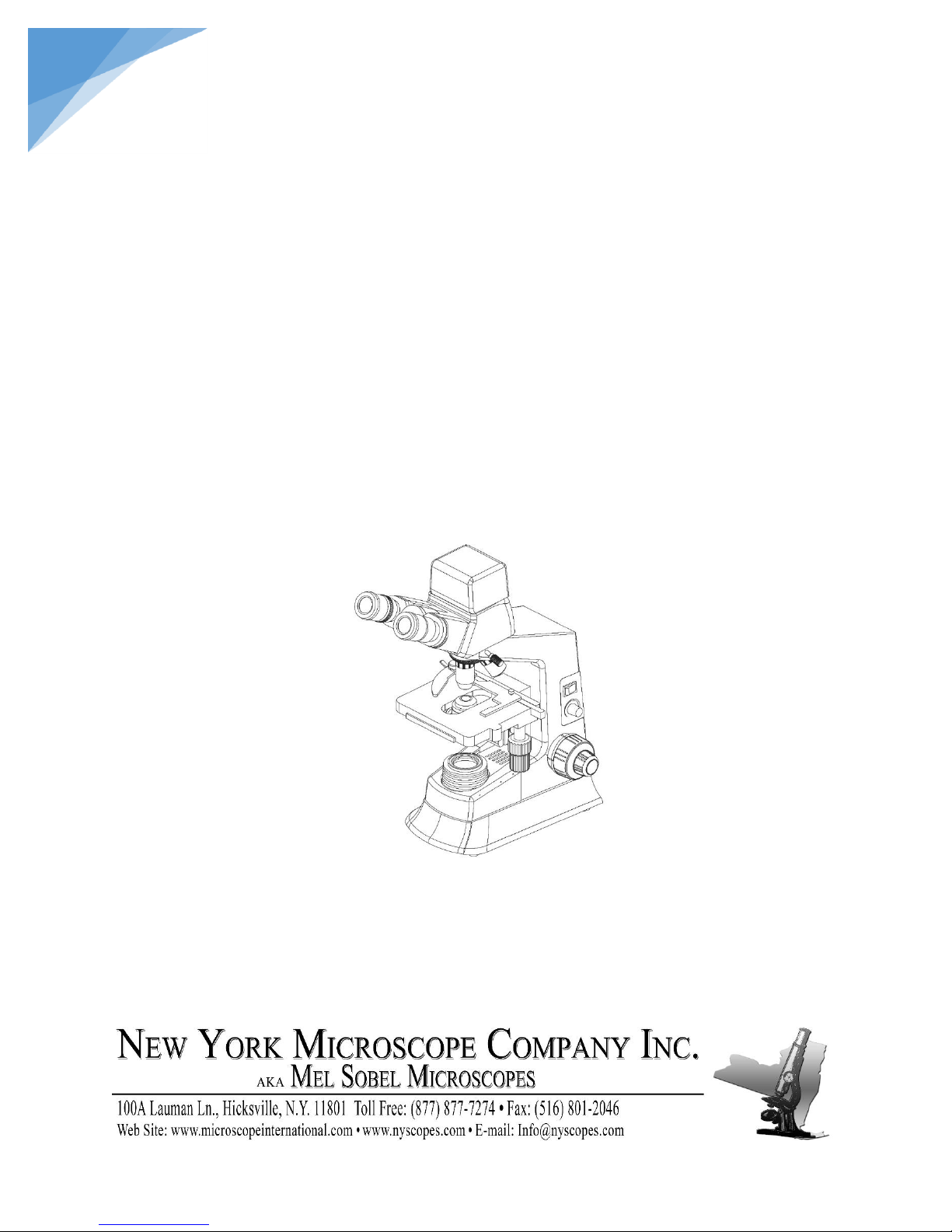
Biological Microscope
NYMCS-237
Instruction Manual
This manual is written for biological microscope NYMCS-237 series. To ensure the safety, obtain
optimum performance and to familiarize you fully with the use of this microscope, it is recommended
strongly that you study this manual thoroughly before using the microscope and retain this manual in an
easily accessible place near the work desk for future reference.
Page 2

1
®
USER NOTICE
STEINDORFF
I. Safety Notes
1. Carefully open the box, avoid the accessories, like lens, dropping to ground and being
damaged.
2. Do keep the instrument out of direct sunlight, high temperature or humidity, dusty and easy
shaking environment. Make sure the stage is smooth, horizontal and firm enough.
3. When moving the instrument, please use two hands to grip with the two sides of the
microscope body.
4. During use, if the microscope is splashed by liquid, cut off the power at once, and wipe away
the splash.
5. When running, the lamp house and nearby parts will be very hot. Please ensure there is
enough cooling room for them.
6. Make sure the instrument is earthed, to avoid lighting strike.
7. For safety, be sure the main switch is in “O” (off) state before replacing the halogen lamp or
the fuse, then cut off the power, and do the operation after the lamp bulb and the lamp house
completely cool down. (Specified: Halogen Lamp 6v 20w or LED 3w)
8. Check the input voltage: be sure the input voltage which signed in the back of the microscope
is consistent with the power supply voltage, or it will bring a serious damage to the
instrument.
9. - Warning against high temperature.
10. - Warning against electric shock.
11. - Warning: before use, carefully read the manual .improper use could result in personal
injury to the user and/or damage to the equipment
II. Maintenance
1. All the lenses have been well checked and adjusted. It is forbidden to disassemble them
yourself.
2. The nosepiece and coarse/fine focus unit have a compact and precise frame, so please
don’t disassemble them as possibly as you can.
3. Keep the instrument clean, wipe dust regularly, and be attention to avoid contaminating
the optical elements especially.
4. The contaminations on the prism, as finger mark and oil, could be gently wiped with a
piece of soft cloth or tissue paper, gauze which has been immersed in pure alcohol or
ether. (Note that the alcohol and ether are highly flammable, do keep them away
from the fire or potential sources of electrical sparks, and use them in a drafty room
as possible as you can.)
Page 3

2
®
STEINDORFF
5. Do not attempt to use organic solvents to clean the microscope components other than the
glass components. To clean them, use a lint-free, soft cloth slightly moistened with a
diluted neutral detergent.
6. When using, if the microscope is splashed by liquid, cut off the power at once, and wipe
up the moisture.
7. Do not disassemble any parts of the microscope, which will affect the function or decline
the performance of the microscope.
8. Place the instrument in a cool, dry position. When not using the microscope, keep it
covered with a dust cover. Make sure the lamp socket is cool before covering the
microscope.
Page 4
3
®
Magnification
Numerical
Aperture
(N.A.)
Thickness of
coverslip
(mm)
Focal length
(mm)
Working
distance (mm)
Type
4x
0.10
0.17
28.902
17.912
Dry
10x
0.25
0.17
16.6
5.6
Dry
40x
0.65
0.17
4.28
0.6
Dry
100x
1.25
0.17
1.82
0.14
Oil
Category
Magnification
Focal length (mm)
Field of view (mm)
Wide field eyepieces
10x
24.86
Φ20
Plan eyepieces
16x
15.58
Φ11
Eyepieces
10x
16x
10x
16x
10x
16x
10x
16x
Objectives
4x
10x
40x
100x
Total
Magnification
40x
64x
100x
160x
400x
640x
1000x
1600x
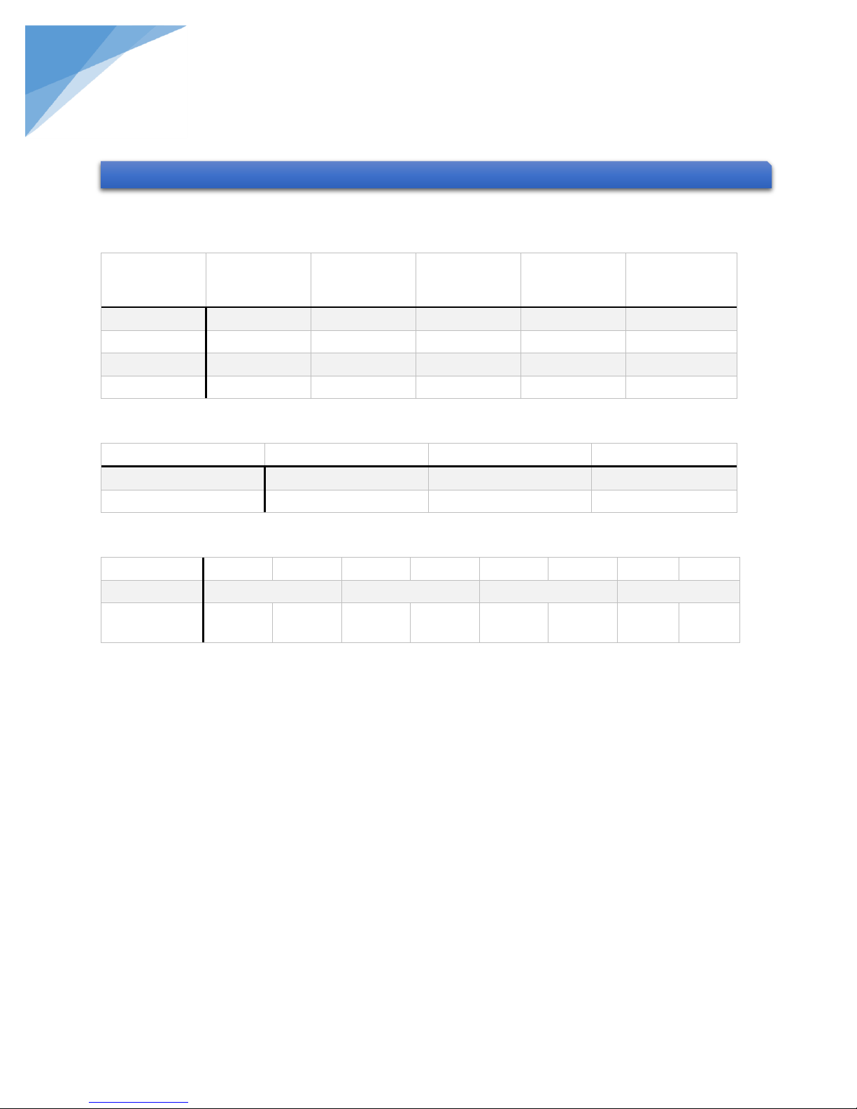
1. SPECIFICATIONS
STEINDORFF
1.1. Mechanical tube: 160mm
1.2. CF high-contrast objectives:
1.3. Eyepieces:
1.4. Total Magnification:
1.5. Conjugate Distance: 195mm
1.6. Compensation free binocular head: inclined at 30°
1.7. Double layers mechanical stage: 140mm x 140mm
Moving Range: 75mm x 50mm
1.8. Coaxial coarse & fine focusing system, Adjustment Range: 20mm
Fine Division: 0.002mm
1.9. Condenser: N.A. = 1.25 Abbe condenser with iris Diaphragm, Adjustment Range: 20mm
1.10. Illumination system: halogen lamp 6v 20w or 3w LED, Brightness Adjustable, Voltage
Rating: 110v or 220v
Page 5
4
®
2. MICROSCOPE FRAME
STEINDORFF
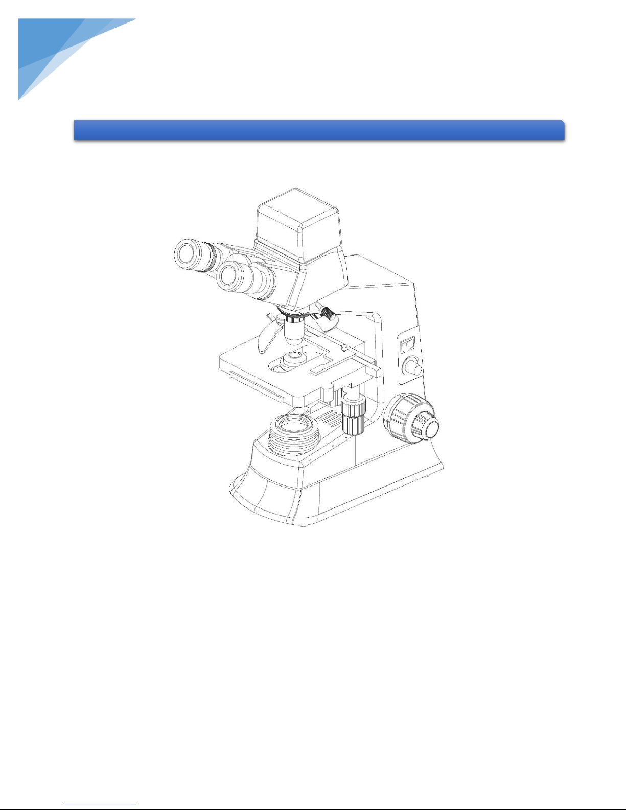
Viewing head:
Compensation free binocular viewing head, inclined at 30°, interpupillary distance: 48-75mm.
Camera system:
External digital camera system with C-mount, 1.3M pixel CMOS image sensor.
NYMCS-237 Digital Biological Microscope
Page 6
5
®
3. ASSEMBLY
③
①
② ④
Plan eyepieces
Objectives
Power cord
Main body
⑤
STEINDORFF
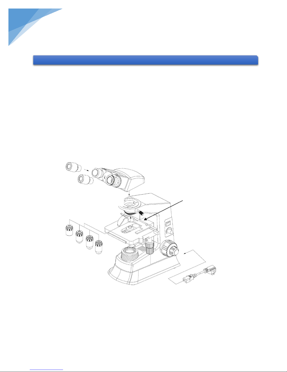
3.1. Assembly Diagram
The following figure shows the installation sequence of the components. The number in the
figure shows the assembly steps.
Before installing, be sure every components is clean, do not scratch any parts or
glass surface.
Keep well with hexagon wrench provided. When replacing the components, you
will need it again.
Page 7
6
®
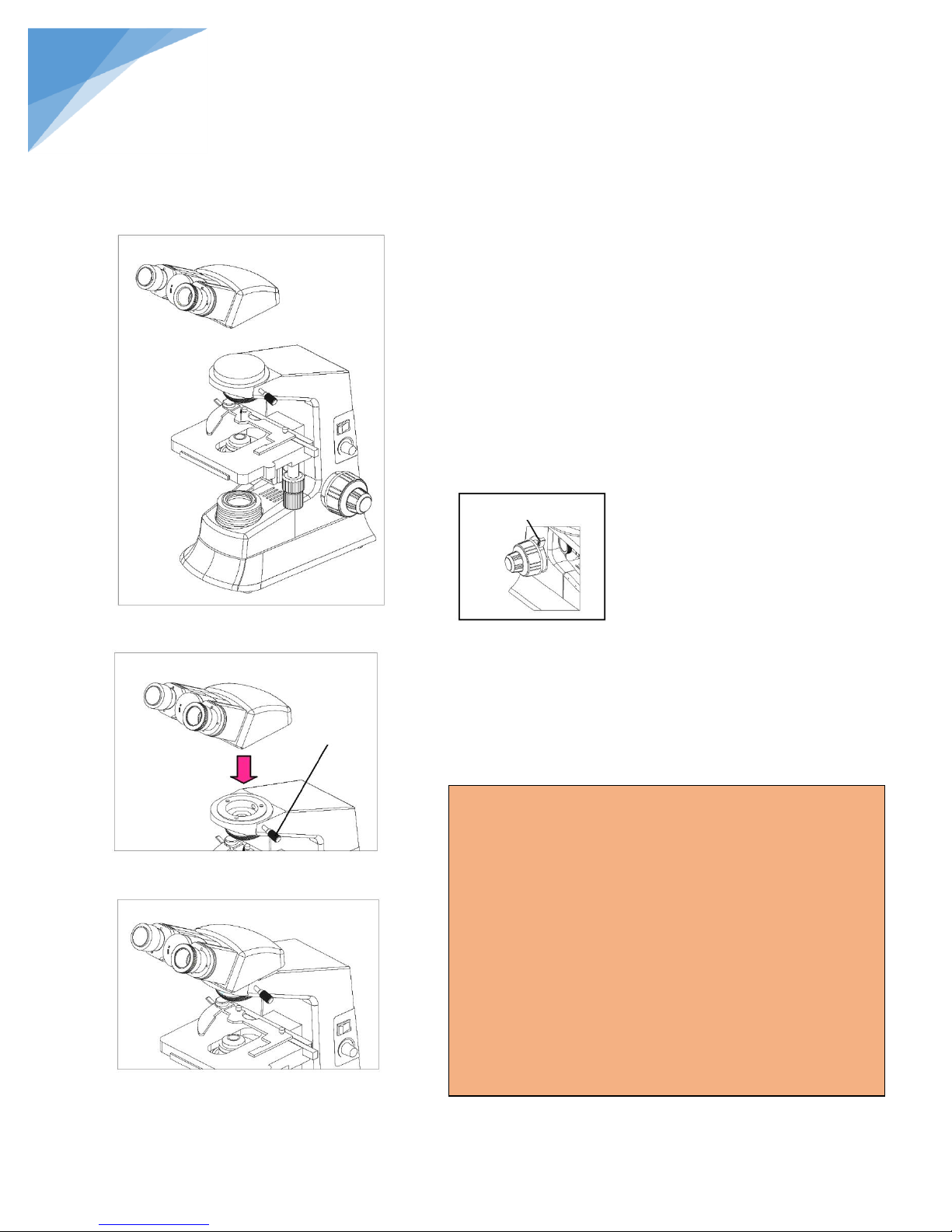
3.2.1. Preparation (Fig. 1)
For protecting the microscope in shipping, we took some
protect measures, so you need to finish the things listed
below before installation: ① move away the plastic cap on
the binocular viewing head; ② move away the plastic cap
on the microscope body; ③ move away the plastic envelop
of the stage; ④ revolve the adjustment knob upwards
(firstly, please revolve the leftward knob up to loosen),
remove the fixed block which used to prevent the stage
slipping.
3.2.2. Installing binocular viewing head (Fig. 2, Fig. 3)
Insert the compensation free binocular head into the
microscope body, turn into the right position, then screw
down the bolt ⑤ to fix it.
Note:
Operation Conditions:
1. Temperature :0° C~40° C, Maximum Relative
Humidity: 85%.
2. High Temperature: High Temperature and humidity
will result in a mildewing, dew and even ruinous
instrument.
3. Avoid placing the instrument in a dusty
environment. When ending your microscope
operation, please cover it with the dust cap.
4. Lay the microscope in a plan and stable position,
please.
Fig. 1
Left Locking Knob
Fig. 2
Fig. 3
⑤
STEINDORFF
3.2. Assembly steps
Page 8
7
®
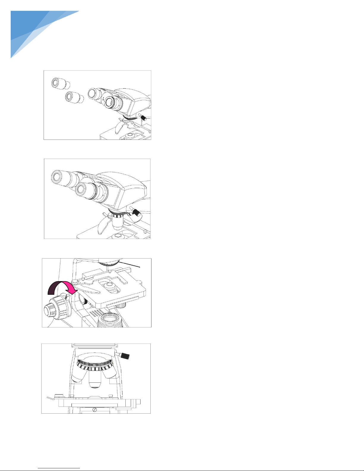
3.2.3. Installing the eyepieces (Fig. 4, Fig. 5)
Insert the eyepieces into the eyepiece tube until they are
against each other as shown in Fig. 5.
3.2.4. Installing objectives (Fig. 6, Fig. 7)
1. Adjusting the coarse focus knob until the support
device of the mechanical stage reaches its low limit
position.
2. Screw the lowest magnification objective into the
nosepiece ① from the left or right side, then
revolve the nosepiece clockwise and mount the
other objectives in sequence of low to high
magnification.
Clean the objectives regularly, for lens is
susceptible to dust.
When operating, use the 10x objective to search
and focus on the specimen, then replace with
higher magnification if necessary.
Turn the objective until hear a “click” sound,
indicating the objective is in the required
position – center of light path.
Fig. 4
Fig. 5
Fig. 6
Fig. 7
①
STEINDORFF
Page 9
8
®
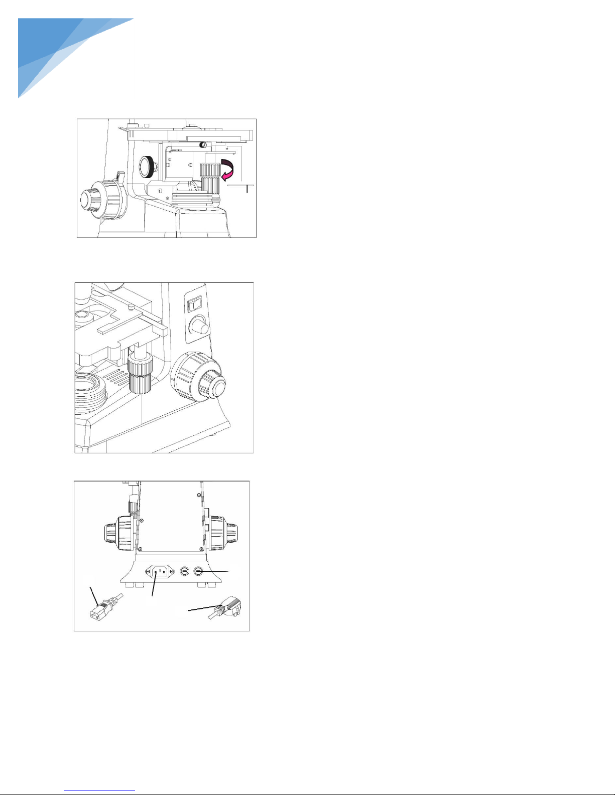
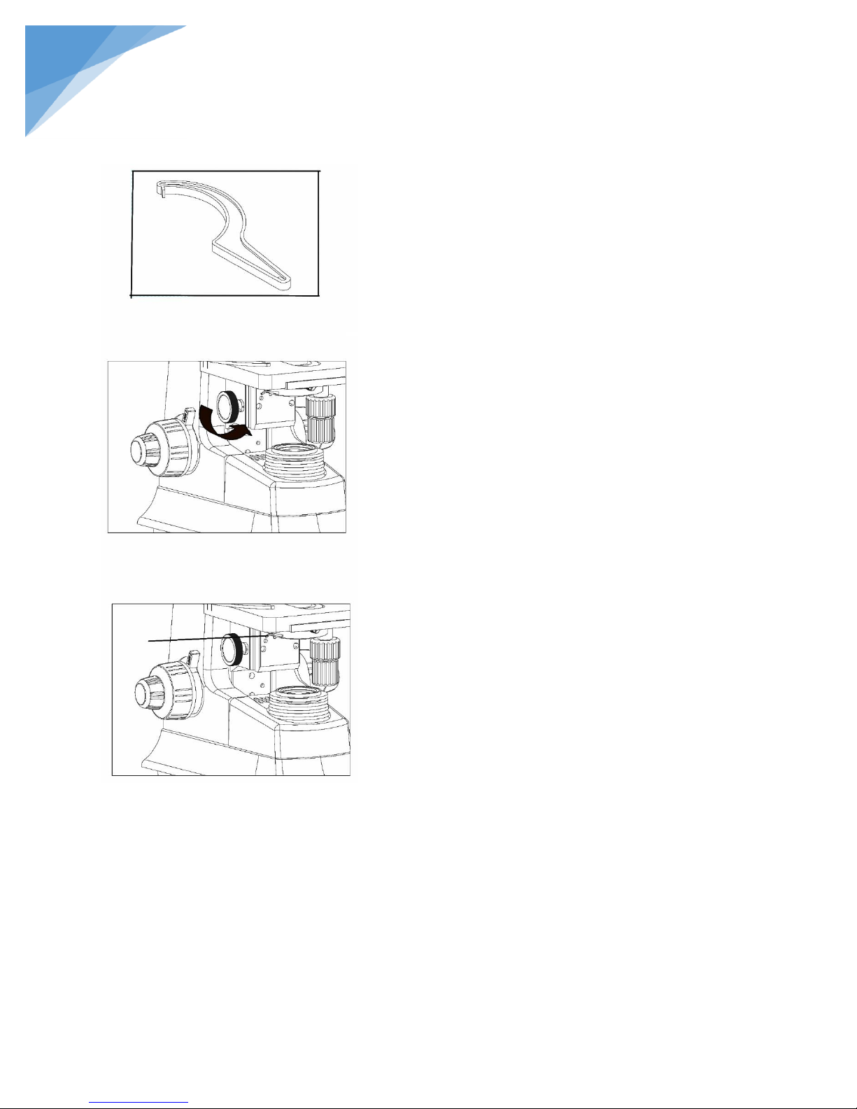
3.2.5. Installing the color filters (Fig. 8)
1. Pressing the salient point under the condenser
bracket, turn the condenser bracket ① out at the
direction of arrow in Fig. 8
2. Put the required filters into the holder on the
bracket, and then turn the bracket back to the right
position.
Baby blue and green filters are available in
standard outfit.
3.2.6. Connecting the power cord (Fig. 9, Fig. 10)
1. Turn the main switch ① to “O” (off) state before
connecting the power cord.
2. Insert the power plugs ② into the power jack ⑤
of the microscope; Make sure the connection is
well.
3. Plug the power cord ③ into the power supply
receptacle safely. Make sure the connection is well.
Make sure to check the input voltage, see
whether or not it is the same as the nameplate
indicates. Using the wrong input voltage would
result in a short circuit or fire, and destroy the
instrument.
Use the supplied power cord at all times. If lost
or damaged, please select the same standard
power cord.
3.2.7. Replacing the fuse (Fig. 9, Fig. 10)
Remember to turn the main switch ① to “O” (off) before
replacing the fuse, and unplug the power cord. Rotate the
fuse kit ④ out of the holder by the “–” type screwdriver,
replace the fuse and reinsert the holder.
This instrument has two fuses, the rating is:
250V, 500mA
Fig. 8
Fig. 9
Fig. 10
③
② ④
⑤
Filter
STEINDORFF
Page 10
9
®
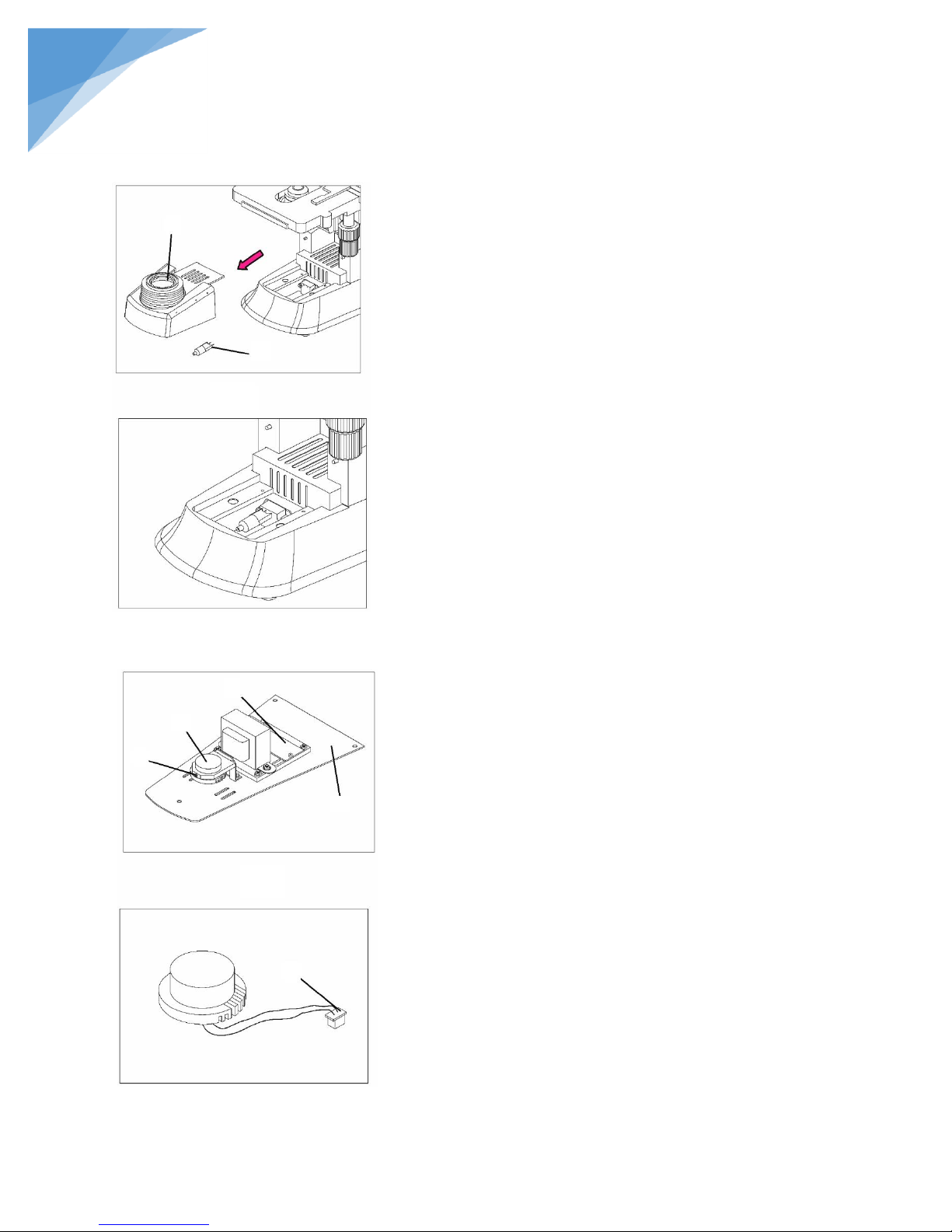
3.2.8. Replacing the Lamp (Fig. 11, Fig. 12)
1. Please set the main switch to “O” state (off) before
replacing, and make sure the bulb, the lamp room
and periphery are all cool enough to carry no burn.
Then, you can do your replacing.
2. Take up the collector holder ① lightly, pull it out
by the direction which the figure shown.
3. Pull out the old bulb ②, hold the new bulb after
you wrap it with gauze or other protection materials
and insert its pin as deeply as possible into the jack
in the lamp holder.
4. Insert the condenser holder back to the microscope
body, pushing down to make sure the holder is
holed stable enough.
Please insert the bulb gently, or it will be
damaged by excessive extrusion.
Do not touch the halogen bulb with bare hands.
It will shorten the service life or cause it to
burst. If you leave fingerprints on the surface
carelessly, clean it with a piece of dry soft cloth.
When replacing LED:
1. Generally, the LED has a long service life and is
not easily damaged. If damaged, purchase a new
one from your supplier. (Fig. 14)
2. Remove the base plate ③ from the bottom of the
microscope with screw driver, remove screw ④ to
take off the old LED, pull out the other end of LED
wire from the breadboard ⑥, and replace with the
new LED.
3. Put the new LED unit back onto the bracket with
the screw ④ and insert the end of the LED wire
onto the breadboard ⑥.
4. Install the base plate ③ back onto the bottom of
the microscope with original screws.
When removing the base plate, please do so
gently and slowly, to avoid damaging internal
electrical wires.
Fig. 11
Fig. 12
Fig. 13
Fig. 14
③
② ④
⑤ ① ⑥
⑦
STEINDORFF
Page 11
10
®
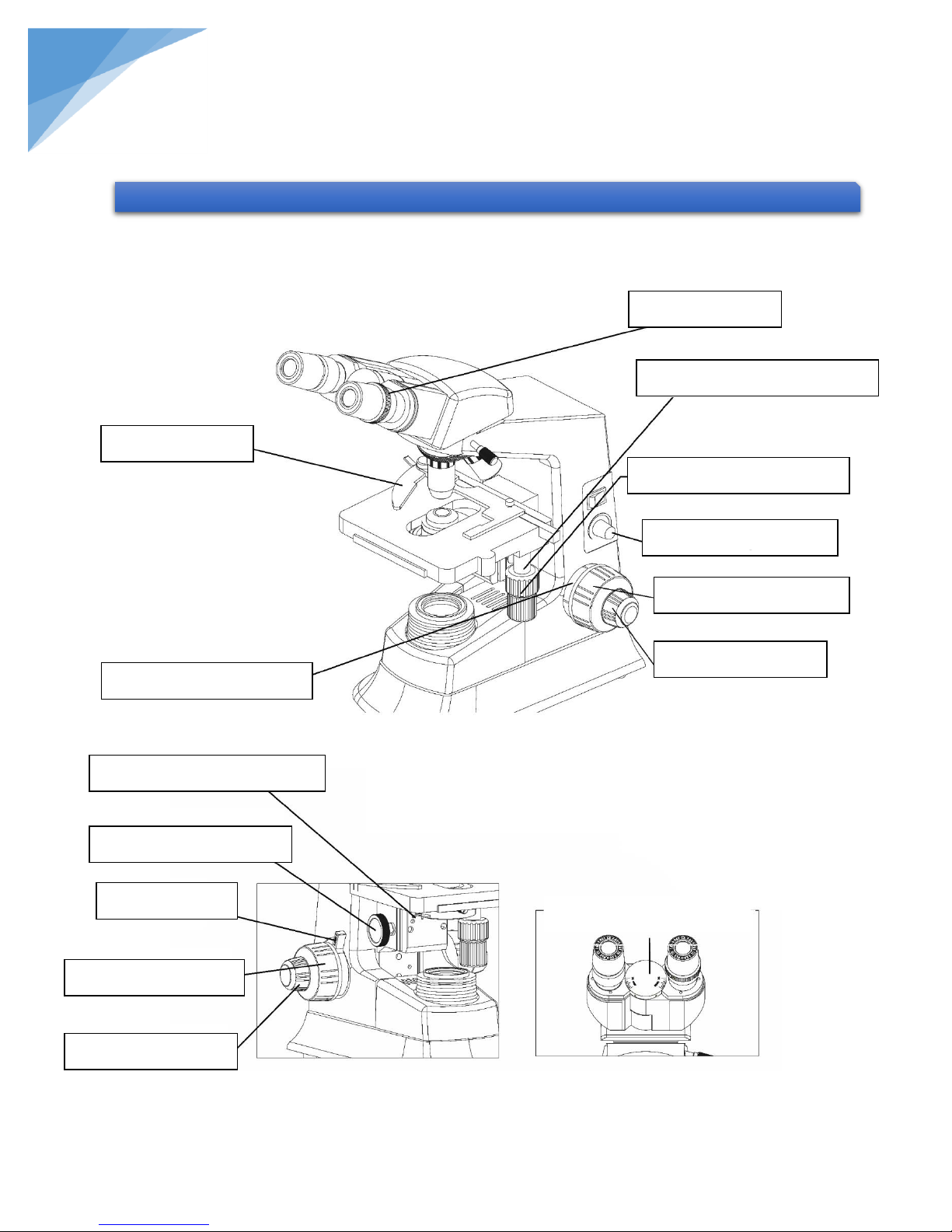
4. ADJUSTMENT & OPERATION
Fig. 15
Fig. 16
Fig. 17
Diopter ring
Longitudinal Adjustment Knob
Transversal Adjustment Knob
Brightness Adjustment
Right Coarse Focus Knob
Right Fine Focus Knob
Specimen holder
Tension Adjustment Collar
Aperture diaphragm adjust lever
Condenser Focusing Knob
Locking Set
Left Coarse Focus Knob
Left Fine Focus Knob
Interpupillary Distance Indicator
STEINDORFF
4.1. Assembly Diagram
Page 12
11
®
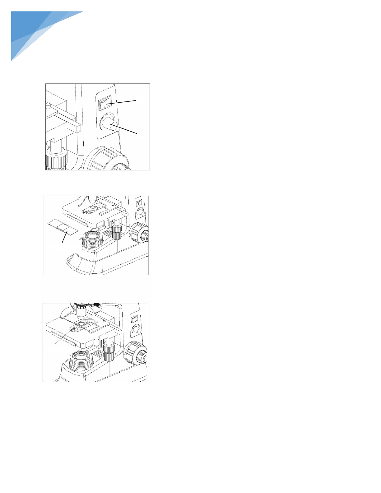
4.2.1. Adjusting the brightness (Fig. 18)
1. Connect the power, turn on the main switch ①
(shown on the figure) which on the bottom side of
the base to “-” (on).
2. Turning the brightness adjustment knob ②
clockwise, the voltage raise, and the brightness
strengthen; whereas turning at the contra direction,
the voltage decline, and the brightness weaken.
The brightness is affected by kinds conditions,
like the phase contrast of the specimen, the
magnification of the objective, the adjust ability
of the eyes and so on. Too faint or too strong
light is not suitable. So, generally you should not
adjust the brightness to the highest intensity, or
it will let the lamp working in a fully loaded
state, and bring a shorten work life.
4.2.2. Placing the specimen (Fig. 19, Fig. 20)
1. Place the specimen on the center of the stage,
keeping the cover slip upward, and then nip it with
the specimen holder.
2. Turn the longitudinal and transversal adjustment
knobs which are on the mechanical ruler to move
the specimen into the required position.
Be careful when changing the objective. If you
finish observation with the short working
distance objective, and want to change to
another one, be careful not to let the objective
touch the specimen.
Fig. 18
Fig. 19
Fig. 20
Specimen
Cover Slip
② ①
STEINDORFF
4.2. Operation
Page 13
12
®
Note:
Only a little oil is needed. If too
much, the residual oil will seep
into the stage and the condenser
and result in a decline of the
performance.
Fig. 21
Fig. 22
STEINDORFF
4.2.3. Oil spacing observation
The objective labeled “Oil” is oil immersion objective (100x objective). When use the oil-spaced
lens, you need to add special oil only used for microscope between the objective and the cover slip.
You should be aware of the cleaning procedures to be used after the use of oil. Wipe oil from the oil
immersion objective, and from any other parts in need of cleaning. Clean lenses immediately after
use. Leaving oil on the lens may allow oil to seep behind and harden on the inside of the lens
Immersing the oil
Add oil between the objective and the specimen, note that not
all kinds oil are suitable, it is a special one, just supplied for
microscope. (Cedar oil Fig. 21)
Eliminating the bleb
The bleb in the oil will result in a bad effect on the image
quality. So make sure there is no bleb when using the oil. You
also can take the following steps to avoid this problem:
o Turn the nosepiece gently to move the oil immersion
objective several times.
o Add more immersion oil
o Wipe away the oil, and add some other oil for
replacement
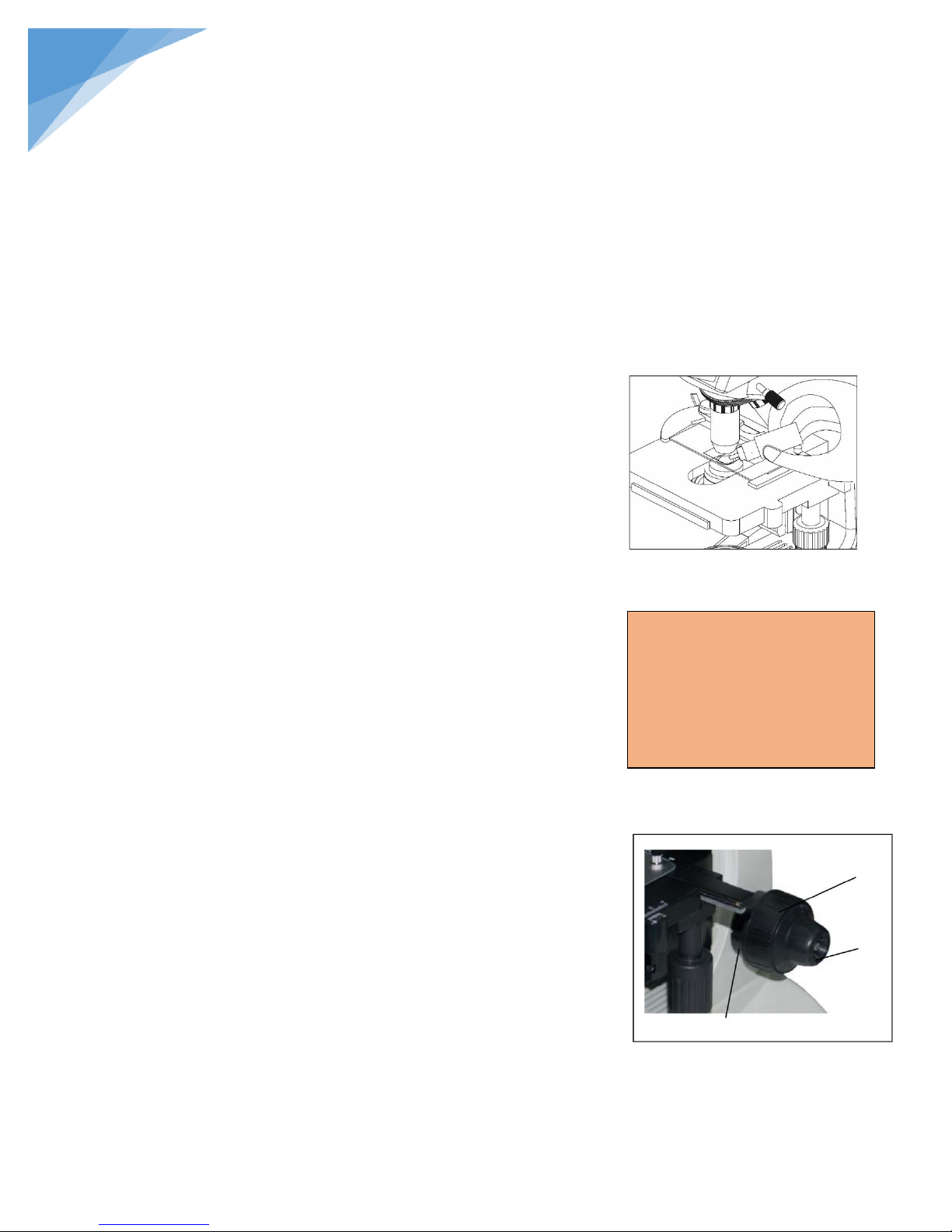
4.2.4. Focus (Fig. 22)
Place the specimen on the center of the stage, make sure the cover slip is
upward, then, uses the 10x objective and the 10x ocular to perform the
observation.
To avoid the objective touching against the specimen, you should rise the
mechanical stage up to make the specimen near to the objective at first,
then apart them slowly to make focus.
When focusing, please reversely turn the coarse focus knob ①, let the
specimen falling slowly, and look into the ocular to search image at the
same time. And at last, change the fine focus knob ② to sharp the image.
After done this, you could change other magnification objective freely
with no risk of damaging the specimen.
Page 14
13
®
The tight tension of the coarse focus knob has
already been adjusted before leaving factory. If
loosen (e.g. the stage slip down by its weight),
please screw the intention adjustment collar ③
to the right position by the supplied spanner.
4.2.5. Condenser Adjustment (Fig. 23)
Turn the condenser focus knob to move the condenser up
and down. Raise the condenser when using the high
magnification objective, and lower it when using the low
magnification objective.
The condenser and the objective are coaxial. It
has been adjusted well before leaving the
factory, so the user nee not adjust them.
The highest position of the condenser has also
been adjusted. User adjustment is not needed.
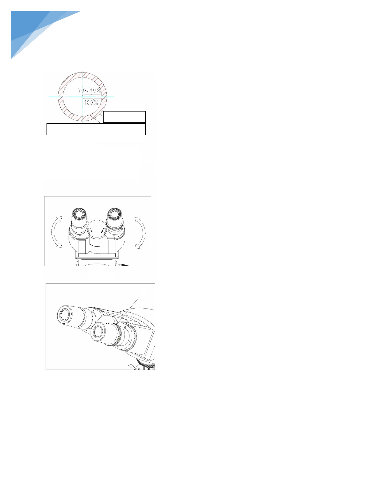
4.2.6. Aperture Iris Diaphragm Adjustment (Fig. 25)
Turn the aperture iris diaphragm lever ① to adjust the
aperture iris diaphragm.
If the size of the aperture diaphragm minified,
the brightness and resolution declined, while the
contrast and depth of field increased; In other
words, if the size is enlarged, the brightness and
the resolution improves, but the contrast and
depth of field declines.
Generally, setting the size of the condenser
aperture diaphragm at 70% ~ 80% of the
numerical aperture, you can obtain a clear
image with enough contrast. If the opening of
the aperture diaphragm is too small, the
resolution will be very low, please do not minify
the aperture below 60% of the numerical
aperture.
Fig. 23
Fig. 24
Fig. 25
①
STEINDORFF
Page 15
14
®
The numerical aperture is marked on the
objective. For example, the mark “10/0.25”
means the magnification is 10x,and the
numerical aperture is 0.25.
If you want to observe the image of the aperture
iris diaphragm, remove one eyepiece and look
through the tube. You will see a dark circle
encroaching on the bottom of the tube.
4.2.7. Adjusting the Interpupillary Distance (Fig. 27)
Interpupillary distance range: 55mm ~ 75mm
When observing with two eyes, hold onto the left and right
prism holders, turn then around the axis to adjust the
interpupillary distance until the lift and right fields of view
coincide completely, as shown in Fig. 27.
4.2.8. Adjusting the diopter (Fig. 28)
1. Look into the left ocular with your left eye, then
revolving the coarse knob to focus on the
specimen.
2. Then use the right eye to look into the right ocular.
If the image is not sharp, use the diopter
adjustment ring ① to adjust.
Fig. 27
Fig. 28
Fig. 26
The right size of the aperture
①
Specimen
Image of Aperture Iris Diaphragm
STEINDORFF
Page 16

15
®
Components
Specifications
S-237
Main Body
Main body
●
Double layers mechanical stage
●
Condenser bracket
●
Viewing Head
Compensation Free Binocular Head, Inclined at 30°
●
1.3M Pixel CCD Camera System
●
USB Cable
●
Condenser
N=1.25 Abbe Condenser with iris diaphragm
●
Nosepiece
Quadruple
●
Quintuple
○
Illumination System
3W LED
●
Kohler illumination system
○
Spare bulb (6v 20w halogen lamp)
○
Spare fuse, with rating: 250mA (500mA for 110V)
●
Eyepieces
EW10x WF eyepieces
●
WF16x WF eyepieces
○
Objectives
CF high-contrast objectives
4x
●
10x ● 40x ● 100x
●
Plan achromatic objectives
4x, 10x, 20x, 40x, 60x, 100x
○
Filters
Baby blue
●
Green
●
Polarization Set
Simple Polarization Set
○
Phase Contrast Kit
Simple Phase Contrast Kit
○
Sliding Phase Contrast Kit
○
Turret Phase Contrast Kit
○
Dark Field Condenser
Dry dark field condenser NA 0.9
○
Oil dark field condenser NA 1.25 - 1.36
○
Fluorescent attachment
Epi-fluorescent attachment
○
Pointer system
LED Optical Point System
○
Note: ● Standard, ○ Optional
5. OUTFIT
STEINDORFF
Page 17

16
®
PROBLEMS
REASON FOR PROBLEMS
SOLUTION
I. Optical Parts
The edge of the field of
view has shadow or the
brightness is
asymmetry
The nosepiece is not in the located position
Adjust it into the located position
The filament Imaging not in center
Adjusting it to center
Stains on the lens (Condenser, Objective,
Eyepiece)
Wipe up
Stains in View Field
Stains on the lens (Condenser, Objective,
Eyepiece)
Wipe up
Stains on the specimen
Wipe up
The Condenser position is too low.
Loose the condenser locking bolt. Adjust
the position of condenser. Screw down
the locking bolt.
Low image quality
(Low resolution, low
contrast)
No cover slip on the specimen
Cover the slip
The cover slip is too thick or too thin.
Use standard cover slip.
Thickness: 0.17mm
The specimen is reversed.
Reverse back.
The dry objective is stained with oil
(Especially 40X)
Wipe up
Stains on the lens (Condenser, Objective,
Eyepiece)
Wipe up
The oil objective is not in oil.
Use oil
There is air bubble in oil
Remove oil
Not use the appointed oil
Use the appointed oil
The opening of Aperture diaphragm is too
large
Properly make it smaller
Stains on the incidence lens in the
binocular drawtube.
Wipe up
The opening of Aperture diaphragm is too
small
Properly make it larger
Condenser position is too low
Adjust the position
One side of image is
dark.
The condenser is not in center of the view
field, or the condenser is inclined.
Reinstall the condenser and adjust the
center carefully by using the condenser
adjusting bolt.
The nosepiece is not in the located position
Turn it into the required position
The specimen is floating on the stage.
Reinforce it reliably.
6. TROUBLESHOOTING
STEINDORFF
Page 18

17
®
The image moved when
focusing.
The specimen is floating on the stage.
Reinforce it reliably.
The nosepiece is not in the located position
Turn it into the required position
The image takes the
yellow slightly.
Not using the color filter.
Use the blue filter.
The bright degree is not
enough
The opening of Aperture diaphragm is too
small
Properly make it larger
Condenser position is too low
Adjust the position
Stains on the lens (Condenser, Objective,
Eyepiece)
Wipe up
II. Mechanical Part
Can’t focus when use
high magnification
objective
Slice put reversed. Cover slice is too thick.
Reverse back.
Use standard cover slice. Thickness:
0.17 mm
Touch the slice when
switch the objective
from low magnification
to high one.
Slice put reversed. Cover slice is too thick.
Reverse back.
Use standard cover slice. Thickness:
0.17 mm
The specimen move not
flowing
The slice holder not nip the slice firmly.
Make it firmly
Two eyes image not in
superposition
The interpupillar distance is not correct
Adjust the interpupillar distance
correctly
The eyes are
uncomfortable
The diopter is not right
Adjust the diopter according your sight
The bright degree is not properly
Adjust the voltage of bulb.
III. Electric Part
The lamp can’t light
No power
Check the power cord, and connect them
exactly
The installation of the bulb is wrong
Install the bulb correctly
The bulb burn out
Change the bulb
The bulb burn out in a
high frequency
Not using appointed lamp. High voltage
Use an appointed lamp. If the
circumstance still not change, please
contact the maintenance part.
The rightness degree is
not enough
Not using appointed lamp. Low voltage
Use an appointed lamp. Turn up the
voltage
The light glimpse
The bulb is going to spoil
Change the bulb
The power cord have a poor contact
Check the power cord, and connect them
exactly
STEINDORFF
 Loading...