

Page 1

®
This manual is written for Inverted Fluorescence Microscope NYMCS-1701. For safety and for
keeping the best performance, making you familiar with the instrument entirely, it is strongly
recommended that you read this manual carefully before using the microscope.
STEINDORFF
Inverted Fluorescent Microscope
NYMCS-1701
User Manual
Page 2

1
®
STEINDORFF
Use Notices
1. Name of Components ………………………………………………………4
2. Installation …………………………………………………………… 5
2.1 Installation ……………………………………………………………5
2.2 Installment steps …………………………………………………………6
3. Adjustment & Operation ……………………………………………………11
3.1 Lamp adjustment for fluorescence observation ………………………… 17
3.2 Reflected observing illumination adjustment ………………………………17
3.3 Imaging Operation ………………………………………………………19
4. Outfit …………………………………………………………32
4.1 Specification …………………………………………………………32
4.2 Objective specifications …………………………………………………………33
5. Trouble shooting ………………………………………………………………34
Page 3
2
®
Symbol
Meaning
The surface is very hot, not touch by your hands
Before using, please read the instruction carefully, improper operation will result in bodily
injure or instruction malfunction.
The main switch on
The main switch off
STEINDORFF
User Notices
Safety Note
1. The epi-fluorescent attachment is a precise instrument. Open the box carefully, and avoid dropping the
accessories to ground and causing damage to them.
2. Do keep the instrument out of direct sunlight, high temperature or humidity, dusty and virations.
3. Make certain that the burner is installed correctly and all cords are connected firmly.
4. Do not open the lamp housing while it is turned on or for at least 10 minutes after it has been turned
off. Lamp housing parts are extremely hot and cause burns if touched.
5. Always be sure to ground (earth) the equipment.
6. Verify that the voltage and the frequency of the AC mains outlet match the setting of the voltage switch
and the frequency switch on the rear of the power supply unit.
7. Always use the power cord provided and make sure that the main switch is moved to “O”(OFF) before
connecting the power cord plug to the wall outlet.
8. To prevent any hazard, always turn the main switch on the power supply unit to “O” (OFF), unplug the
power cord plug from the mains outlet before replacing the burner or the fuse, and wait for at least 10
minutes before replacing the burner. (Be sure to use a GCQ-100 mercury burner.)
9. To prevent obstruction of the air flow, it is important to leave enough space around and above the lamp
housing.
Safety Symbol
Page 4

3
®
STEINDORFF
Maintenance and Storage
1. Clean all glass components by wiping gently with gauze. To remove fingerprints or oil smudges, wipe
with gauze slightly moistened with a mixture of ether (70%) and alcohol (30%).
Since solvents such as ether and alcohol are highly flammable, they must be handled carefully.
Be sure to keep these chemicals away from open flames or potential sources of electrical sparks-for
example, electrical equipment that is being switched on or off. Also remember to always use these
chemicals only in a well-ventilated room.
2. Do not attempt to use organic solvents to clean the non-optical component of the equipment. To clean
these, use a lint-free, soft cloth lightly moistened with a diluted neutral detergent.
3. Do not disassemble any part of the power supply unit as malfunction or damage may occur.
4. In order not to impair the safety of the equipment, replace the burner when the counter of NFP -1
indicates “100.00” hours. To prevent any hazard, always turn the main switch on the power supply
unit to “O” (OFF), unplug the power cord plug from the mains outlet, and wait for at least 10 minutes
before replacing the burner. High-pressure gas is sealed within the mercury burner. Thus, if it is
continued to be used after its service life expectancy, the glass tube may deform and may sometimes
rupture.
Page 5
4
®
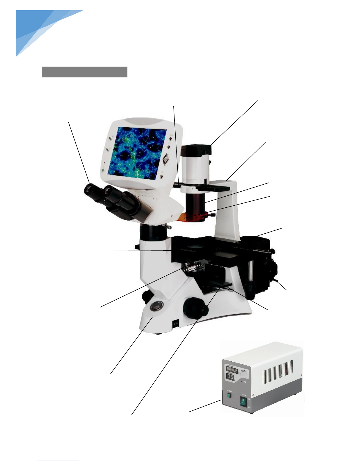
Condenser
Illumination bracket
Eyepiece
Stage inserted plate
Stage
Body
Nosepiece
Objectives
4×
10×
20×
40×
Fluorescence power supplier
Protection barrier
B excitation G excitation
Illuminator
STEINDORFF
1. Components Name
Phase contrast slider Lamp
Reflected fluorescence units
Page 6
5
®
② ④ ③ ⑤ ⑥
⑦
⑧
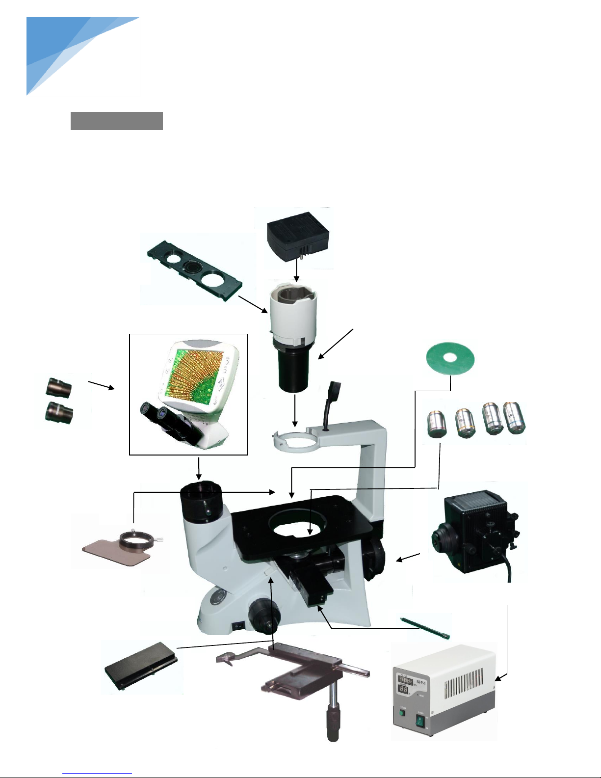
Condenser
illumination unit
Phase contrast slider
Lamp house
Eyepiece
Viewing head
Objectives
Glass stage
Power supply unit
Body Stand
⑨
⑩
⑾
⑿
Lever
Protection barrier
Mechanical ruler
①
STEINDORFF
2. Installation
2.1 Installing diagram
The following figure shows the installation sequence of the components. The number in the figure shows
the installation steps.
*Before installing, be sure every components is clean, do not score any parts or glass surface.
*Keep well with the supplied hexagon wrench. When changing the components, you will need it again.
Page 7
6
®
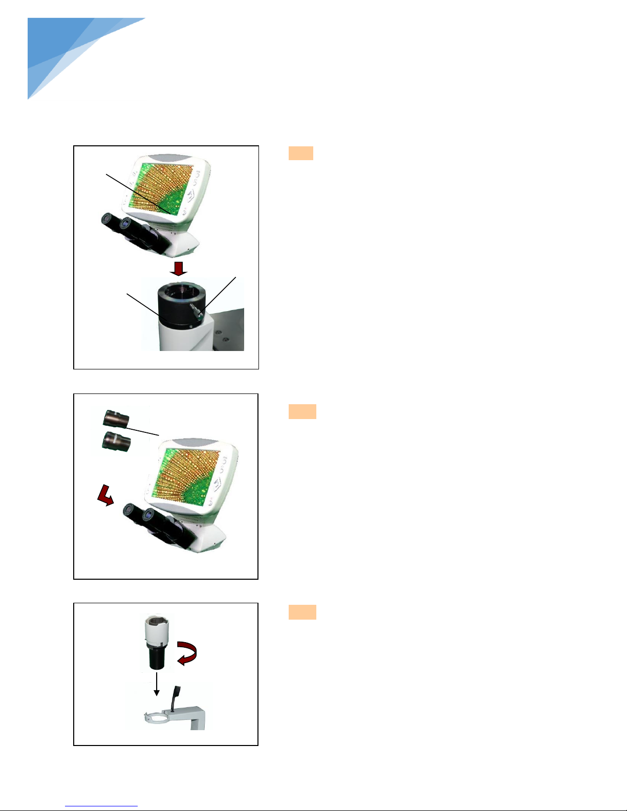
2.2.1 Installing viewing head (fig 1)
Loosen the setscrew ② and insert the Viewing Head
① into the body correctly, screw down with bolt ③.
2.2.2 Installing eyepiece (fig 2)
Insert the eyepiece ④ into tube until they are
against.
2.2.3 Installing condenser set (fig3)
Install the condenser into the right direction (fig3).
Fig 1
Fig 2
②
①
③
④
Fig 3
STEINDORFF
2.2 Installment steps
Page 8
7
®
Fig 4
A
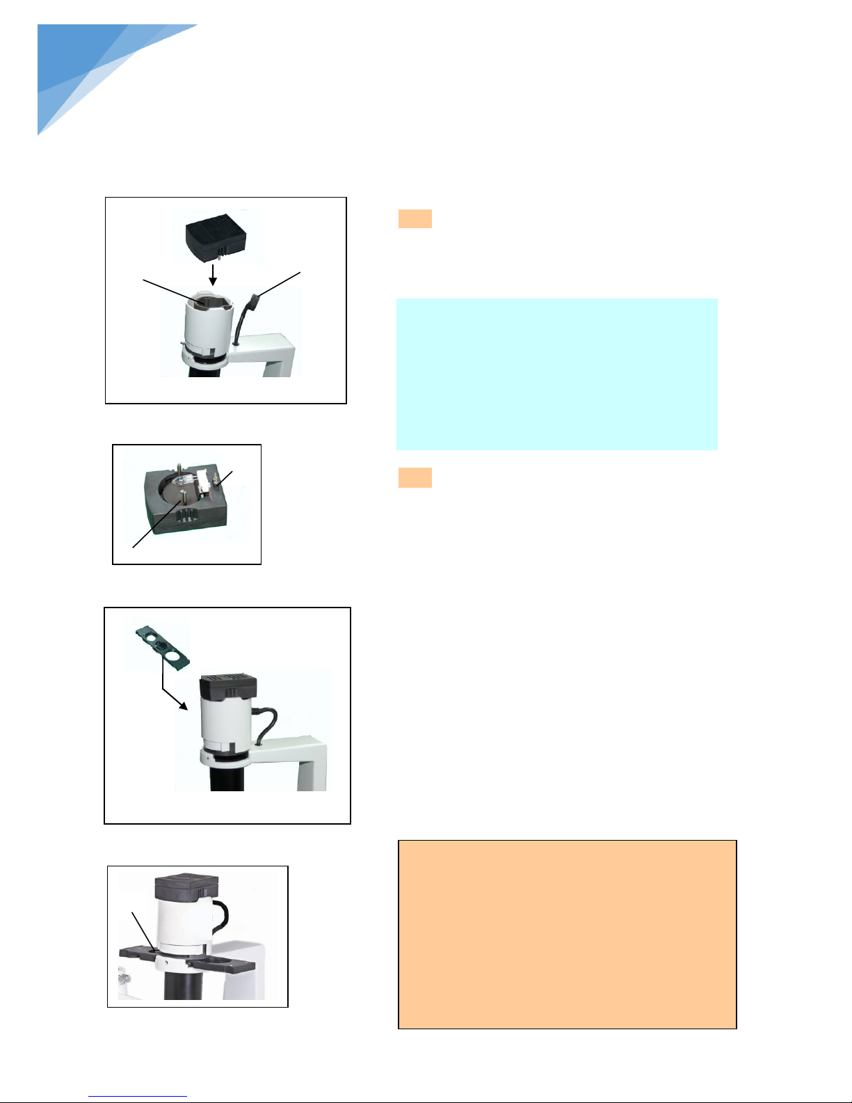
2.2.4 Installing lamp house (fig4, fig5)
Insert the plug A into hole A of power cord, then
insert the plug B into the B hole of the condenser till
there are against. (Fig 6)
2.2.5 Installing phase contrast plate (fig6,
fig7)
1. Keep the slider① face (the surface which had
character) up towards. Every light ring or opening has
its own located position, so you need to move them
until you heard the “clicked” to ensure the ring or the
opening reaches the center of the light path (show as
fig 7).
2. Turn the aperture diaphragm lever ①to adjust
aperture. Turn the diaphragm to a big aperture when
do phase contrast observation.
● The light ring was centered beforehand, so it needn’t
to adjust in the use process. If the ring is not in the
center, you could adjust by the centering bolt.
● The 10X/20X light ring is worked with the 10X, 20X
phase contrast objective, while the opening is
used for bright field.
A
B
A
B
Fig 5
Fig 6
Notices
Requirement:
1. Temperature: 0℃~40℃, max humidity: 85%.
2. High temperature and moisture will damage
instrument and affect performance.
3. Keep the instrument away from the dust
environment, and take the dust cover when no using.
4. Lay the instrument without vibration place.
Fig 7
①
Replace lamp
1. Turn the switch to off position when using or need
replacement. Pull out the lamp house and then the
lamp after it is cool down completely.
2. Insert the new lamp softly to prevent damage.
3. Do not touch the lamp by hands to prevent
reducing lamp expectancy or explode. Clean the
fingerprint by wiping slightly moistened with
ether.
STEINDORFF
Page 9
8
®
Fig 8
②
①
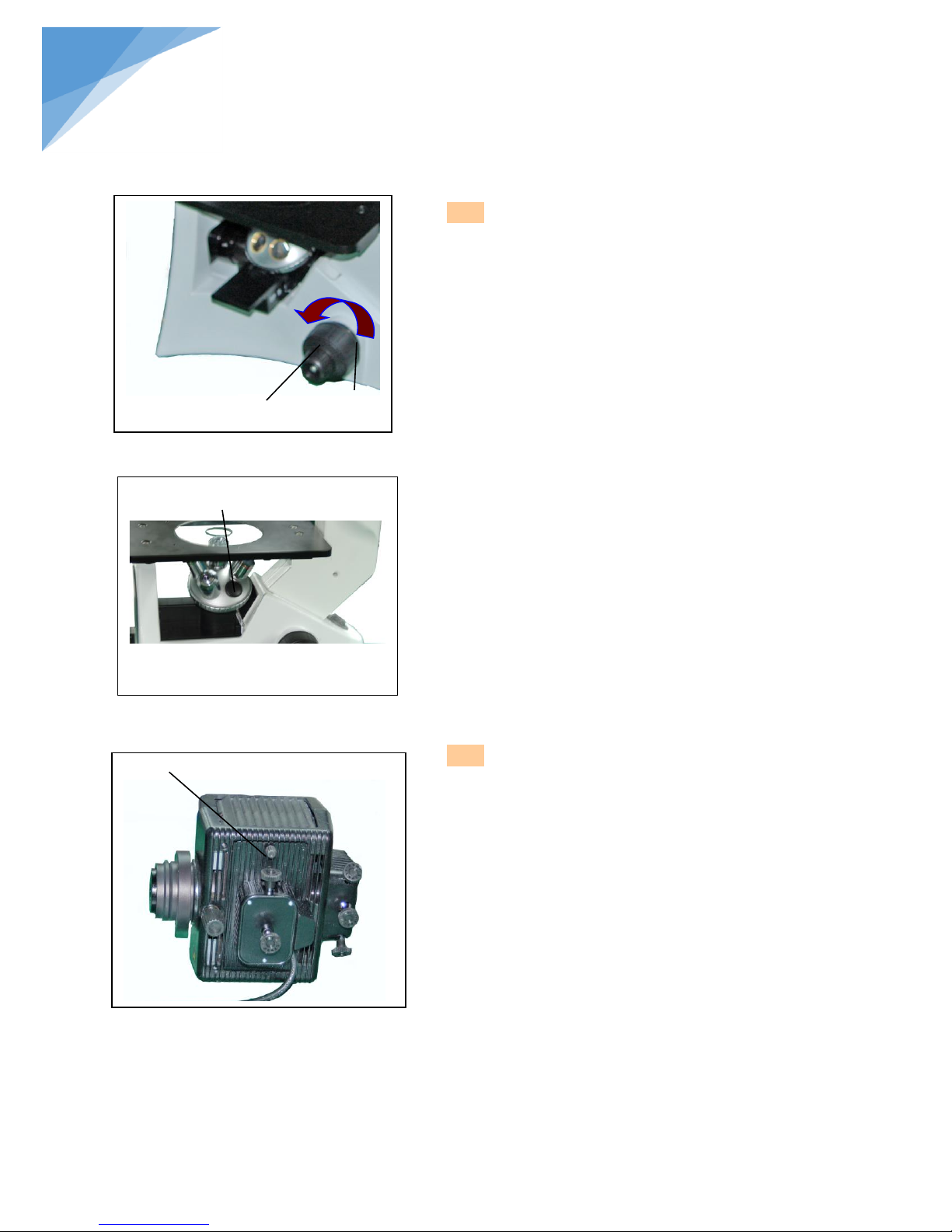
2.2.6 Installing the objective (fig8, fig9)
1. Turning the coarse fusing knob ① like the figure shows till
the nosepiece get to its lowest position.
★For ensuring the safety of the instruction on
transportation, the nosepiece is located in the lowest
position and the tension adjustment collar ② is
adjusted in an appropriate tight tension while leaving
the factory.
2. Screw the lowest magnification objective on to the turret
from the nearside, then turn the turret clockwise, mount
other objectives according the magnification sequence of
low to high.
◎ Mount objective like this way will make the change of
magnification to be very easy in using.
◎ It also can install the objective through the stage opening.
★ Clean the objective regularly, the objective used in the
inversed microscope is very sensitivity about dust.
★ Do cover all the unused holes with turret dust caps ③, to
prevent the dust and contamination entering inside.
★ When operating, use the low magnification objective (4X
or 10X)to search and focus the specimen at first, then
replace the higher magnifications if necessary.
★ When replace the objective, slowly turning the nosepiece
until you hear “clicked”, that means the objective enter
into the right position—center of the light path.
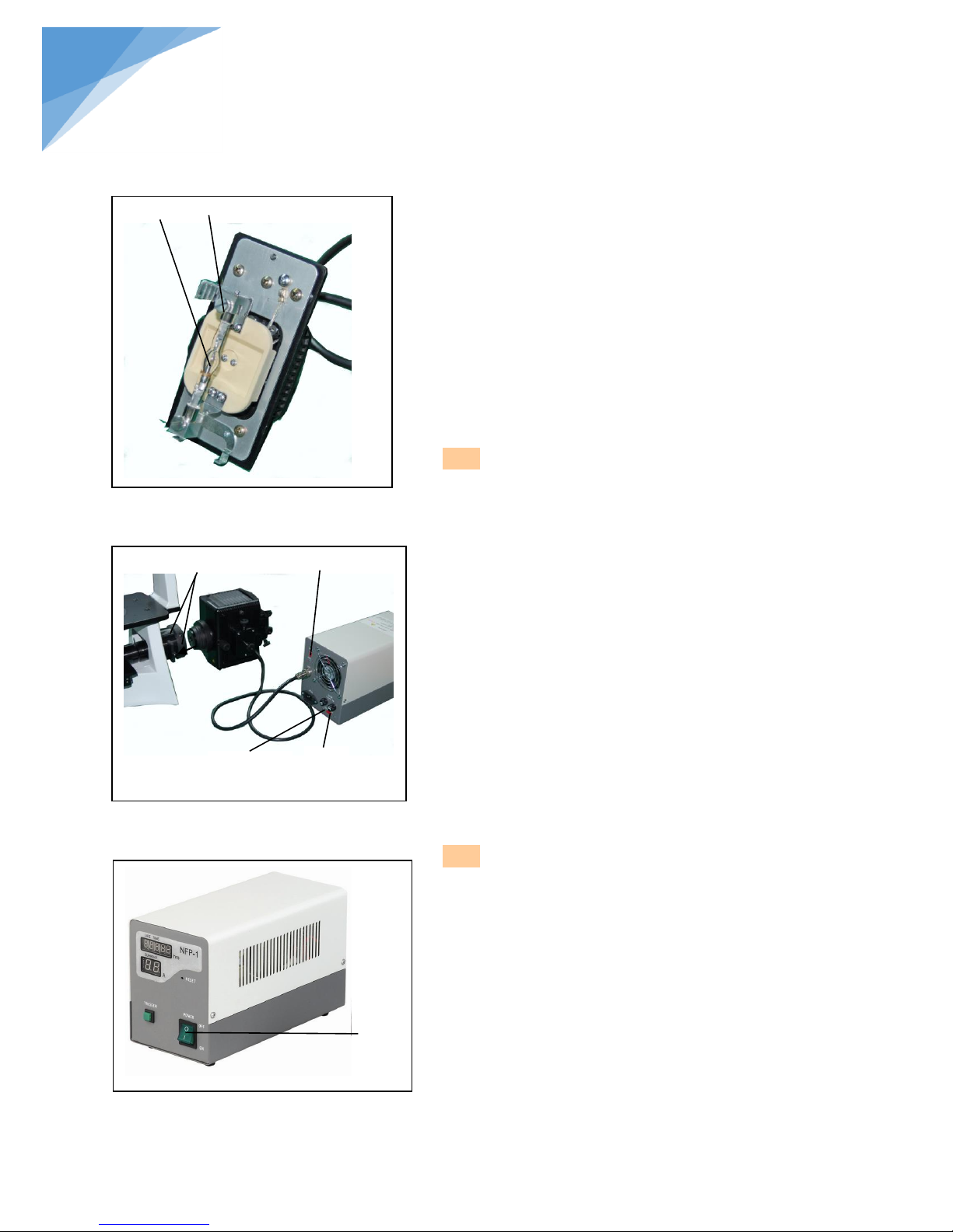
2.2.7 Mounting the Mercury Burner (fig10, fig 11)
1.Loosen the burner socket clamping screw ①, and remove
the burner socket.(fig.1)
2.After removing the foam backstop ②, securely insert the +
pole (the wide head) of the specified mercury burner ③ to
the lower terminal first and then the – pole (the thin head)
to the upper terminal, then tighten the two socket clamping
screws ④.
3.Close the burner socket with burner into the original
position and tighten the socket clamping screw ①.
Fig 10
Fig 9
①
③
STEINDORFF
Page 10
9
®
Fig 13
● Be sure to use a GCQ-100 mercury burner.
● Be sure to mount positive pole(the wide head) before the
other , or the damage to the burner may occur.
● Never subject the burner to excessive force when mounting
the Mercury Burner.
● Be careful and avoid leaving fingerprints or dirt on the
mercury burner. Attached stain may cause distortion in glass
which could result in a ruptured burner. If stained, wipe it a
way gently with clean gauze.
★ To prevent any hazard, always turn the main switch on the
power supply unit to “O” (OFF), unplug the power cord plug
from the mains outlet, and wait for at least 10 minutes before
replacing the burner.
2.2.8 Assembly of the Fluorescent Attachment,
Cable and Cord Connections (fig 12, 13)
1. Mount the lamp housing into the other end of the attachment
and fix it with two screws④.
2.Plug the connector ⑤ from the burner socket securely into
the connector on the power supply unit and make sure the
cord is correctly connected. (Make sure that the main switch
④ of the power supply is set to “O”(OFF)before
connecting cables)
3. Connect the power cord connector ⑥ into connector on the
power supply unit and make sure the cord is correctly
connected.
● Verify that the voltage and the frequency of the AC mains
outlet match the setting of the voltage switch and the
frequency switch on the rear of the power supply units and
improper setting may degrade burner performance, or in the
worst case(although very rare ), cause the burner to explode.
● It is better to use the power cord provided by BestScope and
the same type power cord should be used if you lose or
damage the old one
2.2.9 Fuse Replacement (fig 12, 13)
1 Set the main switch to “O”(OFF)and unplug the power cord
before replacing fuses.
2 Using a flat-blade screwdriver, remove each of the fuses
holders⑦by tuning it counter- clockwise and pulling out.
3 Replace both fuses with new ones.
● Always use the designated fuses (8A). And make sure the
voltage of the fuse match the voltage of the AC mains outlet.
② ③
Fig 12
Fig 11
④
⑥
⑤
Voltage
Frequency
STEINDORFF
Page 11
10
®
Fig 14
①
Fig 15
Fig 16
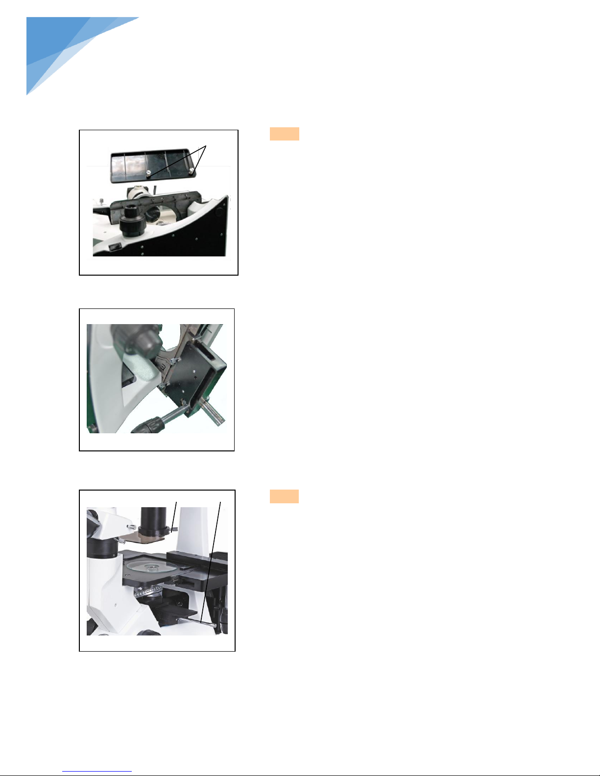
2.2.10
Installing the stage lengthen splint and
the mechanical ruler
(fig 14, 15)
◎ Stage lengthen splint can be installed in either
side of the stage to enlarge the work surface.
But you can’t install the mechanical ruler
together.
◎ Generally, the mechanical ruler will be installed
in the right side for comfortable adjustment.
1. Installing the stage lengthen splint
First, Screw the fixed bolt ① on to the splint,
then mount it on to the stage from right or left
below, screwing down it until it stay hard.
2. Installing the mechanical ruler
Please install the ruler like the way of the stage
splint.
2.2.11 Installing protection barrier, glass
plate, lever (fig 16)
1. Install the protection barrier on the attachment by
tightening the screw ②.
2. Placing the glass plate to the right position.
3. Screw the lever to the inversed components under
the nosepiece.
② ③
STEINDORFF
Page 12
11
®
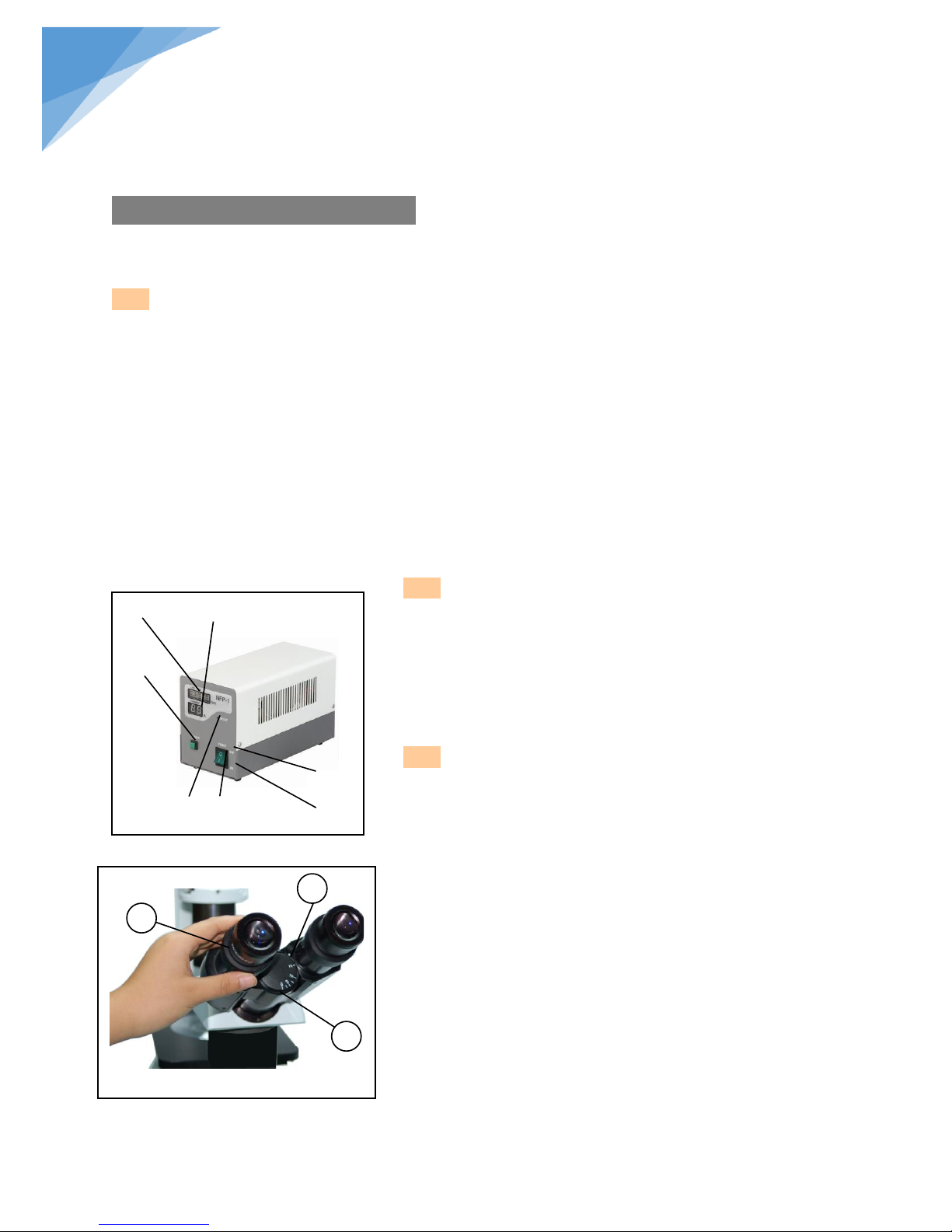
3.1.2 Function of button (fig 1)
① Hour counter
② Ammeter。
③ Excitation button
④ Start reset button
⑤ Voltage switch
3.1.3 Adjusting the diopter (fig 2)
1. Look into the right ocular by your right eye, then
revolving the coarse focus knob to focus on the
specimen.
2. Then use your left eye to look into the left ocular.
If the image is not sharp, just use the diopter
adjustment ring① to adjust please.
★ There are ±5 diopter in the adjustment ring.
The number which the reticle on the eyepiece
holder pointed is your eye’s diopter graduation.
Fig 1
1 2 3
① ②
③
on
off
STEINDORFF
3. Adjustment and operation
3.1 Lamp adjustment for fluorescence observation
3.1.1 Connecting power
Set the main switch of the power supply unit to “I” (ON). It will stabilize in 5 to 10 minutes after ignition.
● Some mercury burners may not ignite the first time the power is turned on due to variance in production,
and the safety mechanism in the starter in such a case. If this occurs, set the main switch to “1” (ON),
then press the starter reset switch on the front panel of the power supply and between 1 to 4 seconds are
required for igniting the burner. Repeat as necessary.
● To avoid shortening the burner life, do not turn the burner off within 15 minutes after ignition.
● The burner cannot be re-ignited for about 10mimutes, that is, until the mercury vapor inside
it has cooled down and condenser to liquid.
● Ensure that the hour counter is reset to “000.00” after replacement of the burner. And you
can insert a thin object such as a mechanical pencil tip into the reset hole on the front panel
of the power supply unit to press the internal switch
④ ⑤
Page 13
12
®
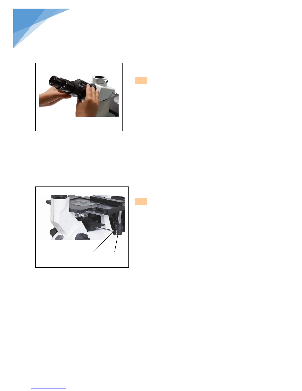
3.1.4 Adjusting the interpupillar distance (fig3)
When observing with two eyes, hold on the left and
right prism holder, turn around the axis, adjusting the
interpupillar distance until the left and right fields of view
coincide completely.
★ The reticle on the interpupillar distance indicator,
pointed by the spot “.” on the eyepiece holder, shows the
scale of the interpupillar distance.
The range of the interpupillar distance: 48~75mm.
3.1.5
Mounting Auxiliary Stage
(fig 4)
1. When using mechanical ruler. Located the specimen
by moving the X,Y knob(120mmх78mm)
2. Use the standard specimen cover (1.2mm) for best
observation.
● Carefully replacing objectives or else the objective will
touch the inserted glass plate when observing the
specimen by short-working distance objective.
Fig 3
Fig 4
STEINDORFF
① ②
Page 14
13
®
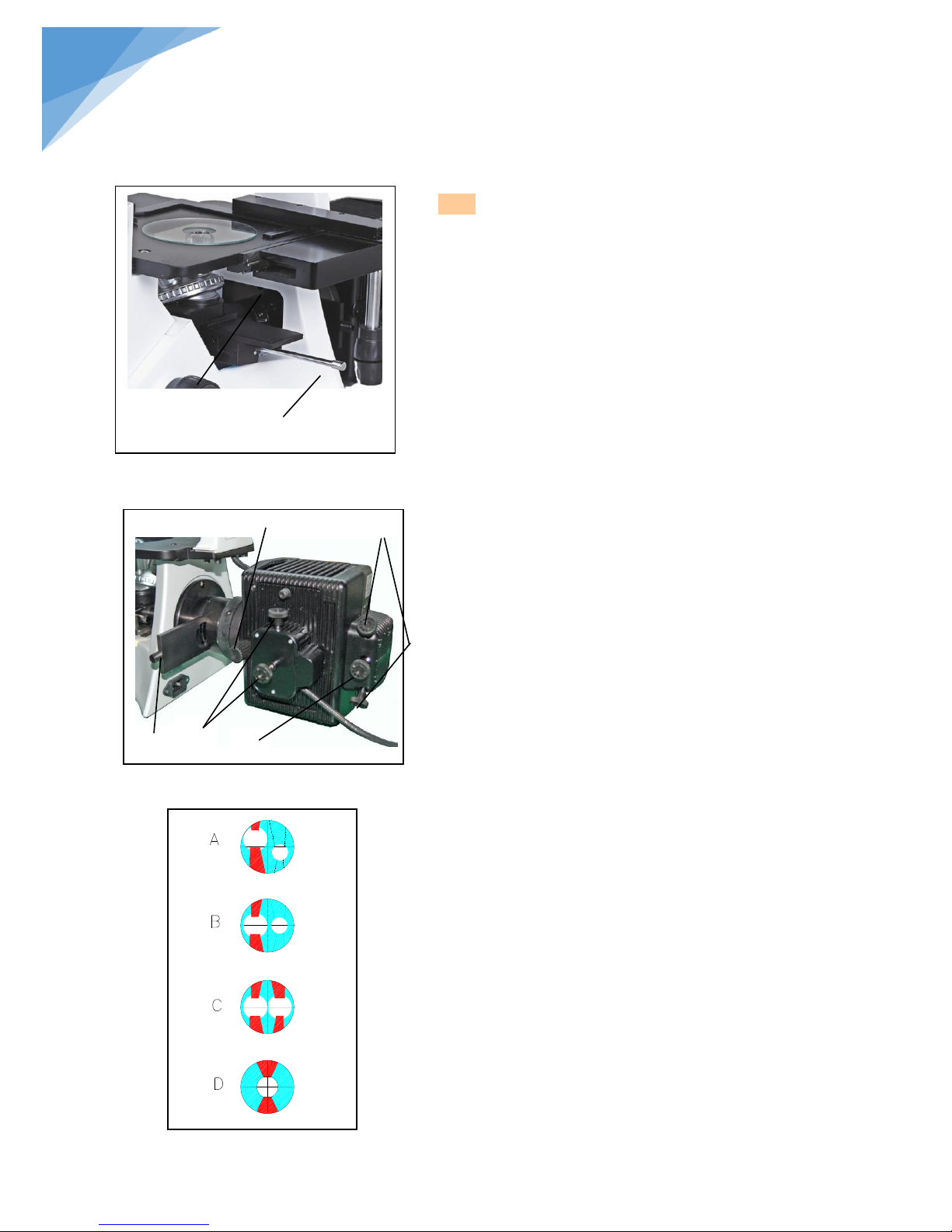
3.1.6 Centering the mercury burner (Fig.5-7)
◎Before proceeding to center the burner, wait for the arc
image to stabilize to protect against glare during arc
image centering, it should be viewed across the
excitation light protective shield.
1. Switch the light shutter ① to“●” position to shut off
the light path.
2. Revolve the filter block turret to engage the green or
blue excitation filter block into the light path. If U/V
excitation filter block used, be sure to use the
protective shield.
3. Revolve the nosepiece to engage 10× objective into
the light path. Place the centering plate on stage,
through transmission observation; adjust the stage
until the cross is in the center of the field of view.
4. Remove the objective from the revolving nosepiece
position and engage this position in the light path.
5. Pull out the field iris diaphragm lever ② to close the
iris diaphragm and push in the aperture iris
diaphragm lever ③ to open the iris diaphragm to the
large limit.
6. Switch the light shutter ① to “O” position to open the
light path.
7. Turn the collector adjusting knob ④ to project the arc
image on the centering plate and sharpen it.(A)
8. Revolve the burner adjusting knob ⑤ to move the arc
image and the mirror reflected arc image in the
symmetrical position.(B)
9. Adjust the mirror focusing knob ⑥ (Fig.6) to
sharpen the mirror reflected arc image. (C)
10.Turn the burner adjusting knob ⑤ to overlap the arc
image with the mirror reflected arc image. (D)
◎ Turn the collector adjusting knob ④ to make the field
of view as bright as regular as possible.
◎ Maintain this condition until the next time the burner is
replaced.
Fig 6
Fig 7
⑤ ⑦
④
⑥
Fig 5
③
STEINDORFF
② ①
Page 15

14
®
STEINDORFF
Note:
● When the hour counter indicates “100.0”, set the main switch to “o” (OFF) for safety, wait for more than 10
minutes, then replace the lamp burner after making sure that the lamp housing has cooled down.
A mercury burner seals high-pressure gas inside. If the burner is used beyond its service life, stress may
accumulate inside the burner, and in the worst (but very rare) case, the burner could explode.
● After replacing with a new burner, reset the hour counter, be sure to press the reset switch until “000.00” is
displayed.
Page 16

15
®
Centering the mirror reflected image (Fig.6)
★ The mirror reflected image has been centered
before leaving the factory. Do not adjust the
knob ⑦ please if not necessary. Only when the
burner has been centered precisely, can the
knob ⑦ be adjusted.
Note: once the knob is adjusted, the reflected
mirror cannot be reconverted to the status when
leaving the factory.
Knob control: (Fig.6):
1. The middle knob ⑥ is the mirror reflected
image focusing knob which can sharpen the
reflected image.
2. The knobs at both sides ⑦ can adjust the
up/down or left/right position of the mirror
reflected image.
3.1.7 Centering the Field Iris Diaphragm (fig 8,
9)
1. Engage the 10×objective in the light path, and
place the specimen on the stage and bring into
approximate focus.
2. Pull the field iris diaphragm lever ② out until the
diaphragm comes into the smallest state.
3. Use the hexangular wrench to adjust the two
field iris diaphragm centering screws alternately
to move the image of the diaphragm to the
center. (Fig.2 show the adjustment of
diaphragm)
4. Push in the field diaphragm lever to open the
diaphragm. As this makes slight deviation
noticeable, adjust the centering precisely.
5. Enlarge the diaphragm until it just circumscribes
the field of view.
Fig 8
②
Adjusting the field iris diaphragm
The field diaphragm adjusts the diameter of the illuminating
beam to obtain good image contrast.
Keeping the field diaphragm stopped down to the smallest
required area for each observation makes it possible to prevent
color fading of areas outside the observation target region.
According to the objective in use, adjust the diaphragm image
using the field diaphragm lever so that the field of view is
circumscribed by the field diaphragm to exclude stray light.
Fig 9
c
b
a
STEINDORFF
① ③ ④
Page 17
16
®
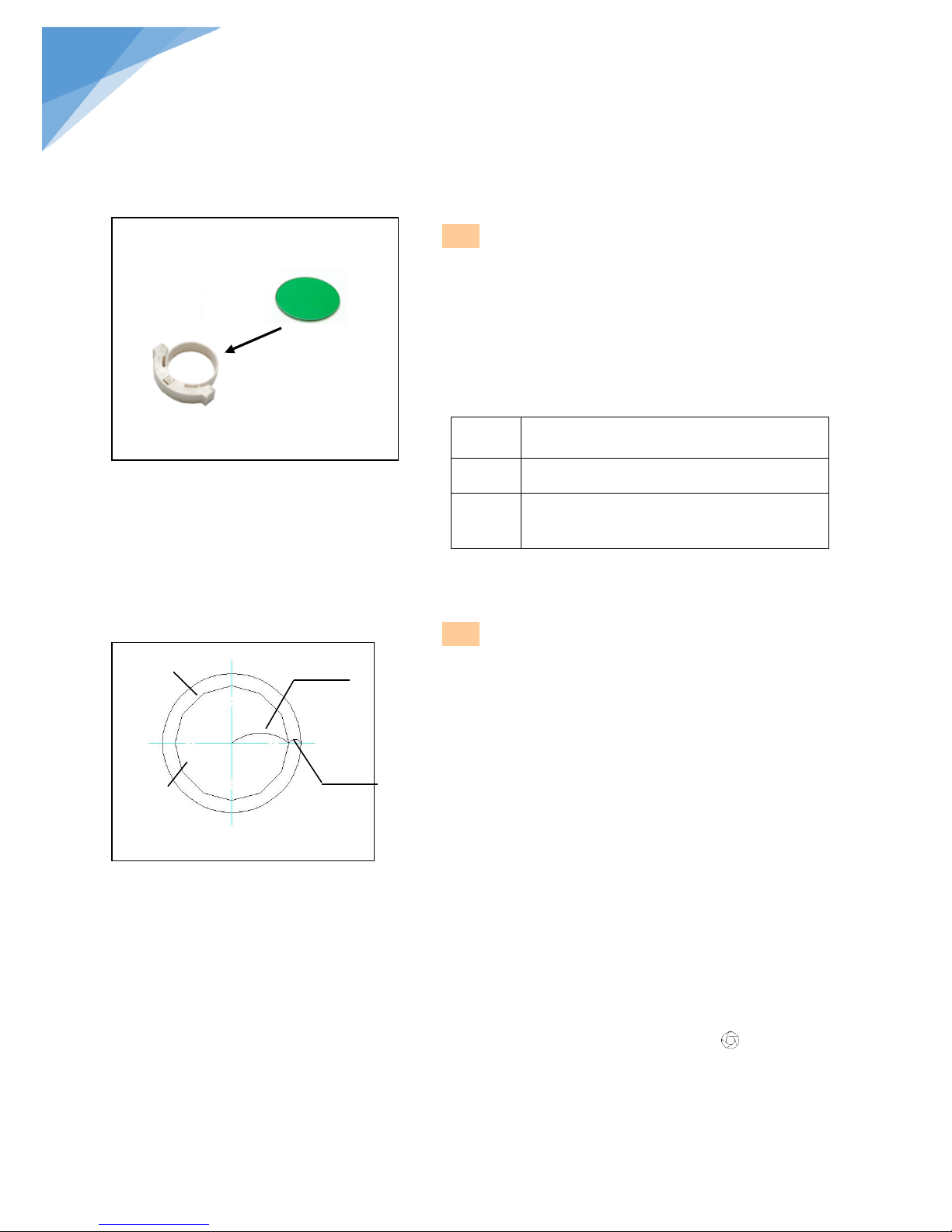
3.1.8 Using color filters(fig 10)
◎ Selecting the appropriate color filters according your need,
it became more effective to observe or photography the
specimen. Especially, we suggest using the LBD color
filter, which can compensate more neutral colors.
◎ You could pile up a group of color filters to the filter
holder, if you ensure they are level and the whole
thickness is less than 11mm.
Color
filter
Meaning
IF550
Single contrast color filter (green)
(used for the phase contrast microscopy)
LBD
Color temperature transit color filter(blue)
(used for bright field observation and
microphotography)
3.1.9 Using the aperture diaphragm(fig 11)
◎ When in the bright field observation, the aperture
diaphragm control the numerical aperture of the
illumination system. Only when the numerical aperture
of the objective and the illumination system being
matching, you can obtain the higher image resolution and
contrast, and the increased depth of field, too.
Fig 10
Fig 11
①
②
70-80%
30-20%
STEINDORFF
● To recognize the aperture diaphragm, you could remove the eyepiece if necessary (You also could insert in the
center telescope), then looked into the viewing tube, you might see a field of view like the figure shown. The
proportion could be changed by dialing the aperture adjustment lever according your need. (①is the image of
the aperture diaphragm, ② is the edge of the objective)
● Generally, when observing the chromatic specimen, you need to set the size of the condenser aperture
diaphragm at 70%~80% of the numerical aperture which marked in the objective, but if observing the bacterium
specimen which not colored, you could turn the aperture diaphragm lever at the direction of “ ”(clockwise)
Page 18
17
®
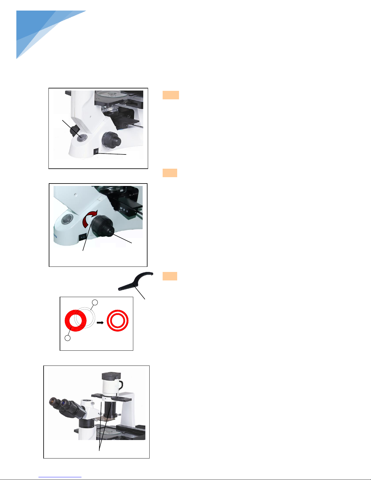
3.2.1
Turn power, adjusting brightness (fig 12)
Connect the power, turn on the main switch ① (shown
on the fig.12) which on the bottom side of the base to
“-” (on). Turning the brightness adjustment knob
clockwise ②, the voltage raise, and the brightness
strengthen; whereas turning at the contra direction, the
voltage decline, and the brightness weaken.
◎Using the lamp in a low voltage condition, will
prolong the service life.
3.2.2 Adjusting the Tension Adjustment Collar
(fig13)
The tension of the coarse focusing
knob② has already been adjusted properly
before leaving factory.
◎How to adjust tension of the coarse focusing knob?
Turn the tension adjustment collar ①. While revolving
at the direction of the arrow in the figure, the tension of
the coarse focusing knob ② is increasing, and if at the
contra direction, the tension will decline.
3.2.3 The centering ring (fig 14, 15)
★ Usually you do not need the operation of centering.
If necessary, please accord to the following steps:
1. Place the specimen on the stage and focus it.
2. Take out the eyepiece, replace it with the CT (the
centering telescope), and inserted it into the
viewing tube without diopter adjustment.
3. Make sure the matched phase contrast objective and
light ring (in the phase contrast slider) have been
in the center of the light path.
Fig 12
②
①
Fig 13
③
②
①
Fig 14
2
1
③
Fig 15
knob
STEINDORFF
3.2 Reflected observing illumination adjustment
knob
Page 19

18
®
STEINDORFF
4. Using the CT to l: the light ring’s image① and the phase contrast ring’s image②, if the light ring’s image is
not sharp, please shifting the CT’s ocular until you can see a clear image of the light ring②.
5. Adjusting the bolts of the two centering holes③ in the phase contrast slider by the screwdriver ③until the
light ring center and the phase contrast center are coincided.
6. The 10X and the 20X phase contrast objective use the same light ring on the phase contrast slider. So you
need to check the coincidence of the light ring center and the phase contrast center when changing the
objective. If having departure, you ought to center again.
★ If the light ring is centering incorrectly, you will fail to obtain the best viewing effect of the microscopy.
★ After removing or replacing a thick specimen, the light ring and the phase contrast ring are likely to
deviate each other, which will result in a decline of the image contrast. So if happened, please repeat
the steps as above.
★ If the container or the cover flip which used to place the specimen is not flat, it maybe need to repeat
the centering steps for obtaining a more contrast effect. Please center the light ring by the phase
contrast objective, according to the sequence of low to high magnification.
Page 20
19
®
Fig.16
STEINDORFF
3.3 Digital LCD biological microscope operation interface
3.3.1 Power on
Before power on, please take out the SD card from the card reader firstly. Insert SD card into SD slot behind the
microscope head completely until it is locked. Push softly the inserted SD card, it will eject out, then take it out
(When the card is under reading or writing, do not pull it out. Better power off first before pulling out the SD
card).
Connect the DC plug of the power adapter to the “DC” jack on the microscope head. Press the power switch
on the control board, “WELCOME” should appear on the LCD screen. After 3 seconds, the microscope
system will be in the preview in the real time automatically when you can snap.
Adjust microscope’s definition: according to its imaging focal length, make both images sharp from eyepiece
and LCD display screen, and then the adjustment is done.
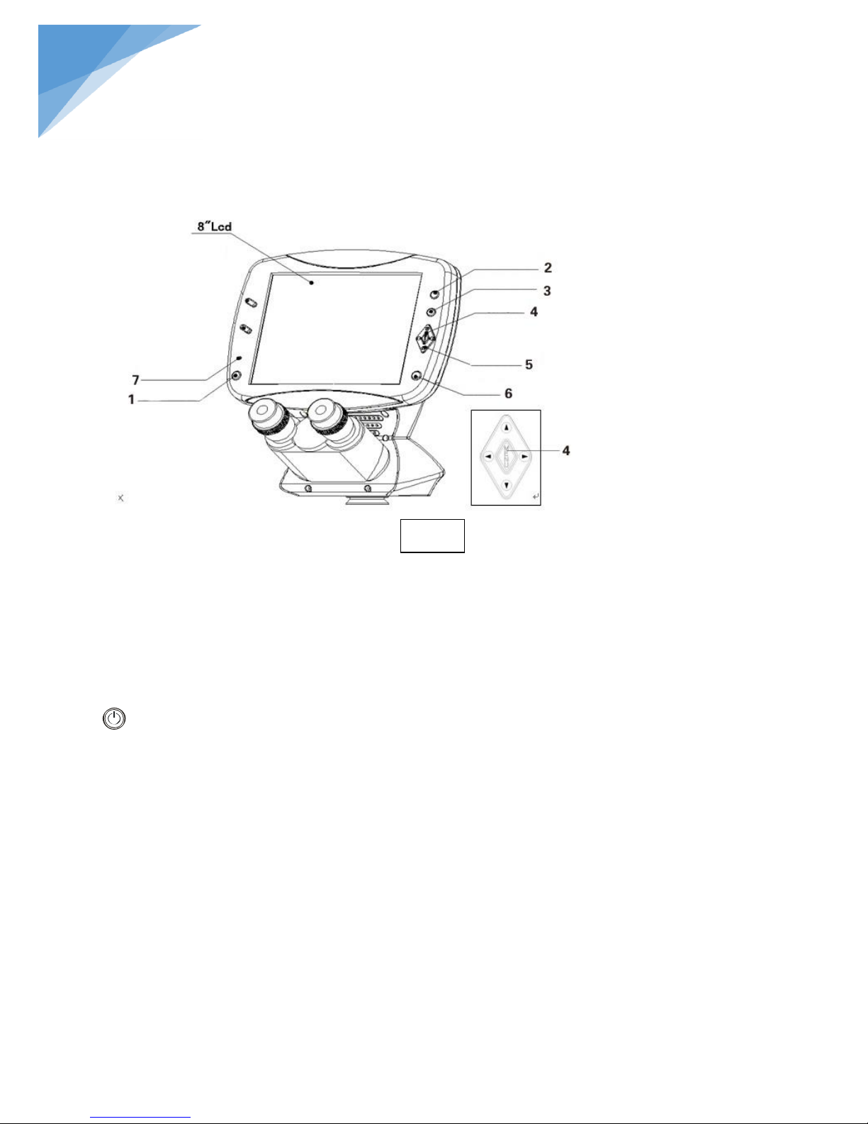
3.3.2 Operation buttons and functions
1. Power button:apply power,make microscope working;
2. Mode switching button:snap/video/playback;
3. AV output switching: LCD screen display/AV output switching button
4. Main menu button:menu function control and confirm
5. Menu direction button: menu function select by pressing up/down/left/right buttons
6. Snap button:snap and video function
7. Power indicator
Page 21

20
®
Fig17-01
Shown on the upper right corner is the Nos of photos that can be taken or the video recording time(“0000”
means in the current setup mode, it still can shoot 0000pcs photos). (“00:00:00” means in current
setup mode it still can record 00min 00sec).
On the upper left corner, indicates photo mode, indicates video mode.
Pic17-01, Shown on the top middle “5M” is the resolution of photos taken in Pixels.(“5M”indicating the
pixels for photo taken at the present setup mode as 2560x1920. (“VGA” indicating the pixels for video
taken at the present setup mode as 640X480.
“SD” show on the lower left corner means that SD card inserted is inserted in the LCD microscope head.
“CARD FULL” indicates that the memory of the SD card is full.
Fig.17-02
Fig17-03
STEINDORFF
Adjustment & Operation
3.3.3 Screen display data
Press button to select snap, video or playback.
1. Fig.17-01. Once the power on, the model is snap (photo) model. Press button,the system will store
the photo automatically.
2. Fig.17-02. Press the button after power on, the model is video model. Press button, the
system will start to take video recording, press button again, video recording is over. When the SD
card is full, the system will show “SD full”.
3. Fig.17-03. Press the button 2times after power on, the model is playback model.
Page 22
21
®
On the snap model, press menu button to enter menu interface. Use up & down key to
select a setting from the above 3 items.
A:Image size / B:Image quality / C:Setting data
Fig.17-05
Fig.17-04
STEINDORFF
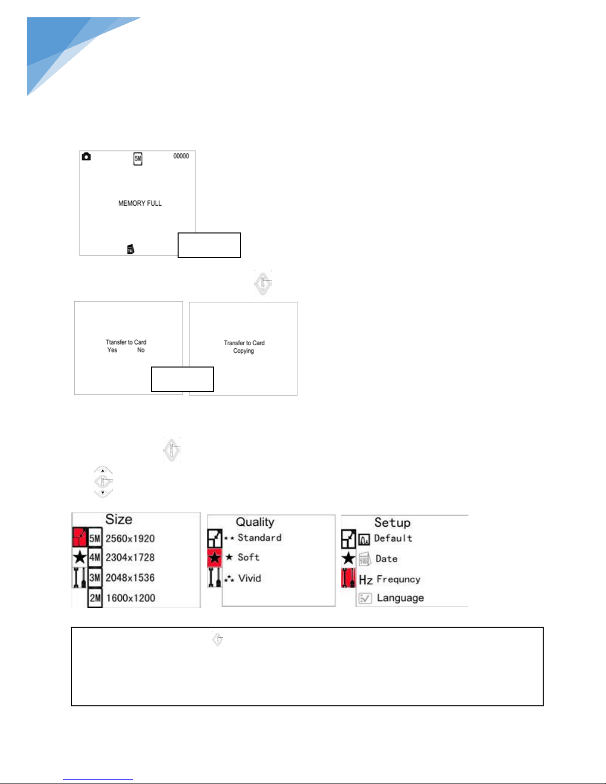
4. Fig17-04, “MEMORU FULL” indicates that the memory of LCD microscope head is full.
Due to the built-in memory of the LCD microscope head is very small, it can be stored on piece photo .
Please insert SD card firstly before your snap.
5. Fig17-05 ,When transfer the photo from the LCD microscope head to SD card ,press the left key to select
“Yes” and confirm by the menu button .
If you press “No” by menu button, the photo remains stored on the LCD Microscope head itself.
3.3.4 Function menu select
With the help of the function, one is able to carry out the setting of the whole system. The up and down
key allows you to choose the following functions:
Page 23
22
®
Fig.18-01
Select photo and video resolution.
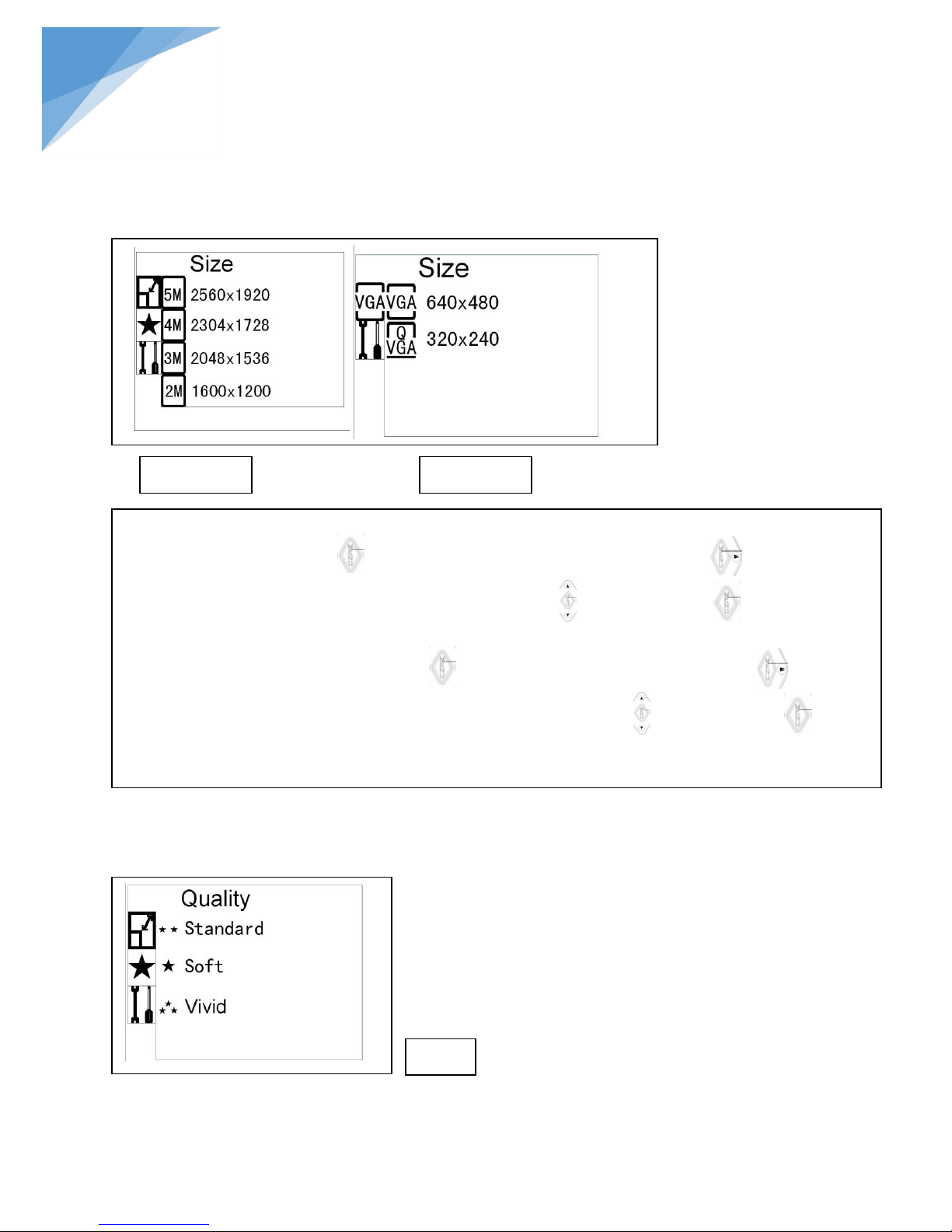
Fig.18-01.On snap model, press button as shown the “Size” ,then press the right key to select the pixels
for photo taken base on 5M/4M/3M/2M use by up & down keys . Press menu button again to save your
selection. Exit from the setting up after confirmation, the model comes back to the snap model.
Fig.18-02.On video model, press menu button as shown the “Size” ,then press the right key to select the
pixels for video taken base on 640X480 or 320X240 use by up & down keys . Press menu button again to
save your selection. Exit from the setting up after confirmation, the model comes back to the video model.
Fig.19
Fig.18-02
STEINDORFF
A、Image size
B、Image quality
Page 24
23
®
Fig.19. Quality: image quality
On snap model, press button as shown the “Size”, then press the down key to enter the “Quality”.
Then press the right key to select as Standard/Soft/Vivid by pressing up & down keys . Press menu button
again to save your selection.
Exit from the setting up after confirmation, the model comes back to the snap model.
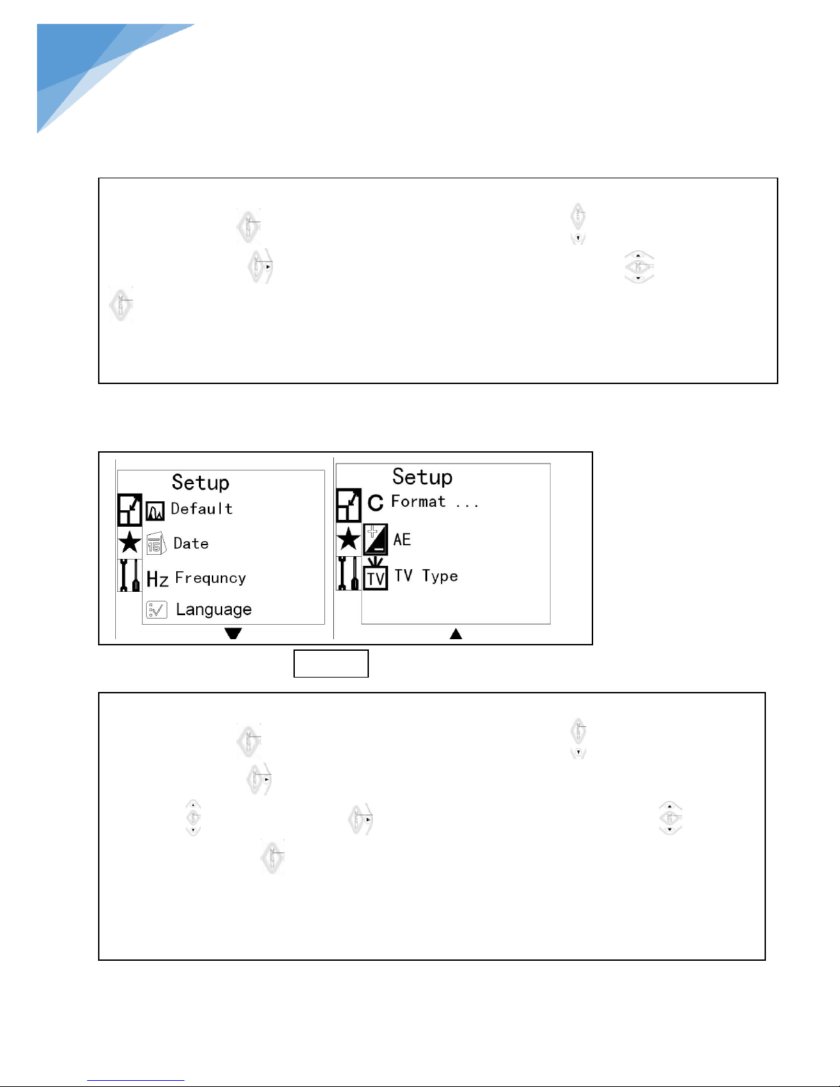
Fig.20.Setup: Setting up each item.
On snap model, press button as shown the “Size”, then press the down key to enter the “Setup”.
Then press the right key to select as Default /Date/Frequency/Language/Format/ AE/TV Type by pressing up
& down keys . Then press the right key to enter the setting items by use up & down keys to select the
option. Press menu button again to save your selection. Exit from the setting up after confirmation, the model
comes back to the snap model.
On video model, the operation is same.
Fig.20
STEINDORFF
C、Setting date
Page 25
24
®
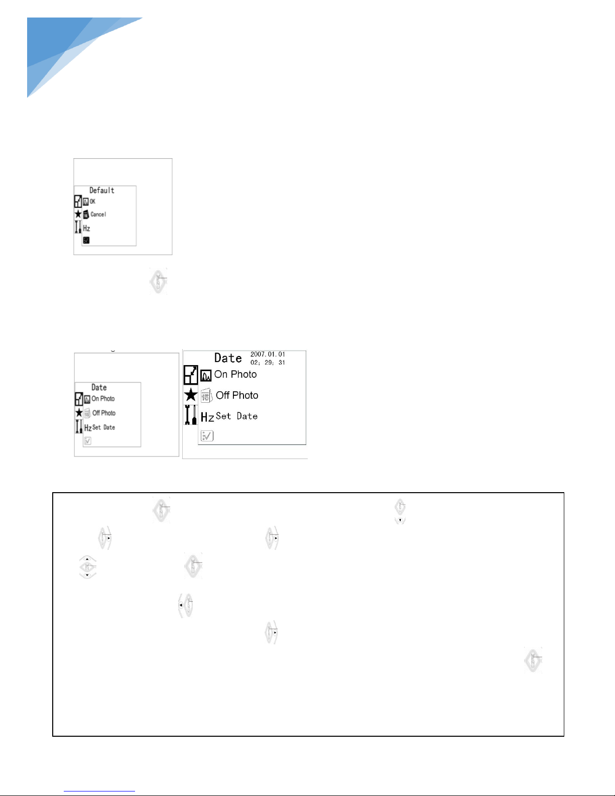
On snap model, press button as shown the “Size” ,then press the down key to enter the “Setup”. Then press the
right key to select “Date”, press the right key once again to select On Photo/Off Photo/Set Date by up & down
keys . Press menu button to confirm selecting “On Photo”, the present date and time will be indicated on the
lower right corner of the photo. Select “Off Photo” to turn off the time recording on the photo taken.
When you press the left key , it will be return the previous set position.
When you select “Set Date”, press the right key to select year, month, day, hour, minute and second on the upper
right corner. The up/down/right/left keys can be used to set up the current date and time. Press menu button to
save your setting. Exit from the setting up after confirmation, the model comes back to the snap model.
To select “On Photo” or “Off Photo”, it will decide whether the date and time information is stored with photos in SD
card or not. This camera shows time as Year/ Moth/ Date and 24 hours.
On video model, the operation is same.
STEINDORFF
3. 3.5 Setting items details
A. Default
This camera will save all of functions after you set up, even power off; the setting changes will be stored after
press menu button . If you want come back to the original settings, please find “Default” in the menu, select
“ok” and confirm. When you select “Cancel” and press menu button, the model comes back to the snap model.
B. Date
Date and time information can be stored together with photo taken in SD card. File names also contain date and
time information. Before using this camera, please set the date and time properly. Setting method is the following:
Page 26
25
®
STEINDORFF
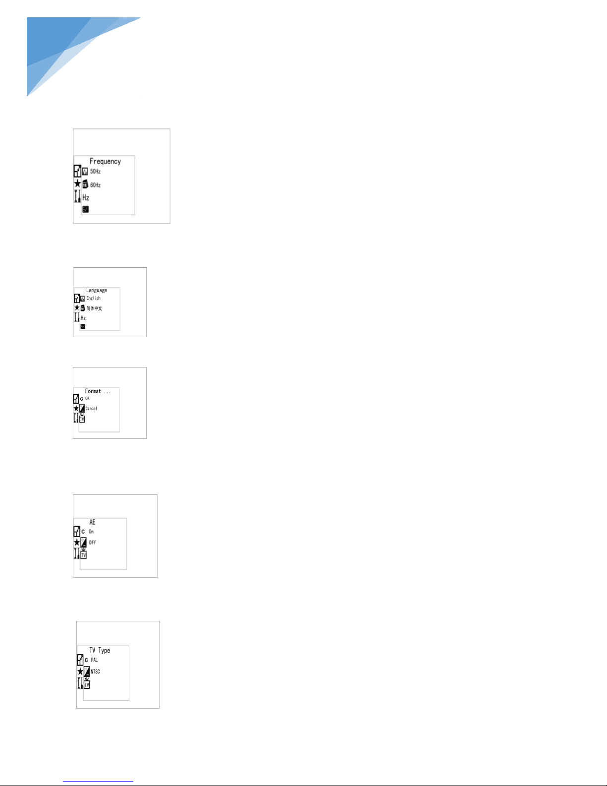
C.Hz: Frequency
Pressing up/down keys to select 50Hz/60Hz according to the local power frequency.
D. Language
Pressing up/down keys to select English
E. Format
Select “OK” can format all the SD card inserted; (Attention:Even the protected content will be deleted
when formatting, cannot be resumed again.) Select “Cancel” and press menu button, the model comes back to
the snap model.
F.AE
”On” means auto exposure,The programmer will adjust exposure value automatically according to the
lightness of the shooting object. Select “off”, the exposure will depend on environment brightness.
G. TV Type
Page 27
26
®
A. Delete Photo or video
B. Lock Photo or video
C. Observation of rotating Photo
STEINDORFF
Pressing up/down keys to select NTSC/PAL for the video output according to local video signal.
This function need be set up when this camera is connected to TV in other countries. Make sure the correct
video system type was selected before connecting AV cables. Otherwise the recorded video cannot be showed
on TV.
TV system of the main countries and areas:
NTSC: North America,Japan,Taiwan,South Korea
PAL: Europe,China
On video model, the operation is as same as above.
3.3.6 Shooting and edit
Press button 2time to select playback model.
Press up & down keys to browse every photo and video which is taken and stored in the SD card.
Press left key, the screen will display multi photos and videos. Index display helps to find target photo or
video quickly in many pictures and videos.
Select some photo, then press menu button to display the single photo on LCD screen.
Select some video, then press menu button to play the video recording on LCD screen.
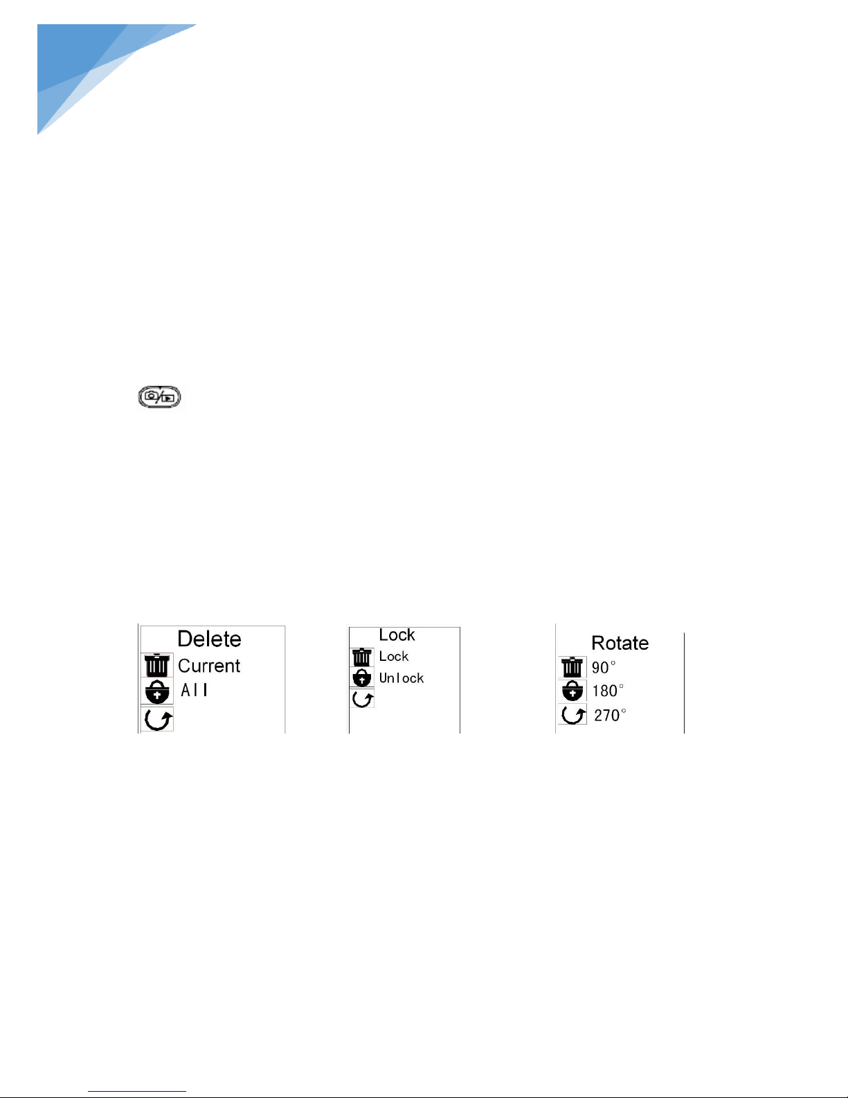
On playback mode, press menu button to find “Delete” function ,press right key and select “Current” or “All”
use up& down keys to delete single photo(video) or all photos(video).
Press menu button to find “Lock “function by down key. Then press the right key to select “lock” or “unlock”
use by up & down keys. (Locked photos and videos cannot be deleted, but can be formatted).
”Rotate” function can rotate photos(90,180,270)degrees。
On playback mode, select the three functions on the menu as below by pressing up/down keys:
3. 3.7 USB data communication
USB mode
You can use USB cable to connect to computer, Install the driver on PC as we attached, the photos stored in
SD card will be sent to computer easily via USB. You also can take photos and videos on PC.
A. Mass Storage mode(MSDC)
To read the stored information in LCD microscope head through computer。
Connect to PC with USB cable, power on, press the menu button on MSDC mode (Fig.16-02). There is a
removable disc icon in PC, click DCIM/100MEDIA/,can down load pictures;Also can be used a U driver
to store any format files.
Page 28
27
®
Fig21-01
Fig.21-02
Fig.21-03
STEINDORFF
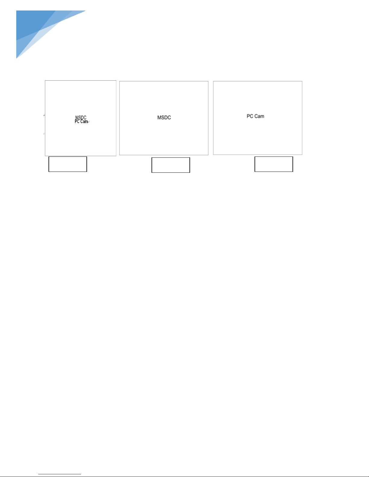
B. PC mode(PC CAM)
Connect to PC with USB cable, power on, press up& down keys to select” PC CAM “mode, and confirm by the
menu button (Fig.21-03). Meantime the screen become blue.
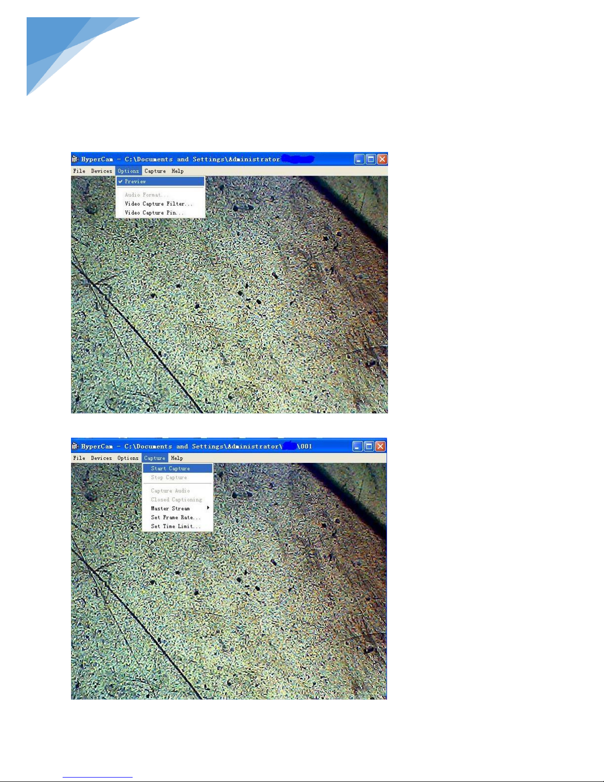
Now we can open the installed driver and find “PCCam” on the desktop of PC.
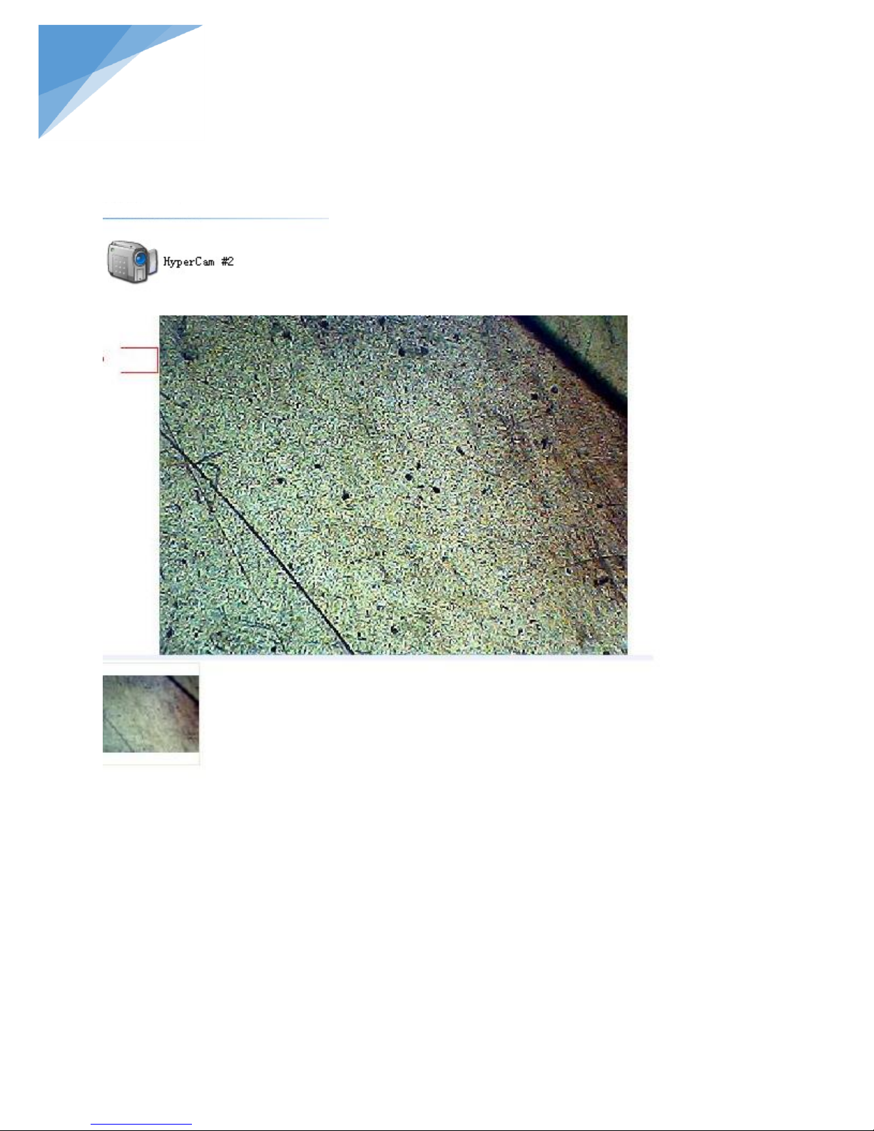
Choose option to preview the real time imaging or take photo and video through PC. This function requires an
observation software installed.
Page 29
28
®
STEINDORFF
Preview:
Take video
Page 30
29
®
STEINDORFF
Take photo
3. 3.8 Image definition
Base on the pixel limitation (800*600) of microscope LCD screen, so through AV outputting, TV can show a
sharper picture than on microscope screen. Also, the microscope shoots pictures as 2560*1920 pixels, when
playback on TV or PC, picture is sharper and clearer than the image on real time preview model.
Page 31
30
®
Fig.22
Fig.24
Fig.23
STEINDORFF
3.3.9 Cross Hair& Reticle Control
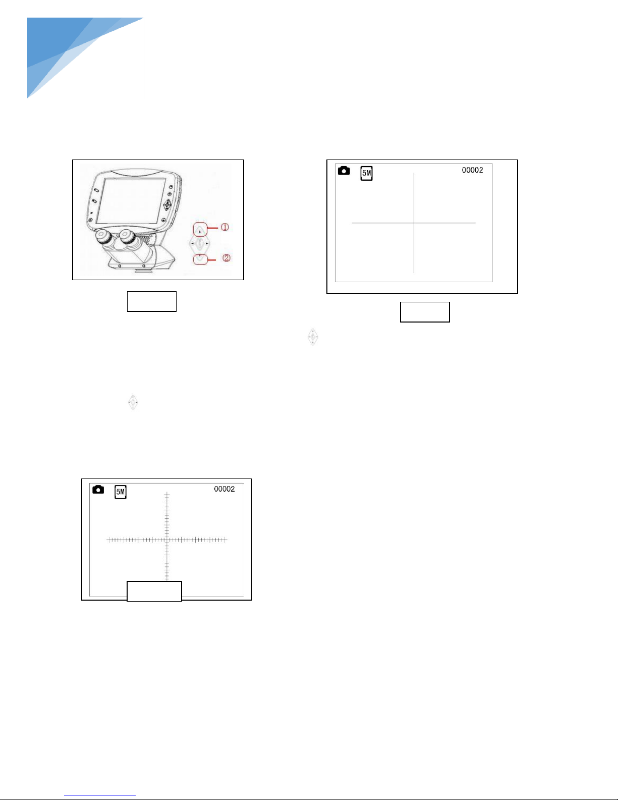
On snap model, you can press the up key of the menu button (Fig.22 ①) to select self-definition graphics,
including the crossing line and reticle with crossing line. The graphics is display on the LCD screen to carrying
out simple locating and measurement
Press the up key one time, the cross hair will be showed on the LCD screen (Fig.23).Then press the down key
of the menu button (Fig.22.②),there are 5colors available(green, blue, black, white and red).It used to
select among colors of the self-definition graphics, facilitating the clear indication under different color
materials
If you press up key (Fig.22①) two time, the reticle will be showed
on the LCD screen (Fig.24)
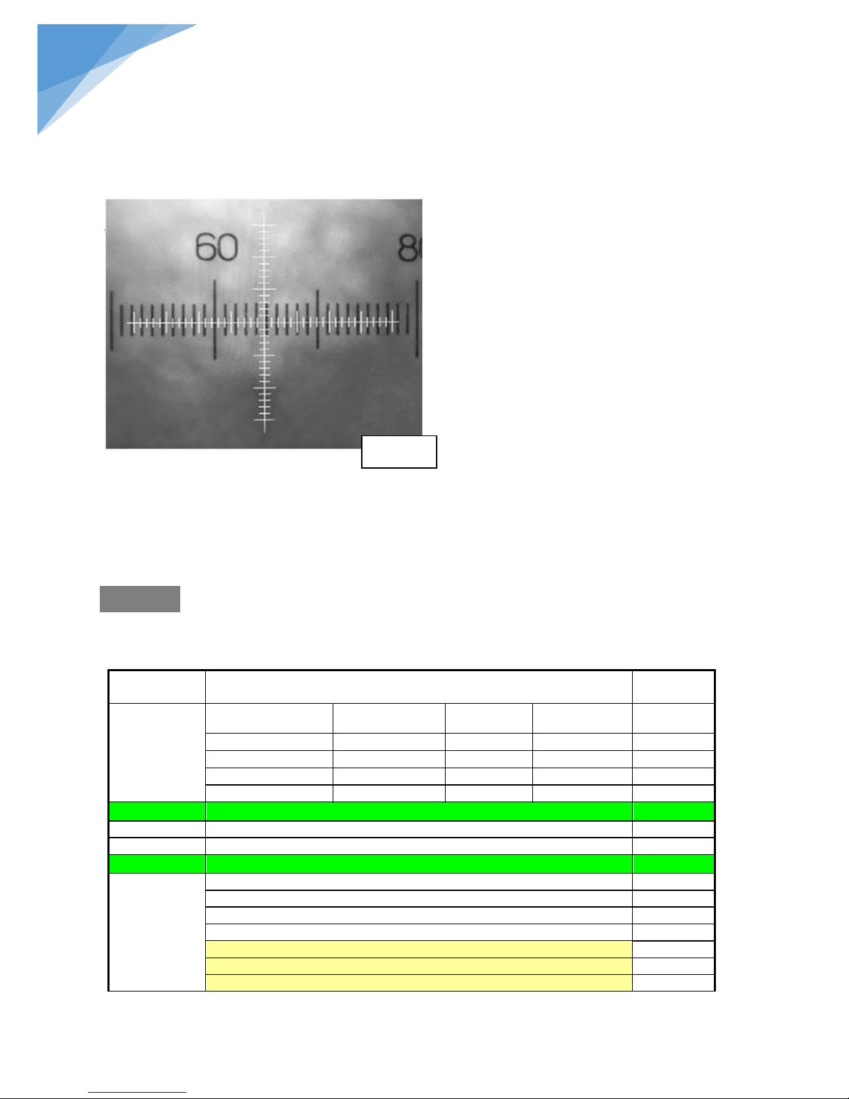
Numerical value of graduation, Please refer to the below:
A graduation equals 0.05mm under 4X objective
A graduation equals 0.02mm under 10X objective
A graduation equals 0.005mm under 40X objective
A graduation equals 0.002mm under 100X
objective
Then, press the up key (Fig.22 ①) once again on the Fig.24, the cross hair will disappear.
Page 32
31
®
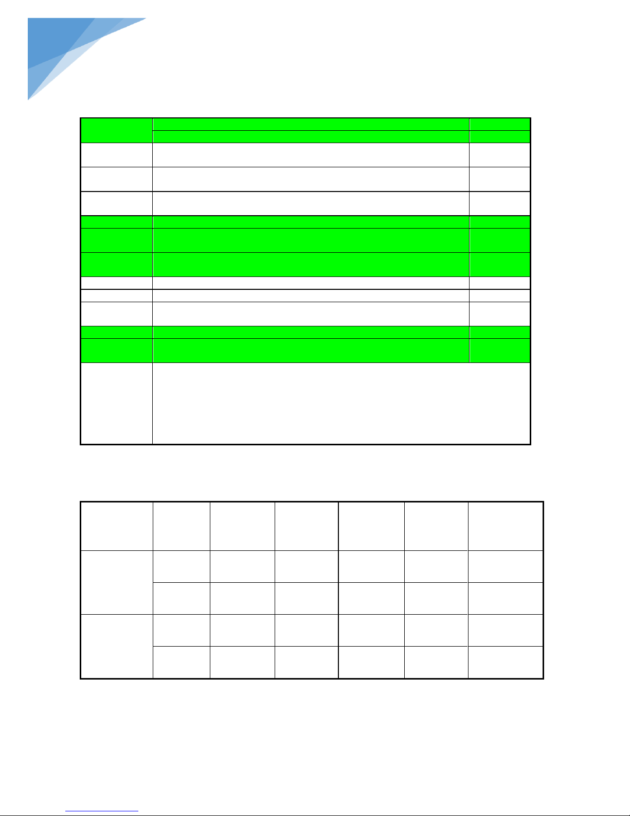
Optical system
Infinite optical system
NYMCS-
1701
Reflected light
source
Excitation units
excitation
Dichroic
mirror
Barrier filter
Blue Excitation
BP460~490
DM500
BA520
●
Green Excitation
BP510~550
DM570
BA590
●
Ultraviolet Excitation
BP330~385
DM400
BA420
○
Violet Excitation
BP400~410
DM455
BA455
○
Viewing Tube
Trinocular head ,30°incline;interpupilary range 48-75mm
●
Eyepiece
High point ,extra-wide field eyepieceEW10×/22
●
Centering
Centering (φ30mm)
○
Nosepiece
Backward Quintuple Nosepiece
●
Objectives
In finite plan long working distance objective 4×
●
In finite plan long working distance objective 10×
○
In finite plan long working distance objective 20×
○
In finite plan long working distance objective 40×
●
In finite plan phase contrast objective PH10×
●
In finite plan phase contrast objective PH20×
●
In finite plan phase contrast objective PH40×
○
Fig.25
STEINDORFF
3.3.10 How to use the reticle to measure?
Example
Selected the standard graduation of 0.05mm under a given power and move the micro-ruler when clearly focused
so that the coordinate corresponds with the micro-ruler. The standard ruler of every 12 graduations correspond
to 19 graduations of the coordinate ruler, then each graduations of the coordinate ruler is about 0.03mm.In this
case, user can carry out the measurement for the object observed under microscope according the distance of
coordinate ruler(requiring re-calibration of the separation of coordinate ruler each time for a changed power).
4. Outfit
4.1 Specification
Page 33
32
®
Phase contrast
slider
10×-20×, 40×phase annulus plate
●
10×-20×, 40×phase annulus plate
○
Mechanical
stage
Stage: 160×250mm, inserted plate, Stage strengthen plate:70×180mm.
●
Mechanical
ruler
Movement: 120×78mm
●
Reflected
illumination
6V30W Halogen lamp, brightness adjustable
●
Illumination
100WHBO ultra Hi-voltage spherical mercury lamp
●
Protection
barrier
Barrier to resist the ultraviolet light
●
Photography
Attachment
●
Video ○
Power
Power supplier NFP-1, 220V/110V interchangeable ,digital display
●
Condenser
Ultra-long working distance condenser, aperture number 0.3, working distance
72mm
●
Filter
45mm blue, green and ground glass
●
Focusing
Coaxial coarse and fine adjustment, vertical objectives movement. Coarse stroke:
37.7mm per rotation. Fine stroke :0.2mm per rotation
Operation
condition
Use indoor
Altitude: Maximum 2000 m
Temperature: 5℃~40℃(41°F~109°F)
Maximum Relative Humidity: 80% at 31℃ (88°F), then Fall Linear.
70% at 34℃ (93°F), 60% at 37℃ (104°F), 50% at 40℃ (104°F).
Pollution Degree:2 (refer to IEC60664)
TYPE
MAGNIFIC
ATION
NUMERICA
L
APERTURE
(N.A)
WORKING
DISTANCE
(mm)
CONJUGATE
DISTANCE
(mm)
FOCUS
DISTANCE
(mm)
COVER SLIP
THICKNESS
Infinite Long
Working
Distance Plan
Achromatic
Objective
4X
0.1
25.2 ∞ 45
─
40X
0.6
3.2 ∞ 45
1.2mm
Infinite Long
Working
Distance Plan
Phase Contrast
Objective
10X
0.25
11 ∞ 45
0.17
20X
0.4 6 ∞
45
0.17
STEINDORFF
Note:●standard outfit ,○ optional
4.2 Objective Specifications
Page 34
33
®
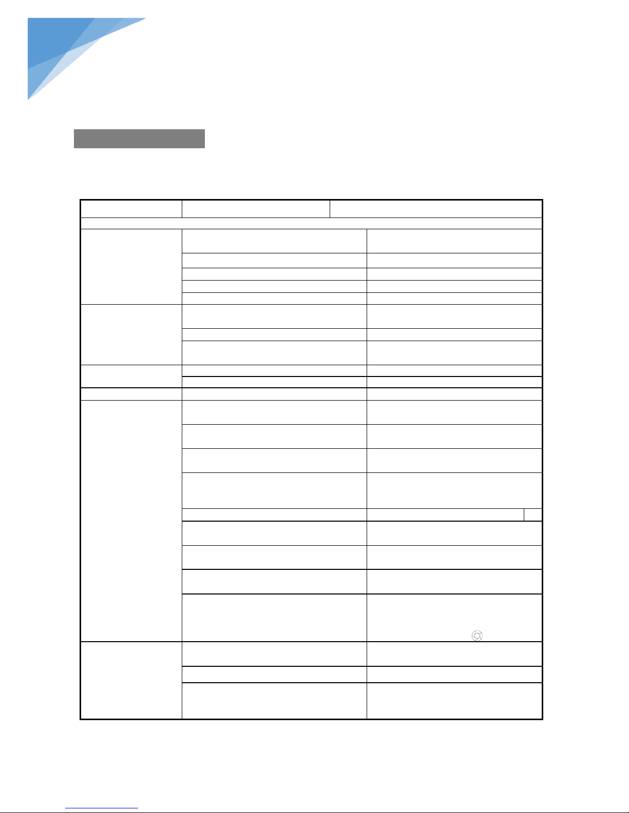
PROBLEM
REASON
SOLUTION
I. Optical Part:
1. The illumination is
opening, but the field of
view is dark.
The plug of the lamp holder is not connected
into the illumination set
Connect them well
The bulb burnt out
Change a new lamp
The brightness is too low
Adjust to a proper position
The color filter is piled too much
Minimize the number of the filters
No use the appointed lamp bulb
Use the specified halogen Lamp 6V30W
2. The edge of the field
of view has shadow or
the brightness is
asymmetry
The nosepiece is not in the located position
Turn the nosepiece into the position where
you can hear “clicked”
the color filter is stopped midway
Insert deeply
The phase contrast slider is not located in the
proper position
Turn the slider into the “clicked” position
3. Find dust and stain in
the field of view
There are stains on the specimen
Change a clean specimen
There are stains and dust on the eyepiece
Clean the eyepiece
4. Appear double image
the size of the aperture diaphragm is too small
Open up the aperture diaphragm
5. Resolution problems:
Image is not
sharp;
The contrast is not
high;
The detail is not
clear;
Don’t obtain the
phase contrast
effect
The nosepiece is not in the center of the light
path
Ensure the nosepiece is turned into the
“clicked” position
the aperture diaphragm in the view of field is
opened too large or too small
Adjust the aperture diaphragm correctly
The lens (condenser, objective, ocular or
culture dish) become dirty
Clean all
In the phase contrast observation, the bottom
thickness of the culture dish is more than
1.2mm.
Use a the culture dish whose bottom
thickness is less than 1.2mm
Use a bright field objective
Change to the phase contrast objective
The condenser ring is not coincident with the
objective phase ring
Adjust the condenser ring to match the
objective phase ring
The light ring and the phase contrast kits is not
centered
Adjust the bolts to center them
The objective used is not fit to the phase
contrast observation
Please use the compatible objective
When looking at the edge of the culture dish,
the phase contrast ring and the light ring is
deviated each other
Moving the culture dish until you obtain
phase contrast effect. You also can demount
the slider, dail the field diaphragm with the
direction of “ ”
6. One side of the image
is unfocused
The nosepiece is not in the center of the light
path
Insure the nosepiece is in the “clicked”
position
The specimen don’t place properly
Place the specimen on the stage correctly.
The optical performance of the culture dish
bottom is poor (such as erode figure and soon)
Please use a regular culture dish
STEINDORFF
5. Troubleshooting
Under certain condition, some no-fault factors will bring a reversible influence to the instrument’s
performance. If the problem is happened, please take proper measures according to the follow table. If you can’t
solve the trouble by the supplied methods, please contact with the sales department of our company.
Page 35
34
®
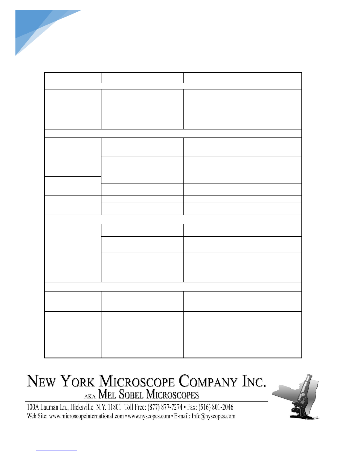
PROBLEM
REASON
SOLUTION
PAGE
II. Mechanical Part:
1. The coarse focus
knob is hard to run
The tension adjustment collar is too
tight
Loose properly
8
2. The image can’t stay
on the focal when
observation
The tension adjustment collar is too
loose
Tighten properly
8
III. Electric Part:
1. The lamp can’t light
No power supply
Check the power cord, and connect
them exactly
6
the installation of the bulb is wrong
Install the bulb correctly
3
The bulb burn out
Change a new bulb
3
The bulb burns out in a
high frequency
Not use the specified lamp
Use the required lamp
3
1. The height of the
brightness is not
enough
Not use a appointed lamp
Use an appointed lamp
3
The brightness adjustment knob is
used wrong
Adjust the brightness adjustment
knob in a correct way
8
2. The light glimpse
The bulb is going to spoil
Change the bulb
3
The power cord have a poor contact
Check the power cord, and connect
them exactly
6
Ⅳ. Viewing tube
The two eyes’ field of
view is different
The interpupillary distance is not
correct
Adjust the interpupillary distance
10
The diopter is not right
Adjust the diopter
10
Not adapter to the microscope
observation
When observing, do not stare at the
specimen but at the whole field of
view, or move the eyes away to see
other things, then back into the
objective
Ⅴ. Microscope video
1. The image is
unfocused
Focus incorrectly
Adjusting the focus system, make
the double reticle and the specimen
distinctly to see
10
There is faintness
around the image
It is a inherent character of the
achromatic objective
The problem is unavoidable if you
used an achromatic objective
3.The indoor window or
the fluorescence lamp
develop
The extra light entered into the
eyepiece and viewfinder is reflected
Cover up the eyepiece and the
viewfinder of the microscope
illumination system
STEINDORFF
 Loading...