

Page 1
Page 2
Hardware developed and manufactured by
Osnabrücker Str.1
49328 MELLE-BUER
Federal Republic of Germany
Phone: + (0)5427-1691
FAX: + (0)5427-6416
Email: info@wk-audio.de
WK-Audio ID Operation Manual
by d.popow@musicandtext.com
Preface by Martin Stahl
The information in this document is subject to change
without notice and does not represent a commitment
on the part of WK-Audio and/or Steinberg Media
Technologies GmbH. No part of this publication may
be copied, reproduced or otherwise transmitted or
recorded, for any purpose, without prior written
permission by WK-Audio and Steinberg Media
Technologies GmbH.
All product and company names are ™ or ®
trademarks of their respective owners.
© WK-Audio 2004
All rights reserved.
Page 3

Safety First!
Safety First! – 3
Page 4

❊
❊
❊
❊
: Safety First!
❊
❊
❊
❊
❊
❊
❊
❊
❊
❊
❊
❊
❊
❊
❊
❊
Packing List
WK-Audio ID – Basic unit
Mains cable
USB standard cable
Installer-CD-ROM, contents:
• Nuendo version 2.1
• Driver installation software
• WK-Audio ID Operation manual
• ReadMe file
System Requirements
To be able to use your WK-Audio ID, you will need
the following:
PC with a processor that runs at 1.5 GHz or faster,
a free USB port (type 1 or better) and
at least 1 Gigabyte of free RAM space.
Windows XP.
Nuendo software version 2.1 or later.
WK-Audio ID Driver software.
Safety Warning
N
OTE
:
Mains electricity is dangerous and can kill.
Within the WK-Audio ID, mains voltage is present.
Do not remove any WK-Audio ID cover with mains
connected! Check your mains wiring and earthing
before your switch the WK-Audio ID on.
The WK-Audio ID chassis is always connected to
mains earth to ensure your safety.
Do not remove the mains earth connection!
Safety Precautions
Make sure that the 230/115V switch on the ID rear
panel is set correctly before you attach the power
cable to an AC outlet!
N
OTE
:
The ID basic units with the serial numbers
ID1-0310-04 to ID1-0310-20 and the optional
Fader Modules with the serial numbers ID1 – 031201E to ID1 – 0312- 04E as well as ID1 – 0310-02E
to ID1 – 0310-05E are equipped with an internal
230/115V switch. If you have one of these units, you
should definitely read the extra information that is
supplied with these units. It explains the steps that
are necessary to change the setting of this switch.
Be sure that the ID mains connection cable is only
routed in a way that nobody can walk on or trip over
it, thereby accidentally cutting mains supply.
If you use a mains extension cable, make sure that
the overall power consumption of all connected
devices does not exceed its maximum capacity.
Before cleaning the WK-Audio ID, disconnect the
mains connection. Do not use chemicals, solvents
and abrasives for cleaning. Use a lint-free cloth and a
soft brush.
Prevent damage by avoiding exposure to fluids, dirt,
dust heat and smoke.
Prevent external objects from falling and liquids from
spilling into the appliance. Objects could fall on parts
that carry voltage (live parts) or cause a short circuit,
which could lead to fire or electric shock. Liquids could
lead to electric shock and damage the appliance.
Do not open the appliance as this will expose parts
that carry voltage. Do not attempt to service the
appliance beyond what’s described in the operation
manual. All other servicing should be referred to
qualified service personnel.
The appliance should never be used near water or in
moist places.
The appliance should only be used with a stand that
is recommended by the supplier.
The appliance should not be exposed to room
temperatures of less than 5°Celsius (41° Fahrenheit)
or more than 40° Celsius (104° Fahrenheit). Prevent
Avoid large variations in temperature and dampness
to prevent condensation which may short circuit the
appliance.
All electromechanical parts must be used in a proper
fashion to ensure long-term trouble-free operation.
Safety First! – 4
Page 5

Table of Contents
Table of Contents – 5
Page 6

: Table of Contents
Safety First! 3
Packing List 4
System Requirements 4
Safety Warning 4
Safety Precautions 4
Table of Contents 5
Foreword 7
Chapter Overview 7
Introduction 9
Chapter Overview 9
Welcome 10
ID Features 10
ID User Interface 11
Getting Started 13
Chapter Overview 13
Connecting the ID 14
The ID Driver Software 14
ID Driver Installation 14
Nuendo Settings 14
ID Control types 15
Motor Faders 15
Encoders with Key function 15
Square Function Buttons 15
Assigning User Functions 16
Round Function button 16
Potentiometers 16
Transport Controls 16
Trackball 16
ASCII Keyboard 16
Jog Wheel 16
The Edit Section 17
Chapter Overview 17
The ASCII Keyboard 18
ASCII Mode 18
Reverse Mode 19
Goto Mark Mode 19
Function buttons above the ASCII Keyboard 20
Window Function buttons 20
Grid Function buttons 20
Edit Function buttons 21
Global Function buttons 22
The Transport Controls 22
Locator/Preroll Displays 22
Function buttons in the Transport section 23
Preroll, Postroll, Punch & Locator Function Buttons
23
Cycle, Click, Edit Mode, Sync, Marker and other
Function buttons 24
Timecode Display 24
The Jog Wheel 25
Jog Wheel Function buttons 25
The Fader Section 27
Chapter Overview 27
The Fader Bank 28
Fader Function buttons 28
Fader Deviation Indicators 28
Select & Flip buttons 28
Track name displays 28
The Encoders 29
General Functions 29
Scroll – Assigning Tracks/Channels 29
Bank Select – Assigning Track classes 30
The Expand function 30
The Channel Strip Section 31
Chapter Overview 31
The Basics 32
Local Assign 32
Multi Channel view 33
Single Channel View 34
Equalizer 34
Aux Assign 34
Channel Assign 35
Insert 1-8 35
Insert Assign 36
Assigning an Insert effect to a slot 36
Removing an Insert effect from a slot 36
Status Panning 37
VSTI 37
The General Functions Strip 39
Chapter Overview 39
Memory 40
VU/Select 40
Enc Sens 40
Parameter Bank 40
Double Digit Display 40
Select Dial 40
Bank Select 41
Scroll 41
Automation 42
The Monitoring Section 43
Chapter Overview 43
Solo 44
Master VU 44
Solo Dim 44
Talkback Dim 45
User Settings 45
Talk Button 45
Speaker Out Controls 45
Extern Return 45
Control Room Controls 46
Studios 1, 2, 3 46
Phones 47
Technical Specifications 49
Dimensions 50
Connections 50
Specifications 50
Table of Contents – 6
Page 7

Chapter
1
Foreword
Chapter Overview
This chapter contains a foreword written by Martin
Stahl, Steinberg’s Product Manager responsible for
the WK-Audio ID.
1 – 7
Page 8

Chapter 1: Foreword
When Steinberg introduced the first VST application,
probably only few people may have realised the significance of the technology or would have foreseen its
rapid market acceptance and high potential for further
development.
Only a few years ago, my own studio equipment consisted of an analog 24-track tape recorder, an analog
mixing desk, many 19” rack effect devices and hardware synthesizers. Such a typical analog studio was
expensive, it needed a lot of space and it was quite
inflexible. I often wished that I had more than one unit
of certain compressor device when I wanted to apply it
to yet another important channel. Not to mention the
desire for Total Recall, which really wasn’t up to much
then.
Nowadays, my studio has changed completely: it consists of a powerful PC as the command center, three
space-saving 19" TFT flat screen monitors, a high quality AD/DA converter and a surround speaker system.
Today, we smile about having been limited to the tape
recorder’s 24 tracks and using an additional compressor on track 57 is no problem anymore. All you have to
do is open the necessary VST PlugIn a second time and
there you have it. Presets that I have tailored to my
needs and saved once make my life a lot easier and
issues like Total Recall and complete automation have
become commonplace. You simply press “Ctrl-S” on
your computer keyboard and hundreds of instrument,
mixer and VST PlugIn parameters are stored. Tape
noise, loose cable contacts and crackling potentiometers are history – and development will of course not
stop there.
We believe that an increasing number of audio productions will be created and mixed solely based on VST
Workstations. There are already countless examples for
this type of production. But has this development
improved the sound of the final product? Then and now
this still depends on the people who are involved in the
production itself.
A good song is still a good song and a good sound
engineer will probably create a good mix – no matter
which technology he or she uses. The result therefore
always depends on who uses the respective technology. And this is where we get to the aspect that became
our starting point for developing the WK-Audio ID.
The development of integrated native Digital Audio
Workstation systems (DAW) has fundamentally
changed the way we use the tools in our studio today.
Especially in mixing, many new possibilities have
emerged. At the same time, some have also been lost.
Full of fascination I looked at the beautiful graphic frequency response curve display visible in the EQ PlugIn.
“That looks great, it will also sound great!” . Mesmerized I stared at the third decimal place in a text field that
controlled the level of a fader.
The new possibilities offered by the precise and graphically appealing user interface on the screen captured
my attention in such a way that a great deal of my concentration was simply used up.
Over and over I caught myself mixing according to the
graphics on screen instead of trusting my ears. But how
could I? It was virtually impossible to close my eyes
and at the same time move the mouse cursor in a circle
in order to control the replica of a frequency dial on the
screen. A mouse simply doesn’t provide the same
physical feedback as a dial. This becomes more evident
when you try to set a high pass and a low pass filter
simultaneously. It is simply impossible as there is only
one mouse available. Now imagine you want to do that
with your eyes closed… Here, the software world is
clearly less user-friendly than the hardware world.
Therefore, what was needed to rediscover mixing with
your ears instead of with your eyes was a hardware
tool that looks and feels like the good old analog mixing desk. This hardware solution would of course have
to offer the possibility to use all those fantastic new
functions that were not available on the old analog
desk. It would thus have to be a custom-made Controller for digital VST-DAWs.
In the past, a few attempts have been made to create
such a device. But these DAW Controllers carried the
burden of too many compromises – as many that it was
always necessary to fall back on using the computer
keyboard and the mouse. There again, a great deal of
the attention that should have been focused on hearing
was lost to concentrating on using the Controller. In
addition, you could develop a postural damage because
of the less than favourable ergonomic design of the
workplace.
Designing the WK-Audio ID started at this point. We
wanted to develop a VST Controller that seamlessly
combines the advantages of an analog mixing desk and
the manifold innovations provided by the VST world, so
that its user’s attention can be fully focused on what he
or she hears during recording, editing or mixing. An
Input Device that helps your creativity, that you like to
touch and that is simply fun to use. This ambitious task
was reached in a joint effort with WK-Audio, who developed and built this Controller together with us. This fantastic co-operation has produced a unique and
unparalleled production tool. The WK-Audio ID is
unique because of its innovative combination of recording, editing and mixing features with a number of
remarkable operational concepts like “Dial Editing”,
“Reverse Operation”, “Expand” or “Push Hold Detection”.
But we have also thought of the future: VST software
development progresses so fast that it was necessary
to make the WK-Audio ID future-proof as an investment. Therefore it has great reserves to grow further
with future software development. We have developed
a Controller concept that many of you have wanted. And
here it is – the WK-Audio ID.
Have fun reading this manual.
Martin Stahl
1 – 8
Page 9
❊
❊
❊
Chapter
2
Introduction
Chapter Overview
This chapter contains the following information:
A few introductory words.
A list of WK-Audio ID’s basic features
A short overview of the ID’s user interface sections
with cross references to parts in this manual where
you can find detailed information on the respective
section.
2 – 9
Page 10

Chapter 2: Introduction
❊
❊
❊
❊
❊
❊
❊
❊
❊
❊
❊
❊
❊
❊
❊
❊
❊
❊
❊
❊
❊
Welcome
Thank you for choosing the WK-Audio ID!
This Digital Audio Workstation Controller is made
of premium hardware components. It integrates
perfectly with the Steinberg Nuendo software and
lets you seamlessly control all major functions the
software has to offer. It will help you focus your
attention where it belongs: on the audio you are
recording, editing or mixing.
The basic unit alone features a large amount of direct
hardware controls. You can step through and assign
the available individual Nuendo channels or channel
banks to the available hardware motor faders and
Encoder dials.
Using the optionally available Fader Modules, you
can extend your direct control and access up to
120 channels at once.
The WK-Audio ID adheres to the latest standards in
hardware control surfaces. It also features many
unique functions not to be found anywhere else.
An Edit section with a jog dial, its built-in
multifunctional ASCII keyboard, its direct PlugIn
access and the advanced channel selection features
really make the WK-Audio ID superior.
Functions like Expand, Global Access and the
reverse view intelligence will set new standards in
terms of workflow and usability.
The WK-Audio ID and Nuendo were developed in
parallel always ensuring optimal cooperation
between soft- and hardware.
All controls on the hardware user interface have
been put in their respective positions with an
ergonomic benefit in mind. They were chosen to best
reflect and/or give you better access to the existing
Nuendo software features.
We are sure that, once you have quickly mastered
its handling, it will greatly enhance your workflow,
thereby helping you to reduce cost and gain flexibility.
We hope that you have fun using the WK-Audio ID!
ID Features
The basic WK-Audio ID version features:
Direct and far-reaching control of the Nuendo audio
recording software application from one central
point. Functions that are not yet accessible as well
as new software functions will be supported by
future Nuendo versions.
24 channels in direct access, switchable.
40 rotary push/pull Encoders in the basic version.
12 control room potentiometers
380 backlit keys, framed (10.000.000 key cycles)
More than 50 large displays for instant feedback.
ASCII keyboard
Trackball, protected against dust and water.
Jog dial for easy editing.
Channel Matrix.
Direct PlugIn parameter access. Load, edit and apply
VST instruments and effects directly from the
Controller.
Reverse intelligence – The keys on the ASCII
keyboard can be used as On/Off switches for the
last selected function type on up to 96 channels.
Talkback microphone and headphone preamp.
Digital control room remote
32 channel VU meter bridge (24 channel meters and
8 Master section meters). Each meter has 30
segments.
1 USB connector per unit.
Non-reflecting surface.
Chassis material: Aluminum and steel.
Metal support stand.
Expandable with up to four additional Fader Modules
to provide a maximum number of 120 directly
accessible channels. Each additional Fader Module
is basically a copy of the left half of the basic WKAudio ID version. It provides 12 large touch-sensitive
motor faders, 39 Encoder dials, 52 displays and a
great number of different keys.
Other custom options:
Fader Modules, Joystick, custom modification of
electronic components, hardware and design, e.g.
built-in analog preamps, different front covers, other
LED colours, different leather for padded arm rest.,
Meter Bridge removal, Wooden side panels:
Genuine mahogany etc.
2 – 10
Page 11
Chapter 2: Introduction
ID User Interface
Here’s a brief overview of the ID user interface sections with cross-references to the respective manual chapters.
❊
❊
❊
❊
❊
❊
❊
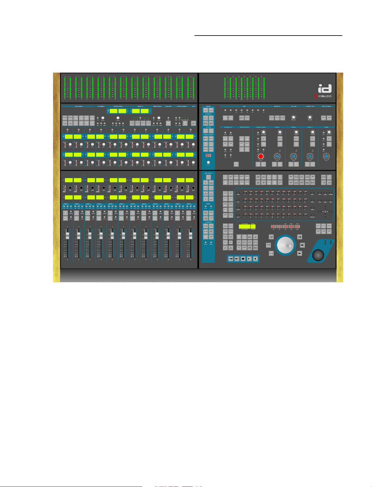
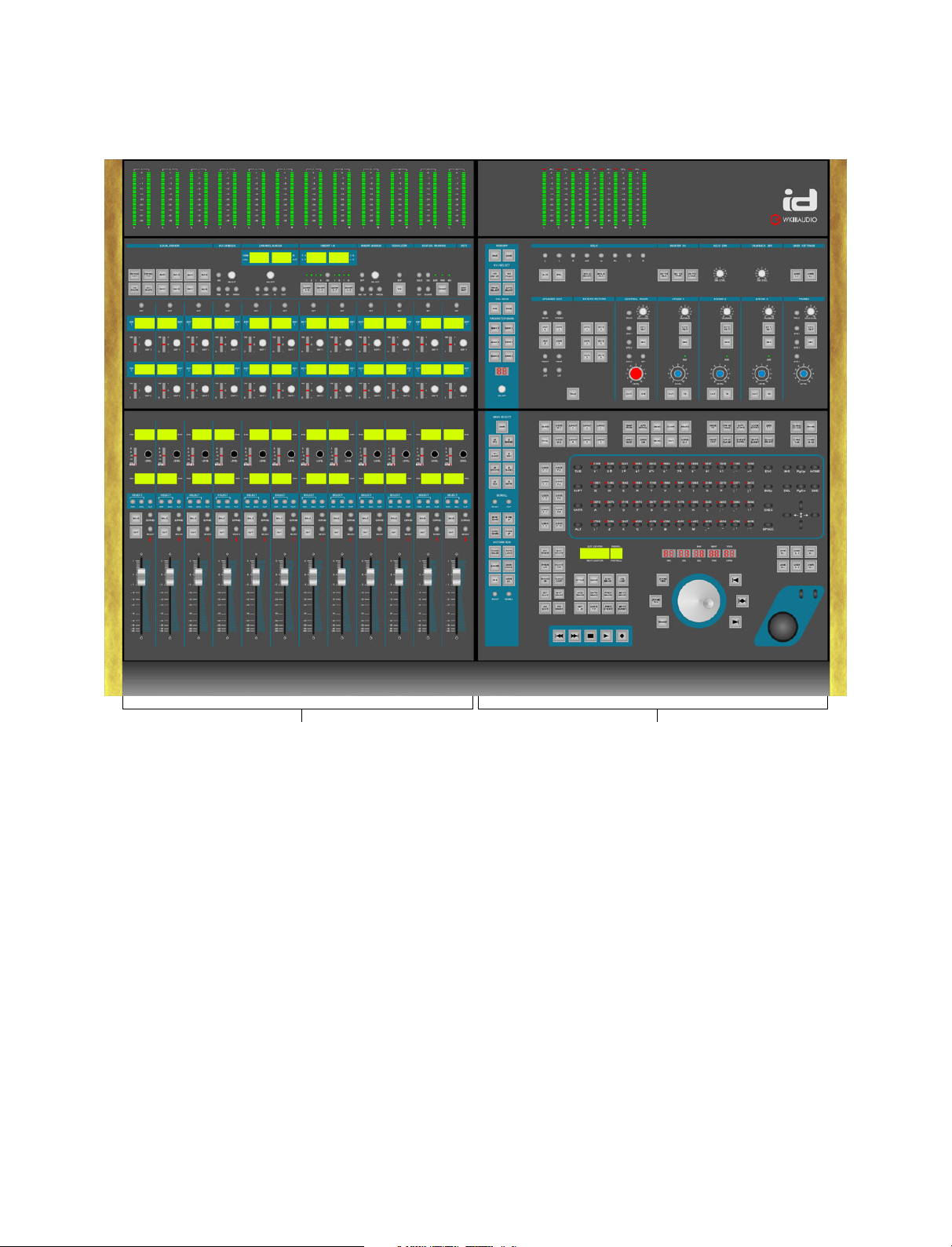
Fader Module
The basic ID version includes one Fader Module as
shown above. You can add four more for direct
access to 120 channels. Each Fader Module has the
following sub-sections (top to bottom):
Channel meter bridge
This shows the levels of the channels that are
currently assigned to the 24 hardware level controls
of each Fader Module.
Channel strip section
This is used to set Aux Send level and parameters,
Fader and Encoder gain and pan as well as channel
in/out routing for the selected channel. The Channel
strip section also lets select, activate and edit insert
effects and VST instruments and it provides you with
controls for complete EQ editing. See page 6-31.
Fader section
Here you can manually control the channel levels.
See page 5-27.
Master ModuleFader Module
Master Module
The Master Module has the following sub-sections
(top to bottom):
Master meter bridge
Lets you control the output bus(ses) and the level(s) of
the channel(s) currently selected on the Fader Module.
Monitoring section
Here you can select Solo modes and make other
settings related to monitoring. Details on page 8-43.
Edit section
This features an ASCII keyboard with three powerful
modes, a Trackball, a Jog wheel, many function
buttons and the Transport controls. See page 4-17.
General Functions strip
This is the vertical blue strip on the left side of the
Master Module. It provides many general functions like
Fader assignment, Nuendo project handling etc. Find
its full description on page 7-39. Its elements are also
described in context in other section chapters.
2 – 11
Page 12

Chapter 2: Introduction
2 – 12
Page 13

Chapter
3
Getting Started
Chapter Overview
This chapter contains the following information:
❊ A description of the ID driver software installation
process.
❊ What you must do to connect the ID to the “rest of
the world”.
❊ A description of the necessary settings that you must
make in Nuendo.
❊ Basic information about the various types of control
available on the ID.
3 – 13
Page 14
Chapter 3: Getting Started
Connecting the ID
Connecting the ID is a simple and straightforward
process. Do this:
1. Use the included mains cable to connect the ID to a
suitable and working mains socket.
2. Switch off your computer.
3. Using the included standard USB cable, connect the
USB bus on the ID to a USB bus on your computer.
4. If you wish, connect the balanced monophonic
L/R headphone inputs on the ID rear panel to an
appropriate sound source.
The signal will reappear on the two stereo phone jacks
located at the ID front side.
That’s all there is to connecting! Next, you must
install the driver software.
The ID Driver Software
The ID driver software that you have received with ID
must be installed on the computer that you use to
run Nuendo.
It is the link that interconnects the Nuendo software
and the ID hardware. It also allows you to completely
remote control the computer from the ID’s ASCII
keyboard.
The driver software is compatible with Windows XP®.
Driver software for Mac OS should be available in
the near future.
We recommend that you always use the latest ID
software driver version. This is available on the
Steinberg and WK-Audio web sites.
(www.steinberg.de or www.wk-audio.de)
NOTE:
“Digital signature not found”, “Do not install driver”,
“Driver not certified”.
Simply continue with the installation.
4. Restart your computer when the installation procedures have been completed.
You can safely ignore alert messages like
Nuendo Settings
To allow Nuendo to recognize the ID and establish
communication with it, you must make the following
settings in Nuendo:
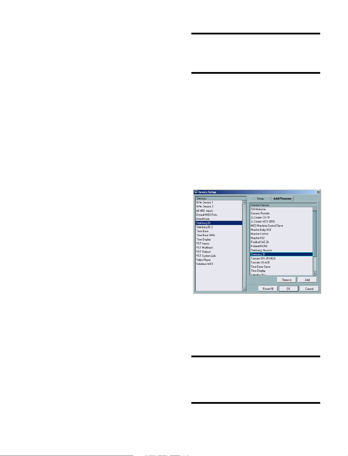
1. Open the Device menu and select “Device Setup…”.
The Device Setup dialog appears
2. Open the “Add/Remove” tab and select the ID in the
list to the right. Then click the Add button.
The ID has now been added to the Devices list on the left
side of the dialog.
ID Driver Installation
To install the driver software, proceed as follows:
1. Make sure the ID is properly connected to the USB
bus on your computer.
2. Switch on the ID, then switch on your computer and
let it boot up.
The automatic hardware recognition of your computer’s
operating system will detect the ID as a new USB device
and ask you for the driver software.
3. Insert the Driver CD into your CD-ROM drive and
follow the instructions displayed on your computer
screen.
The necessary driver software – a Firmware Loader and
the actual Time Base driver – will now be installed during
two separate installation processes.
3 – 14
3. Select it there. Then select the MIDI in- and outputs
you want to use on the respective pop-up menus.
4. If you wish and know what you are doing at this
point, you can now also freely assign any Nuendo
function to any of the available ID User Function buttons. If you are not sure yet, leave that for now, read
on and find the information on page 3-16.
NOTE:
to use the Nuendo project template file and the
Nuendo Preferences file that come on the ID Driver
CD-ROM. You can later always create and save your
own changed settings.
To keep things simple, you may first want
Page 15
Chapter 3: Getting Started
ID Control types
This section contains basic information about the
various types of control available on the ID.
Motor Faders
Each ID Fader module holds 12 touch-sensitive
100 mm motor faders.
● Moving a fader handle upwards increases the audio
level of the respective channel, moving it downwards
decreases it.
Encoders with Key function
In its Fader section, ID provides a great number of
rotary dials called Encoders. The Level and Edit
Encoders are examples for this.
Encoders can be used in several ways:
● To increase a level or a parameter value, turn the
Encoder clockwise, to decrease it turn counterclockwise.
● To switch to a parameter or overcome a safety precaution, press the Encoder as if it were a button.
what it would be like to mute a channel at a certain
point.
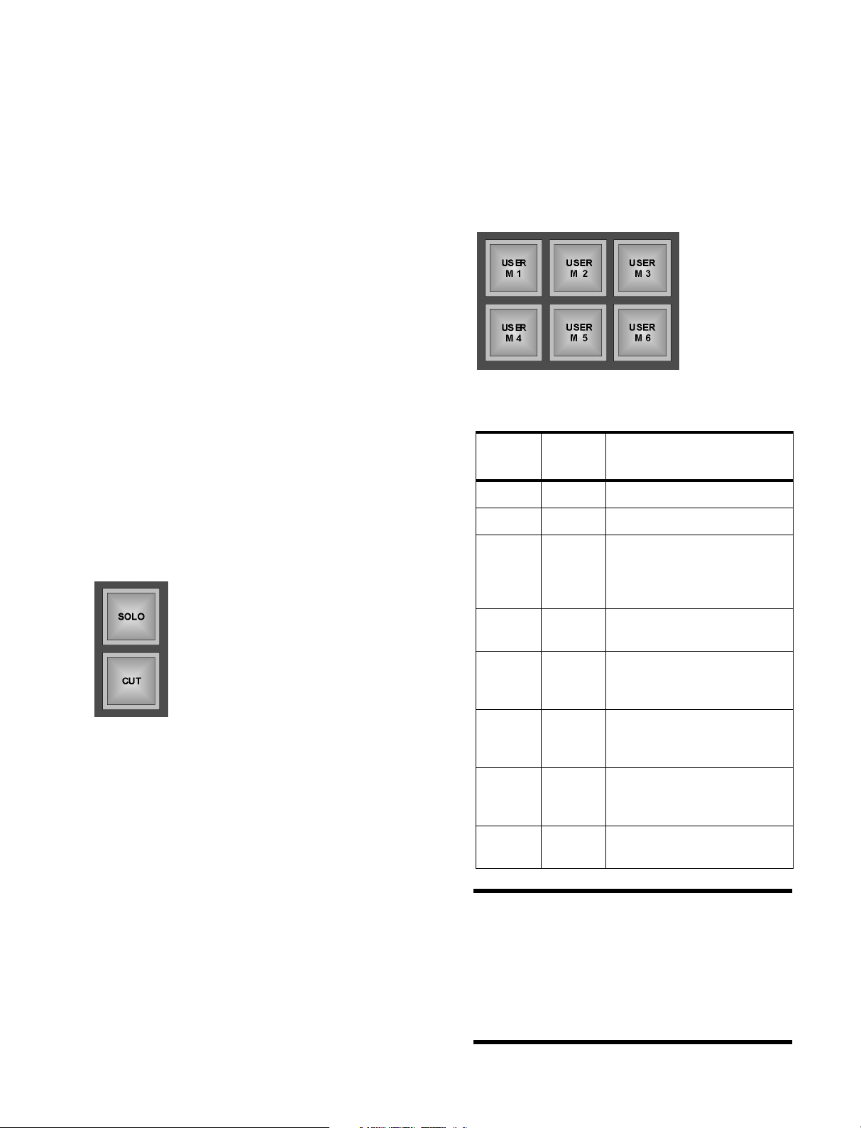
User Function buttons
Single and groups of User Function buttons have
been positioned in various places on the ID user
interface. You can freely assign any Nuendo function
to any of these buttons.
User Function buttons
This is where you find them:
No. of
buttons
6 User M Above the trackball.
1 User T Above the transport controls.
Default
Names
Position
Square Function Buttons
Square Function buttons will light
up when you activate a function by
pressing its button.
The square Function buttons on
the ID come in two flavours:
Fixed Function buttons
Each of these buttons is used to activate/deactivate
one predefined function.
Fixed Function buttons are equipped with two modes:
● If you press the button very briefly, the corresponding
function (e.g. Solo) will be activated. If you briefly
press the button again at a later time, the function
will be deactivated.
● Pressing a Fixed Function button for longer than 250
milliseconds will activate the corresponding function
only for as long as you press the button. As soon as
you let go of the button, the function will be disabled
at once. We call this Push Hold Detection.
This is handy in many different mixing and editing
situations, e.g. when editing with the Jog Wheel and
its related Fixed Function buttons or when trying out,
1 User A In the Automation controls
group that you can find at the
bottom of the blue General
functions strip.
2 User C Under User Settings at the top
right of the Monitoring section.
2 User W In the Edit section, above the
top left corner of the ASCII
keyboard.
1 User G In the Edit section, in the sec-
ond group of ten buttons above
the ASCII keyboard.
1 User E In the Edit section, in the third
group of ten buttons above the
ASCII keyboard.
10 User F To the left of the ASCII key-
board.
NOTE:
tions to these buttons, you can of course create your
own name tags for them. Simply print them on transparent overhead foil using a laser printer.
NOTE:
Push Hold Detection or Bounce Repeat, as it could
lead to confusing results.
Once you have assigned Nuendo func-
User Function buttons do not provide
3 – 15
Page 16

Chapter 3: Getting Started
Assigning User Functions
User Function buttons are described
on the previous
page.
Proceed as follows
to assign the
desired functions to
the ID User Function
buttons:
1. Select “Device Setup…” on Nuendo’s Devices menu.
2. In the appearing Devices Setup dialog, select the ID
If it’s not available, select the ADD/Remove tab to add it to
the list, then select it.
3. Open the Setup tab and assign the desired functions to the ID User Function buttons. To do this,
open the local pop-up menus by clicking in a column
next to the User Function button you want to assign
a function to.
Round Function button
Trackball
The Trackball is a convenient mouse replacement.
● Roll the ball to move the cursor on the Nuendo
screen and use the buttons as left and right mouse
buttons.
ASCII Keyboard
These can be found all over the ID user interface.
Pressing one of these buttons lets you either
activate/deactivate a function or toggle between two
switch states. Round function button are equipped
with Push Hold Detection, see page 3-15.
Round Function buttons
Potentiometers
ID’s potentiometers are all located in the Monitoring
section. They are rotary dials that have a start and an
end point and are used to set volume levels.
● To increase a level, turn the potentiometer clockwise,
to decrease it turn counterclockwise.
Transport Controls
This is an ASCII keyboard, similar to your computer
keyboard. It has unusual keys and additional modes
that help to improve your workflow. These are
described in the Edit Section chapter.
Jog Wheel
This is a heavy-weighted, high-resolution Jog wheel
with additional function keys for quick positioning
and editing in Nuendo. This is also described in the
Edit Section chapter.
These buttons let you remote-control the Nuendo
transport controls. The transport controls do not
provide Push Hold Detection.
3 – 16
What’s next?
The following chapters describe the individual ID
sections. Please read them carefully. The time that
you invest here is well-spent.
Page 17

Chapter
4
The Edit Section
Chapter Overview
This chapter contains the following information:
❊ A description of the ASCII keyboard and its three
modes.
❊ A description of all other elements in the Edit
section.
4 – 17
Page 18

Chapter 4: The Edit Section
The ASCII Keyboard
The ASCII keyboard on the ID more or less looks like
your usual computer keyboard. As its main task is
usability in a studio environment and not typing
letters, its keys have been optimized and differ in
shape from an ordinary keyboard.
The function buttons located to its left or any other
ID function buttons may be used as its function keys.
NOTE:
You can freely assign any Nuendo function to any
function button on the ID, see page 3-15.
The Trackball is used as a mouse replacement.
● Roll the ball to move the cursor on the Nuendo
screen and use the buttons as left and right mouse
buttons.
The ID ASCII keyboard has three operation modes:
ASCII, Reverse and Goto Mark.
Reverse and Goto Mark mode offer additional
options.
NOTE:
The ASCII functionality is not available in Reverse
and Goto Mark modes.
ASCII Mode
ASCII mode is the default mode of the keyboard.
In this mode, the keyboard works like any other
computer keyboard.
Same as on a usual ASCII keyboard – and differing
from the other buttons on the ID – the keyboard keys
will repeat their signal for as long as you press them.
This is called Bounce Repeat.
If you use a Windows computer, bounce (repeat)
time can be set under Control Panels/Keyboard
Properties.
When you scrub-play, you should thus use the
keyboard keys instead of the User function buttons
as the latter do not provide bounce repeat.
4 – 18
NOTE:
The ID keyboard always uses an English/US keyboard layout, even when you have selected another
layout for the connected computer. If you have, some
key commands may not work properly. We therefore
recommend that you use the English/US keyboard
layout on your computer.
Page 19

Chapter 4: The Edit Section
Reverse Mode
In Reverse mode, the keys on the ASCII keyboard
become a matrix of On/Off switches for the last
selected function type.
The LEDs above each key represent the On/Off
status of the current function for each of the
channels.
The individual keys on the keyboard represent the
channels 1-48 or 49-96.
You get complete overview and can therefore quickly
activate or deactivate the same function type – e.g.
Record Ready, Solo etc. – for many channels.
The shape of the keyboard keys helps you to
increase setting speed. You can simply run your
finger over the keys of several adjacent channels in
one go.
Proceed as follows to activate Reverse mode:
1. Press the REVRS button, located above the top right
of the ASCII keyboard.
Goto Mark Mode
In this mode, you can use the keys on the ASCII
keyboard to select Markers that you may have set in
Nuendo. You can directly jump to up to 96 Markers.
Proceed as follows to activate and use Goto Mark
mode:
1. Press the GOTO MARK button, located in the button
group above the ID transport controls.
This activates Goto Marker mode.
Press this button to activate
Reverse mode…
…and one of these
to select the group of channels that you want to affect.
2. Activate the CHAN 1-48 or the CHAN 49-96 function button (located below the REVRS button) to get
access to the respective channels.
3. On the Fader module, use (and thereby select the
desired function. This must be done for at least one
channel.
Now you can use the keys on the keyboard to activate or
deactivate the selected function for other channels. The
LEDs above each key provide optical feedback.
4. If you select another function on the Fader module,
the LEDs will reflect its current status on all channels
and you can start to change that.
NOTE:
If Reverse mode was active before, it will automatically be deactivated.
2. Select the CHAN 1-48 or the CHAN 49-96 function
button to be able to jump to Markers 1-48 or 49-96,
respectively.
3. Press a key on the keyboard to jump to the desired
Marker in Nuendo.
4. To disable Goto Marker mode, simply press the
GOTO MARK button again.
4 – 19
Page 20

Chapter 4: The Edit Section
Function buttons above the ASCII Keyboard
This section describes all Fixed Function buttons above
the ASCII keyboard, starting with the MIXER button in
the first group of ten above its left upper corner and
ending with the CHAN 49-96 button in the group of
four buttons, located above its right upper corner.
Window Function buttons
Button Description
Lets you open or close Nuendo’s
Mixer window.
If Nuendo is not yet running, you can
press this button to boot it.
USER W 1 and 2 are user-definable
Function buttons. Read “Assigning
User Functions” on page 3-16 for
more information.
LAYOUT buttons 1 through 6 let you
open different Nuendo Window
Layouts
Grid Function buttons
Button Description
Press this several times to step
through the available Snap modes.
Lets you switch Nuendo’s Autoscroll
function On or Off.
Remote-controls Nuendo’s Undo
function.
Remote-controls Nuendo’s Copy
function.
Remote-controls Nuendo’s Paste
function.
4 – 20
Opens the Nuendo Pool window
Press this several times to step
through the available Grid size values.
Activates or deactivates Snap to
Grid.
Remote-controls Nuendo’s Redo
function.
Remote-controls Nuendo’s Cut
function.
Page 21

Chapter 4: The Edit Section
Button Description
USER G 1 is a user-definable Function button. Read “Assigning User
Functions” on page 3-16 for more
information.
Edit Function buttons
Button Description
Press this to create a Fade in for one
or several currently selected Events.
The Fade in starts at the Event start
and ends at the current Project Cursor position.
Creates a Crossfade between the
selected Event(s) and its/their neighbour Event(s). If the Events overlap,
the Crossfade gets the same length
as the overlap. If you process Events
adjacent to another and they possess
enough “hidden” audio, the crossfade will get the Default fade length
set in the Crossfade Editor . If they
don’t, no crossfade happens.
Button Description
Press this to create a Fade out for
one or several Events. The Fade out
starts at the current Project Cursor
position and ends at the Event end.
Pressing this will split the Event at the
current Project Cursor position.
Pressing this positions the start of – if
available – the Snap point of the
selected Event at the current Project
Cursor position.
Mutes the currently selected Event.
This button does exactly the same as
the Bounce Selection function on
Nuendo’s Audio menu. It lets you create a new audio file based on one or
several Events that you have edited.
If you don’t know this function, we
recommend that you look up the
Nuendo manual.
S-PT CURS stands for “Snap point
to Cursor” and that’s what you do
here: Pressing this button will create
a Snap point at the current Project
Cursor position. This function is
applied to the currently selected
Event(s).
Locks the current Event. Select
which parameters you want locked
on the Editing tab of Nuendo’s Preferences dialog
USER E 1 is a user-definable Function button. Read “Assigning User
Functions” on page 3-16 for more
information.
4 – 21
Page 22

Chapter 4: The Edit Section
Global Function buttons
Button Description
Use this to activate Global Access
mode. If this is active, you can carry
out an operation in one go for all
Tracks, e.g. set Aux Send level for all
mixer channels. This is available for a
number of Nuendo functions. Please
find a list at the bottom of this column.
This lets you activate or deactivate
the ASCII keyboard’s Reverse mode.
This is described on page 4-19 in
this chapter.
The Transport Controls
The ID Transport controls are the twins of Nuendo’s
transport controls.
Button Description
Rewind, Zero
Fast Forward, Project end
Stop
This button is used to assign channels 1-48 to the keys of the ASCII
keyboard in Reverse and Goto Mark
modes. Please look up page 4-19 in
this chapter
This button is used to assign channels 1-48 to the keys of the ASCII
keyboard in Reverse and Goto Mark
modes. Please look up page 4-19 in
this chapter
Global Access functions
EQ band 1 On EQ band 2 On
EQ band 3 On EQ band 4 On
EQ bypass, Sends bypass,
Sends slot 1 On Sends slot 2 On
Sends slot 3 On Sends slot 4 On
Sends slot 5 On Sends slot 6 On
Sends slot 7 On Sends slot 8 On
Sends slot 1 pre/post Sends slot 2 pre/post
Sends slot 3 pre/post Sends slot 4 pre/post
Sends slot 5 pre/post Sends slot 6 pre/post
Sends slot 7 pre/post Sends slot 8 pre/post
Start
Record
To make a Track record ready, use
the Ready buttons in the Fader section, see page 5-28.
NOTE:
on the Transport tab of Nuendo’s Preferences dialog.
You can make special Wind Speed settings
Locator/Preroll Displays
These backlit displays below the left lower corner of
the ASCII keyboard show the current Left and Right
Locator settings as well as the currently set Pre/Post
roll times. You can make these settings using the
corresponding Function buttons to the left of the displays.
4 – 22
Page 23

Chapter 4: The Edit Section
Function buttons in the Transport section
These two blocks of buttons above the Transport
controls are used to make Transport and Marker
related settings.
Preroll, Postroll, Punch & Locator Function Buttons
Button Description
Press this button one or several times
to set the desired preroll time. The
value type used here (sample rates,
seconds, frames etc) depends on
what’s used in the Project.
Press this button one or several times
to set the desired postroll time. The
value type used here (sample rates,
seconds, frames etc) depends on
what’s used in the Project.
This lets you activate or deactivate
preroll.
This lets you activate or deactivate
postroll.
Use this to activate or deactivate
automatic Punch in.
Use this to activate or deactivate
automatic Punch out.
If you activate this Function button,
you can set the left Locator position
to the current Project Cursor position.
If you activate this Function button,
you can set the right Locator position
to the current Project Cursor position.
Press this to move the Project Cursor
onto the position of the left Locator.
Press this to move the Project Cursor
onto the position of the right Locator.
4 – 23
Page 24

Chapter 4: The Edit Section
Cycle, Click, Edit Mode, Sync, Marker and other Function buttons
Button Description
Use this to activate or deactivate the
Cycle function. For this to work as
expected, the Locators should be set
to useful positions.
Sets Click to On or Off.
Use Metronome Setup on Nuendo’s
Transport menu to make the desired
metronome settings.
Press this button to activate or deactivate Edit mode in Nuendo. This is
useful if you work with audio and
video in conjunction
Press this button to activate or deactivate external synchronization.
Press this to add a new Marker at the
current Project Cursor position.
Button Description
Pressing this lets you select the previous Event on the selected Track.
Pressing this lets you select the next
Event on the selected Track.
Timecode Display
This display shows the current Nuendo Project
Cursor position in hours/minutes/seconds/frames/
sub-frames or ticks/samples, depending on what you
currently do in Nuendo.
Pressing this button activates or
deactivates the Goto Mark mode of
the ASCII keyboard. you can then use
its keys to directly jump to Markers.
Read more on page 4-19.
Press this button to let the Project
Cursor jump to the previous Marker.
Press this button to let the Project
Cursor jump to the next Marker.
If you press this Function button, the
Locators are set onto the start and
end position of the currently selected
Event.
USER T 1 is a user-definable Function button. Read “Assigning User
Functions” on page 3-16 for more
information.
4 – 24
Page 25

Chapter 4: The Edit Section
The Jog Wheel
The Jog wheel and its related controls
The Jog wheel on the ID is heavy-weighted and highresolution (4000 values per turn of the wheel).
It has two basic functions:
❊ You can use it to position the Project Cursor in
Nuendo. The step width is automatically set to the
step width set for the edited Nuendo function
(e.g. bars/beats, timecode, samples etc).
❊ You can use the Jog wheel to select and edit Events
in Nuendo.
NOTE:
under Cursor” function on the Editing tab of
Nuendo’s Preferences dialog must be active and at
least one Nuendo Track must be selected, as Autoselect always points to the selected Track(s).
Selecting Nuendo Tracks using the ID
On the ID, several methods for selecting Nuendo
Tracks are available:
● Press the FDR or ENC button in the blue SELECT
field above the respective ID fader.
To select several Tracks, simultaneously hold down
the CNTR key on ID’s ASCII keyboard. (which must
be in ASCII mode, see page 4-18).
To deselect already selected Tracks, hold down the
SHFT key.
● Use the Arrow Up Down buttons on ID’s ASCII keyboard.
● If the ASCII keyboard is in Reverse mode, you can
select one Track at a time by directly pressing the
desired key on the keyboard.
For this to work, the “Auto-select Events
Jog Wheel Function
buttons
Six Function buttons are grouped around the Jog
wheel. These are used to activate or deactivate the
Jog wheel positioning and editing modes.
Here are the options that you get when you activate
one of the buttons to the left or right of the Jog wheel:
Button Description
You can press ZOOM TIME and turn
the Jog wheel clockwise to horizontally
magnify Tracks/Events. Turn the wheel
counterclockwise to zoom out again.
You can press ZOOM TKS and turn
the Jog wheel clockwise for vertical
magnification of all Tracks. Turn the
wheel counterclockwise to zoom out
again.
If you press RANGE, the resolution of
the Jog wheel is automatically set to
sample steps in all grids (based on the
sample rate used).
This button is called NUDGE EVENT
START. When it is active, you can use
the Jog wheel to change the playback
start within Events and thus resize
them. The step width of this function
depends on the grid settings in
Nuendo. You can set it by pressing
the GRID SIZE button, located in the
second button group above the ASCII
keyboard. Find more information about
GRID SIZE on page 4-20.
This is called MOVE EVENT. If you
activate it, you can use the Jog wheel
to move the current time position of the
selected Event(s). Here too, the GRID
SIZE setting defines the step width.
This button is called NUDGE EVENT
END. When it is active, you can use
the Jog wheel to resize the end of an
Event. The step width of this function
depends on the grid settings in
Nuendo. Use the GRID SIZE button to
change it according to your wishes.
NOTE:
tons will greatly enhance your work flow efficiency.
Using Push Hold Detection on these but-
4 – 25
Page 26

Chapter 4: The Edit Section
4 – 26
Page 27

Chapter
5
The Fader Section
Chapter Overview
This chapter describes…
❊ The channel level controls: Faders and Level
Encoders.
❊ All other elements in the Fader section, like Solo,
Cut, Expand etc. and how to assign Tracks/Channels
to Faders and Level Encoders.
❊ A description of those functions on the General
functions strip that have an effect on Faders and
Level Encoders. The General functions strip is the
blue vertical strip between the Master and the Fader
Module.
5 – 27
Page 28

Chapter 5: The Fader Section
The Fader Bank
Each Fader Module has twelve 100 mm touch-sensitive motor faders, each with a number of Function buttons, a
Fader Deviation Indicator LED and a backlit Track name display. The Faders always reflect the current settings.
Fader Function buttons
Each Fader strip has the following Function buttons:
Button Description
Pressing this button will mute all
Tracks that are not soloed. This is a
solo-in-place function.
If you press Cut, the corresponding
Track will be muted.
If you press EXPAND on a Fader
strip, all incoming connections to the
corresponding channel are analyzed
automatically and lined up on the ID
faders for level editing. Read more on
page 5-30.
This lets you activate or deactivate
record-ready status for the respective
Track.
Fader Deviation Indicators
These two LEDs indicate whether the Fader
has been moved from its original position as
well as the direction into which it has been
moved. If you let go of the Fader handle, the new
Fader position becomes the new starting point.
With an automation mode active, see page 7-42,
this will only work as expected, if an automation
breakpoint is available in the following timecode. It
may therefore happen, that one of the two LEDs is
still lit, although you have let go of the fader after
writing automation data with it. You can change this
by simply touching the fader once again.
Select & Flip buttons
The FDR and ENC buttons
let you select the Channels
(Tracks) assigned to the
Fader and to the Level
Encoder. Using the FLIP button, you can individually
swap a Channel between Fader and Level Encoder. You
can also flip the complete Fader bank, see page 5-29
NOTE:
ASCII keyboard’s Reverse mode to get complete
overview of the current status of each of these buttons on all Tracks. Please read more on page 4-19.
5 – 28
It is a good idea and very handy to use the
Track name displays
Above the Select buttons, there is one Track name display
for each Fader. It reflects the Track’s name in Nuendo.
Page 29

Chapter 5: The Fader Section
The Encoders
Each Fader Module has twelve Level Encoders. a Cut function that you can activate by pressing the Encoder, a Cut
status LED, a 10-segment indicator that reflects the Encoder setting and a backlit Track name display.
Everything that was said about the Select and Flip buttons on the previous page applies here, too.
General Functions
The vertical blue strip
on the left side of the
Master Module
provides you with a
variety of functions that
enhance the
functionality of the
adjacent ID sections.
The functions that
concern Faders and
Level Encoders are
located in its lower half
and will be described
next.
Scroll – Assigning Tracks/Channels
Button Description
This is the “super version” of the individual FLIP buttons on each Fader
strip.
Pressing this button on the General
Functions strip will swap all Tracks/
Channels assigned to all Faders with
those assigned to the Level Encoders
and vice versa.
Use this button on the General Functions strip to restore your original
Track/Channel assignment setup.
Press this button to assign the previous bank of twelve Tracks/Channels
to the level controls.
Example: Tracks 13-24 are assigned
to the twelve Faders. Then you press
this button. Now Tracks 1-12 will be
assigned to the Faders.
Press this button to assign the next
bank of twelve Tracks/Channels to
the level controls.
Press CHAN DOWN to assign the
previous Track/Channel to a level
control.
Press CHAN UP to assign the next
Track/Channel to a level control.
5 – 29
Page 30

Chapter 5: The Fader Section
Bank Select – Assigning Track classes
Each of these buttons can be used to automatically
line up all Tracks of the respective channel class(es)
on the ID Faders and Level Encoders. You may e.g.
only wish to see and directly edit all Audio or all MIDI
Tracks, all Inputs, all Send busses or Returns. You
can also assign them altogether. The scrolling
options, mentioned on the previous page, apply.
Button Description
This may be used by functions available in a later Nuendo version.
If you only want to see and control
the input channels, press this button.
Then use the ID faders and Level
Encoders to change their levels.
Press this button to see and control
the output busses.
The Expand function
The Expand function is an extremely
useful tool during the mixing process.
Say, pressing the 05 GROUPS
Function button (described on this
page), you have layered all Group
Tracks across the ID Faders. But
now you want to know, which channels are routed to a specific group.
If you press the EXPAND button, all
incoming connections to Tracks are
analyzed and immediately lined up
on adjacent ID faders so that you
can edit them directly. Expand thus
arranges all sending channels next
to an Effect return channel or all
feeding channels next to a Group
channel.
NOTE:
classes MIDI, VST Instruments and Input.
Expand is not available for the Track
Pressing this button lets you see and
control the Audio playback channels.
Activating this lets you see and control the MIDI track volumes.
Use this button to assign the Audio
Groups to the ID faders and Level
Encoders.
If you press this button, the Effect
Return channel levels become visible
and can be controlled via the ID faders and Level Encoders.
If this is activated, all Tracks/channels
and channel classes are arranged
and assigned to the ID faders/Level
Encoders in exactly the same way as
in the Nuendo Mixer windows.
Press this button to see and control
the output busses of your currently
used VST Instruments.
Here’s what happens when you press EXPAND for
the different Track classes:
Track class This happens
Audio The respective Audio channel
gets the left-most Fader. Its
input channel is put next to it.
Group The actual Group channel gets
the left-most Fader where the
EXPAND button lights up.
Simultaneously, the individual
Group channels are opened
and lined up on the adjacent ID
Faders, where you can edit
them. You can hide them again
by pressing the illuminated
EXPAND button on the leftmost Fader strip.
FX Channel
Returns
Output busses All channels that are routed to
The corresponding Return is
moved to the left-most Fader
and all Tracks that send a signal
to this effect via their Aux Sends
are arranged next to it.
this bus are lined up.
5 – 30
Page 31

Chapter
6
The Channel Strip
Section
Chapter Overview
This chapter informs you:
❊ How you can use the elements in the Channel Strip
section to set Aux Send level and parameters, Fader
and Level Encoder gain and pan as well as channel
in/out routing for the selected channel.
❊ What you must do to select, activate and edit
insert effects and VST instruments.
❊ About using the EQ.
❊ About functions on the General functions strip that
have an effect on Channel Strip section controls.
The General functions strip is the blue vertical strip
between the Master and the Fader Module.
6 – 31
Page 32

Chapter 6: The Channel Strip Section
The Basics
What you activate or select in the upper part of the Channel Strip section…
…affects what you can see and do in its lower part.
Let´s start at the top left…
Local Assign
The Local Assign block has twelve parameter
buttons. If you activate one of these buttons, the Edit
displays in the lower part of the Channel strip
section show the different settings on all channels
for this particular parameter.
We call this a Multi Channel view.
Using the EDIT dials, you can change the respective
parameter setting for each channel. The display
above each dial gives you optical feedback.
If a parameter has more than one display page, you
can use the red-capped Select dial in the blue
General functions strip to select the other pages.
In Multi Channel view, the Edit displays and dials are
arranged in a similar fashion as the Faders and Level
Encoders in the Fader section. The upper row refers
to the channels that have been assigned to the Level
Encoders. The lower row refers to the channels that
are currently controlled by the Faders.
If none of the twelve buttons in the Local Assign
block is active, the displays in the lower part show
what we call a Single Channel view.
That is, a number of different parameters of one
channel only (the currently selected channel) is
shown and can be edited in the lower part of the
Channel strip section.
In Single Channel view, each Edit display and dial is
used to control a different parameter.
6 – 32
Page 33

Chapter 6: The Channel Strip Section
Multi Channel view
The following parameters can be displayed and
edited in Multi Channel view:
Button Description
Fader/Level Encoder gain control,
+/-48.2 dB.
NOTE:
the gain controls, as rough handling
can result in big jumps in level!
Fader/Level Encoder panorama
Page 1: Pan left/right
Page 2: Pan front/rear
Fader pan and front/rear
In this mode, both the upper and the
lower Edit Encoders refer to the Faders only (not to the Level Encoders!)
The upper row of Edit Encoders control left/right pan, the lower controls
front/rear position.
Especially useful in a surround mix as
you don’t have to switch.
Be careful when you use
Button Description
Same as above
Same as above
Same as above
Same as above
Same as above
NOTE:
either turning the Edit dial or by pressing it.
All On/Off functions may be switched by
Encoder pan and front/rear
In this mode, both the upper and the
lower Edit Encoders refer to the Level
Encoders only (not to the Faders!)
The upper row of Edit Encoders control left/right pan, the lower controls
front/rear position.
Especially useful in a surround mix as
you don’t have to switch.
Page 1 : Aux Send level
Page 2 : Aux Send On/Off
Page 3 : Aux Send Pre/Post
Page 4 : Aux Send destination
Page 5 : Aux Send bypass On/Off
Same as above
Same as above
6 – 33
Page 34

Chapter 6: The Channel Strip Section
Single Channel View
In this mode, the Edit dials and displays are used as follows:
Edit Encoders/displays
left to right
First eight in top row Aux Send level 1-8. Press the Edit Encoders to set the corresponding Aux
Lower row Encoders 1 and 2 Pan left/right and Pan front/rear.
Lower row Encoder 3 unused
Lower row Encoder 4 Channel/Track gain (not Aux gain!)
Lower row Encoder 5 Phase Reverse On/Off. Off = natural phase, On = phase is reversed. You can
Lower row Encoder 6 unused
Lower row Encoders 7 and 8 Surround pan for the selected Aux Send (which can be selected using the SET
Last four in top and bottom rows 4-band parametric EQ.
Description
Send to On or Off.
either turn or press the Encoder.
button located directly above the corresponding Aux Send display).
High band with additional high shelf and low pass settings.
Low band with additional high pass and low shelf settings.
There are two options to switch each band On/ Off:
By pressing the lower Edit Encoder.
By pressing the SET button above the respective band. The button will light up.
You can also switch between the parameters frequency and Quality (Q) by
pressing the upper Edit Encoder.
NOTE:
Encoder while you make a Q factor setting, the display will automatically switch back to frequency as
soon as you let go of the Encoder.
If you continuously hold down the Edit
Equalizer
If you activate the EQ button, all
EQ parameters of a single
channel are distributed onto the
first eight displays and Edit
Encoders where you can change
all parameter values.
You can use the BYP button to
bypass the Equalizer.
Aux Assign
The controls can be used to
activate Aux Sends for the
selected channel and make pre/
post settings for them.
Pressing SR lets you see all
available Surround panning
parameters in the displays.
The controls Select and Patch
will be used by functions available
in later Nuendo versions.
To patch (route) an Aux Send to
a destination, you can use page 4 in Multi Channel
view. How you can get there is described in the
bottom left of page 6-32.
● Select an Aux Send by pressing its SET button.
● Activate it by pressing the ON button in the Aux
Assign block. If desired, press SR.
● The PRE button lets you toggle between pre and
post fader settings. If the button is lit, pre fader is
active. if it isn’t it’s post fader.
6 – 34
Page 35

Chapter 6: The Channel Strip Section
Channel Assign
This block contains two 2-line displays, a SELECT
rotary dial and four buttons. The settings that you
make here apply to the currently selected channel.
The settings are shown in the displays.
● To set a parameter, press one of the buttons. It will
light up in red and you can select the desired setting.
Button Description
CH Channel – Lets you select a channel
or Track with the SELECT dial.
LABEL Channel/Track name ASCII input –
Not used at the time when this was
written. Will be used by functions
available in a later Nuendo version.
IN Input routing, lets you select an input
source with the SELECT dial.
Insert 1-8
The elements in this block can be used to display
which Insert effects are currently resident in which
slots and to select an Insert effect for editing with the
controls and displays in the Channel Strip section.
The two displays in this block show which Insert
effects are resident in the first or second four Insert
effect slots per channel.
● To display to the second group of four slots, use the
INS 5-8 button in the Insert Assign block, described
below.
The eight small LEDs indicate which Insert slots are
actually used.
● To select an Insert effect for full display and editing
with the Channel Strip controls, press one of the
square INSERT x/x buttons. To be able to select from
the second group of four effects, use the INS 5-8
button in the Insert Assign block.
OUT Output routing to Groups or one of
the busses. Use the dial.
NOTE:
7 and 8 are post fader.
● The ON button lets you switch the currently selected
Insert effect On or Off. If you switch it Off, its LED
will go out.
NOTE:
Off doesn’t remove it from its slot. Assigning and
removing effects to/from slots is done in the Insert
Assign block, described below.
The Insert slots 1 to 6 are pre fader, slots
Same as in Nuendo, switching an effect
6 – 35
Page 36

Chapter 6: The Channel Strip Section
Insert Assign
The controls in this block are
used to assign or remove Insert
effects to/from the available eight
slots.
Here you can also activate an
effect bypass for each slot and
select the second group of four
effects for display and editing
with the Channel Strip controls
as described above in the Insert
1-8 section.
NOTE:
slot or remove it from there, you must first activate
the PATCH button!
Assigning an Insert effect to a slot
Proceed as follows:
1. Activate the PATCH button so that it lights up in red.
2. Select the desired Effects slot by pressing the corre-
sponding INSERT x/x button in the INSERT 1-8
block. It will light up in red.
If necessary, use the INS 5-8 button to switch to the
second group of four slots.
3. Select an effect by turning the SELECT dial clockwise.
Nuendo will actually load the PlugIn ca. one second after
you have stopped to turn the dial.
4. Press PATCH again to get out of Insert Assign mode.
To be able to assign an Insert effect to a
Removing an Insert effect from
a slot
Do this:
1. Activate the PATCH button so that it lights up in red.
2. Select the desired Effects slot by pressing the corre-
sponding INSERT x/x button in the INSERT 1-8
block. It will light up in red.
If necessary, use the INS 5-8 button to switch to the
second group of four slots.
3. To remove the effect in the selected slot, turn the
SELECT dial counterclockwise and let go of the dial.
Nuendo will actually remove the PlugIn ca. one second
after you have stopped to turn the dial.
4. Press PATCH again to get out of Insert Assign mode.
The other buttons in the Insert Assign block
Button Description
BYP Activate this to activate Bypass for
the currently selected effect, i.e.
when this is active, the original signal
will not be routed through the effect.
INS 5-8 Nuendo provides you with 8 Insert
effect slots of which four can be
made visible in the INSERT 1-8
block. Use this button to display the
second group of four slots.
SR This will be used in connection with
future Nuendo versions.
PATCH As a precautionary measure, this but-
ton must be activated for you to be
able to assign or remove an Insert
effect to/from one of the slots.
6 – 36
Page 37

Chapter 6: The Channel Strip Section
Status Panning
In this block, there is
one more instance of
the SOLO and CUT
buttons, available
separately for each
Track/channel in the
Fader section
(see page 5-28).
This SOLO and CUT
button can be used to
solo or mute the Track/
channel that is currently
selected for editing. The intention behind this is to
help you to focus your attention on your editing
instead having to search for the respective buttons in
the Fader section.
Button Description
SOLO Activate this to set the currently
selected Track/channel to solo.
Cut Activate this to mute the currently
selected Track/channel.
ISO Activate this button to isolate the
selected Track/channel from Automation Read. As a result, you will hear
the Track/channel without automation.
VSTI
By activating the EDIT INST button, you
can distribute the parameters of a
currently resident VST instrument onto
the displays in the Channel Strip function
and easily edit them with the respective
dials.
1. Load a VST instrument using the ID
ASCII keyboard as usual.
2. Press the 08 INSTR button in the Bank
Select block of the General Functions
strip.
All currently resident VST instruments are
assigned to the Faders in the Fader section.
3. Select the new VST instrument by pressing the FDR
button in the blue SELECT area above its fader.
Now the parameters are distributed onto the displays and
dials in the Channel Strip section, where you can edit them.
NOTE:
than can be made visible and edited using the available displays and dials, use the red-capped SELECT
dial in the General Functions strip to switch to the
other parameter pages. The double digit numeric
display above the SELECT dial indicates the currently visible page.
If a VST instrument has more parameters
S-SAVE Solo Save – If you activate this, the
selected Track/channel will not be
muted if you solo other Tracks/channels. Use can for example use this to
prevent that a Click track is being
muted when you solo other Tracks/
channels.
Panner When you activate this square but-
ton, all panorama parameters are displayed and can be edited easily using
the displays and controls in the
Channel Strip section. This is especially useful for Surround panning.
6 – 37
Page 38

Chapter 6: The Channel Strip Section
6 – 38
Page 39

Chapter
7
The General
Functions Strip
Chapter Overview
This chapter describes…
❊ All functions on the General functions strip from top
to bottom.
7 – 39
Page 40

Chapter 7: The General Functions Strip
Memory
● Press the SAVE button to store the current Nuendo
project file onto disk.
● Press the LOAD button to load a Nuendo project
from disk.
VU/Select
NOTE:
will be active at a time.
These two buttons alternate, i.e. only one
Parameter Bank
These controls will be
used in conjunction with
a later Nuendo version.
Double Digit Display
❊ If you activate the VU INPUT button, the input signal
will be displayed on the VU meters.
❊ If you activate the VU POST button, the signal is
displayed post fader on the VU meters.
❊ PRIOR SELECT and AUTO SELECT are currently not
used. They will be used by a later Nuendo version.
Enc Sens
By activating one of these buttons, you can set the
Encoder dial sensitivity.
Button Description
FINE Lets you step through the available
value range in small steps. You must
turn the dial several times to reach
the other end of the range.
If a VST instrument has more
parameters than can be made
visible and edited using the
available displays and dials in
the Channel Strip section, you
can use the red-capped
SELECT dial in the General
Functions strip to switch to the
other parameter pages.
The double digit numeric display above the SELECT
dial indicates the currently visible page.
Select Dial
This red-capped rotary dial lets you select the
following items:
❊ Additional parameter pages in a Channel Strip Multi
Channel view.
❊ Additional VST instrument parameters in the
Channel Strip.
❊ VST PlugIns
Please find a more detailed description in the
respective chapter.
WIDE Lets you step through the available
value range in bigger steps. You must
only turn the dial once to reach the
other end of the range.
7 – 40
Page 41

Chapter 7: The General Functions Strip
Bank Select
Each of these buttons
can be used to
automatically line up all
Tracks of the respective
channel class on the ID
Faders and Level
Encoders.
You may e.g. wish to
map all Audio or all MIDI
Tracks, all Inputs, Effect
Send busses or Returns
to the Faders/dials for
direct editing.
You can even map them
altogether.
Button Description
If you press this button, the Effect
Return channel levels become visible
and can be controlled via the ID faders and Level Encoders.
If this is activated, all Tracks/channels
and channel classes are arranged
and assigned to the ID faders/Level
Encoders in exactly the same way as
in the Nuendo Mixer windows.
Press this button to see and control
the output busses of your currently
used VST Instruments.
Scroll
Button Description
This may be used by functions available in a later Nuendo version.
If you only want to see and control
the input channels, press this button.
Then use the ID faders and Level
Encoders to change their levels.
Press this button to see and control
the output busses.
Pressing this button lets you see and
control the Audio playback channels.
Activating this lets you see and control the MIDI track volumes.
Button Description
This is the “super version” of the individual FLIP buttons on each Fader
strip.
Pressing this button on the General
Functions strip will swap all Tracks/
Channels assigned to all Faders with
those assigned to the Level Encoders
and vice versa.
Use this button on the General Functions strip to restore your original
Track/Channel assignment setup.
Use this button to assign the Audio
Groups to the ID faders and Level
Encoders.
7 – 41
Page 42

Chapter 7: The General Functions Strip
Button Description
Press this button to assign the previous bank of twelve Tracks/Channels
to the level controls.
Example: Tracks 13-24 are assigned
to the twelve Faders. Then you press
this button. Now Tracks 1-12 will be
assigned to the Faders.
Press this button to assign the next
bank of twelve Tracks/Channels to
the level controls.
Press CHAN DOWN to assign the
previous Track/Channel to a level
control.
Press CHAN UP to assign the next
Track/Channel to a level control.
Automation
USER A1 is a userassignable button. These
are described on
page 3-16.
By pressing one of the
first five square Function
buttons in this block, you
can activate an
automation mode.
● Select the desired automation mode and use it
on one or several Tracks/
channels by pressing
their READY button.
● Then press the READY
button in the AUTOMATION block.
Now the READY button on a Track/channel sets it to
to automation ready status instead of to record ready
status, as usual.
NOTE:
should generally be two separate processes, it might
happen in rare cases that a Track/channel is still set
to Record Ready when you activate Automation by
pressing the READY button in the AUTOMATION
block.
Please note that the READY button on the respective Track/channel will now show the current AUTOMATION READY status, although RECORD READY
mode is still active.
If in doubt, deactivate AUTOMATION READY, then
either record or set RECORD READY to OFF. Then
activate AUTOMATION READY again.
The ENABLE button does currently not provide any
functionality. This will be changed by a later Nuendo
version.
Although Recording and automation
7 – 42
Page 43

Chapter
8
The Monitoring
Section
Chapter Overview
This chapter describes…
❊ All available control room and monitoring functions.
8 – 43
Page 44

Chapter 8: The Monitoring Section
Solo
Two functions are currently available in this function
block:
Button Description
Solo in place.
This is currently always active.
PFL/AFL, not yet implemented.
This will be available in a future
Nuendo version.
Master VU
Here you can determine what’s shown in the Master
section part of the VU Meter Bridge.
Button Description
This always shows the level of the
first output bus.
This button has not yet been
assigned. It will be in a future Nuendo
version.
Press this to reset all Solo settings
except for the Solo Save settings
(see page 6-37.)
Not yet implemented.
This will be available in a future
Nuendo version.
The Surround Solo buttons at the top of this section will be available in a future Nuendo version.
This displays the level(s) of the
selected Track(s)/channel(s) in the
Master section part of the VU Meter
Bridge.
Solo Dim
This potentiometer is not yet used. It will be in a
future Nuendo version.
8 – 44
Page 45

Chapter 8: The Monitoring Section
Talkback Dim
This potentiometer is not yet used. It will be in a
future Nuendo version.
User Settings
Speaker Out Controls
These two User Function buttons are not yet used.
They will be accessible in a future Nuendo version.
Talk Button
This button will be used in connection with a future
Nuendo version.
NOTE:
are set to a fixed level. Please use Nuendo to control
the levels you actually need.
The Talkback and Headphone amps in ID
These controls are not yet used. They will be
accessible in a future Nuendo version.
Extern Return
These Function buttons are not yet used. They will
be accessible in a future Nuendo version.
A symmetric Talkback signal is output via a 6.3 mm
phone jack on the ID rear panel.
8 – 45
Page 46

Chapter 8: The Monitoring Section
Control Room Controls
Studios 1, 2, 3
Currently, only the black-capped Volume
potentiometers for output bus 1, 2, 3 can be used.
All other functions in this block will be made available
by future Nuendo versions.
Currently, only the red-capped Volume
potentiometer for output bus 1 can be used.
All other functions in this block will be made available
by future Nuendo versions.
NOTE:
tion are potentiometers not
extreme jumps in volume may occur when you
change the LEVEL settings in this section.
We urgently recommend that you turn these dials
down after
playback.
We also urgently recommend that you set the power
amps that drive your studio monitors to a level so
that the maximum Nuendo level can not damage the
speakers!
All ID LEVEL dials in the Monitoring sec-
rotary dials! Therefore,
loading a project and prior to starting
NOTE:
tion are potentiometers not rotary dials! Therefore,
extreme jumps in volume may occur when you
change the LEVEL settings in this section.
We urgently recommend that you turn these dials
down after loading a project and prior to starting
playback.
We also urgently recommend that you set the power
amps that drive your studio monitors to a level so
that the maximum Nuendo level can not damage the
speakers!
All ID LEVEL dials in the Monitoring sec-
8 – 46
Page 47

Phones
Chapter 8: The Monitoring Section
Currently, only the black-capped Volume
potentiometer for output bus 4 can be used.
All other functions in this block will be made available
by future Nuendo versions.
NOTE:
tion are potentiometers not rotary dials! Therefore,
extreme jumps in volume may occur when you
change the LEVEL settings in this section.
We urgently recommend that you turn these dials
down after loading a project and prior to starting
playback.
We also urgently recommend that you set the power
amps that drive your studio monitors to a level so
that the maximum Nuendo level can not damage the
speakers!
All ID LEVEL dials in the Monitoring sec-
8 – 47
Page 48

Chapter 8: The Monitoring Section
8 – 48
Page 49

Chapter
9
Technical
Specifications
9 – 49
Page 50

Chapter 9: Technical Specifications
Dimensions
440.6 230.9
81.0
Balken
Base unit without side panels:
Width: 1015 mm
Depth: 762 mm
Hight at fader block: 94 mm
Hight at meter bridge: 276 mm
Find more information in the illustration above.
Connections
1 USB, 1 power chord
758.8
87.3
30.6
19.3
97.0
83.8
93.6
Specifications
12 Motor Faders, 12bit resolution, touch-sensitive
12 potentiometers in Monitoring section.
40 Encoders with key function, 64 positions with fine
tuning option
380 Keys, backlit, framed, 10.000.000 key cycles
53 Displays in basic ID version, 760 characters total,
104 lines of 7 characters, 2 lines of 10 characters, 2
lines of 5 characters
12 7-segment LED displays
LEDs: 1705 pieces (red, green, yellow, blue)
30-segment meter bridge: 24 for channels, 8 for
Master
Heavy-weighted, high-resolution Jog wheel; 4000
steps per revolution.
ASCII keyboard (English layout)
Industry standard trackball according to IP65,
protected against dust and water, 50 mm
9 Processor boards
Steel housing (no interspersion)
Padded arm rests
Non-reflecting surface
Can be extended with up to 4 fader packs
Optional: Wooden side panels: real mahogany
Optional: Slot for joystick
Hardware: Made in Germany
Power supply: integrated 120 Watts with
50% overhead.
274.5
9 – 50
 Loading...