

Page 1

Nuendo DD8
Operation Manual
Benutzerhandbuch
Mode d’emploi
Page 2

Table of Contents
1. Introduction........................................................................................................5
2. Package Contents.............................................................................................5
3. Brief Description and Characteristics.........................................................5
4. Technical Specifications.................................................................................7
5. First Usage – Quick Start..............................................................................10
6. The AES to ADAT/TDIF Converter.............................................................13
7. The ADAT/TDIF to AES/EBU Converter...................................................19
8. Clock Section...................................................................................................25
9. Word Clock.......................................................................................................30
10. Conversion Modes and Notes.................................................................34
11. Technical Background...............................................................................38
12. Controls and Connectors..........................................................................42
13. Connector Pinouts.......................................................................................43
14. Block Diagram...............................................................................................44
15. Warranty..........................................................................................................45
16. Appendix........................................................................................................45
NUENDO DD 8
ii
Page 3

Inhaltsverzeichnis
1. Einleitung..........................................................................................................47
2. Lieferumfang....................................................................................................47
3. Kurzbeschreibung und Eigenschaften....................................................47
4. Technische Merkmale...................................................................................49
5. Inbetriebnahme - Schnellstart...................................................................52
6. Der AES zu ADAT/TDIF Konverter.............................................................55
7. Der ADAT/TDIF zu AES/EBU Konverter...................................................62
8. Clock Sektion....................................................................................................68
9. Wordclock..........................................................................................................73
10. Betriebsarten und Anwendungshinweise..........................................77
11. Technischer Hintergund............................................................................81
12. Bedienungselemente und Anschlüsse.................................................85
13. Steckerbelegungen.....................................................................................86
14. Blockschaltbild..............................................................................................87
15. Garantie...........................................................................................................88
16. Anhang............................................................................................................88
ENGLISH DEUTSCH FRANÇAIS
NUENDO DD 8
iii
Page 4

Table de Matières
1. Introduction.....................................................................................................91
2. Contenu du produit......................................................................................91
3. Description rapide et Caractéristiques...................................................91
4. Caractéristiques Techniques......................................................................93
5. Première Utilisation – Démarrage rapide..............................................96
6. Le Convertisseur AES vers ADAT/TDIF....................................................99
7. Le convertisseur ADAT/TDIF vers AES/EBU.........................................106
7.4 Sorties AES/EBU..........................................................................................109
8. Section Horloge............................................................................................112
9. Word Clock.....................................................................................................118
10. Modes de Conversion et Notes.............................................................122
11. Eléments Techniques...............................................................................126
12. Contrôles et Connecteurs.......................................................................131
13. Brochage des Connecteurs....................................................................132
14. Schéma..........................................................................................................133
15. Garantie.........................................................................................................134
16. Appendice....................................................................................................134
NUENDO DD 8
iv
Page 5

1. Introduction
With the Nuendo DD 8 you have an incredibly versatile digital interface
to your supply. What at first looks like a simple AES/TDIF/ADAT format
converter turns out to be
From small project studios to broadcast and television, the
Format Converter
today.
The Nuendo DD 8 contains elaborate technology and the latest inte-
grated circuits, delivering 8 full channels in 24 bit and 96 kHz. The Nuendo DD 8 is a uniquely powerful and high-quality device, which will
excite you even after many years of operation.
is the perfect link between the formats mostly used
the
universal problem solver at a closer look.
2. Package Contents
Please check that your Nuendo DD 8 package contains each of the following:
• Nuendo DD 8
• Manual
• Power chord
• Optical cable 2 x 2 m (TOSLINK)
ENGLISH
Universal
3. Brief Description and Characteristics
The Nuendo DD 8 consists of two up to 16-channel digital format converters in reference quality, in a standard 19" box with 1HU height. The
compact device has numerous extraordinary features like Intelligent
Clock Control (ICC), SyncCheck®, SyncAlign®, Bitclock PLL, patchbay
functionality and active jitter suppression per SD-PLL. Switchable highend sample rate converters (SRC) allow for both sample rate conversion
in best possible quality as well as clock-decoupling of all AES/EBU inputs.
NUENDO DD 8
English – 5
Page 6

All of the Nuendo DD 8's I/Os support 96 kHz/24 bit. As ADAT optical
and TDIF are restricted to 48kHz, in DS mode (Double Speed) two channels are being used for the transmission of one channel's data. The
Sample Split
algorithm used is also implemented in Steinberg’s
Nuendo 96/52. Thus the Nuendo DD 8 also serves as an ideal AES/EBU
frontend for these interface cards, on both Mac and PC.
The format conversion between AES/EBU and ADAT/TDIF operates in
both directions at the same time, both completely independent or intelligently coupled. LEDs of different colours show the present state of
incoming and outgoing signals and of the internal processing in a clear
way.
The unique Intelligent Clock Control (ICC) allows for a flexible use with
internal clock (44.1, 48, 88.2 and 96 kHz), external word clock or the digital input signals. These options being available for both directions are
intelligently coupled in a way typical for Steinberg and easy to apply
thanks to a clear and easily understandable display of the Lock and
Sync states. Besides, the unique
Copy Mode
allows for operation as digital patchbay and signal distributor. Up to 16 channels can be distributed and converted at the same time. In few words: The Nuendo DD 8
is a true
Intelligent Audio Solution
.
NUENDO DD 8
English – 6
Page 7

4. Technical Specifications
• Power supply: Internal, 100-240 V AC, 15 Watts
• Dimensions: 483 x 44 x 205 mm
• Weight: 2 kg
4.1 Inputs
AES/EBU
• 4 x XLR, transformer balanced, ground-free, according to AES3-1992
• High-sensitivity input stage (< 0.3 Vss)
• SPDIF compatible (IEC 60958)
• Accepts Consumer and Professional format, copy protection will be ignored
• Single Wire: 4 x 2 channels 24 bit, up to 96 kHz
• Double Wire: 4 x 2 channels 24 bit 48 kHz, equalling 4 channels 96 kHz
• Lock range: 27 kHz – 103 kHz
• Jitter when synced to input signal: < 3 ns
ADAT Optical
• 2 x TOSLINK, according to Alesis specification
• Standard: 8 channels 24 bit, up to 48 kHz
• Copy Mode: up to 2 x 8 channels 24 bit / 48 kHz
• Sample Split (S/MUX): 2 x 8 channels 24 bit / 48 kHz, equalling 8 channels 24 bit
96 kHz
• Bitclock PLL ensures perfect synchronisation even in varispeed operation
• Lock range: 33 kHz – 56 kHz
• Jitter when synced to input signal: < 2 ns
ENGLISH
TDIF
• 2 x D-sub 25 pol., according to TDIF-1
• Standard: 8 channels 24 bit, up to 48 kHz
• Copy Mode: up to 2 x 8 channels 24 bit / 48 kHz
• Sample Split (Dual Line): 2 x 8 channels 24 bit / 48 kHz, equalling 8 channels 24
bit 96 kHz
• SD-PLL for low jitter synchronisation even in varispeed operation
• Lock range: 27 kHz – 56 kHz
• Jitter when synced to input signal: < 3 ns
NUENDO DD 8
English – 7
Page 8

Word Clock
• BNC, not terminated (10 kOhm)
• Automatic Double Speed detection and internal conversion to Single Speed
• SD-PLL for low jitter synchronisation even in varispeed operation
• AC-coupling, not effected by DC-offsets within the network
• Signal Adaptation Circuit: signal refresh through auto-center and hysteresis
• Overvoltage protection
• Level range: 1.2 Vss – 5.6 Vss
• Lock range: 27 kHz – 112 kHz
• Jitter when synced to input signal: < 3 ns
4.2 Outputs
AES/EBU
• 4 x XLR, transformer balanced, ground-free, according to AES3-1992
• Output voltage Professional 4.5 Vss, Consumer 2.1 Vss
• Format Professional according to AES3-1992 Amendment 4
• Format Consumer (SPDIF) according to IEC 60958
• Single Wire: 4 x 2 channels 24 bit, up to 96 kHz
• Double Wire: 4 x 2 channels 24 bit 48 kHz, equalling 4 channels 96 kHz
ADAT Optical
• 2 x TOSLINK
• Standard: 8 channels 24 bit, up to 48 kHz
• Copy Mode: up to 2 x 8 channels 24 bit / 48 kHz
• Sample Split (S/MUX): 2 x 8 channels 24 bit / 48 kHz, equalling 8 channels 24 bit
96 kHz
TDIF
• 2 x D-sub 25 pol., according to TDIF-1
• Standard: 8 channels 24 bit, up to 48 kHz
• Copy Mode: up to 2 x 8 channels 24 bit / 48 kHz
• Sample Split (Dual Line): 2 x 8 channels 24 bit / 48 kHz, equalling 8 channels 24
bit 96 kHz
NUENDO DD 8
English – 8
Page 9

Word Clock
• BNC
• Max. output voltage: 5 Vss
• Output voltage @ 75 Ohm: 4.0 Vss
• Impedance: 10 Ohm
• Frequency range: 27 kHz – 56 kHz
4.3 Digital
• Low Jitter Design: < 1 ns internal
• Internal sample rates: 44.1 kHz, 48 kHz, 88.2 kHz, 96 kHz
• Internal resolution: 24 bit
4.4 Sample Rate Converter
• Self adjusting, high order aliasing filter (-110 dB)
• Resolution: 24 bit
• Dynamic range: 128 dBA
• Distortion (THD+N): -117 dB (0.00014%)
• Input / Output sample rate range: 27 kHz - 103 kHz
• Supports varispeed operation through fast tracking
ENGLISH
NUENDO DD 8
English – 9
Page 10

5. First Usage – Quick Start
The user interface of the Nuendo DD 8 is characterized by a clearly
structured architecture and an unambiguous labelling of the front and
rear sides. The device can thus be used without a manual without problems, because numerous LEDs show the state of the device and all incoming and outgoing signals in a strictly logical way.
However, we have to question this statement a little, because we
couldn't stop ourselves and integrated everything in the Nuendo DD 8
that we could think of and that was in any way possible. As a consequence, you will find some application examples in chapter 10 that
break up the logical structure of the front board. Those are however
very special applications for professionals, where we anticipate both
the understanding of those modes and the ability to read a manual.
When being switched on for the first time, the Nuendo DD 8 comes up
in a default mode, which should be appropriate for most applications.
Both converters are set to their typical format conversion modes, and
synchronize to the input signals.
AES to ADAT/TDIF:
• SOURCE: AES
• SRC not active
• Slave mode (CLOCK AES / INPUT)
ADAT/TDIF to AES:
• SOURCE: ADAT
• Slave mode (CLOCK ADAT / INPUT)
• AES STATE PRO
If the device is being used with TDIF, only source TDIF instead of ADAT
has to be selected in the right part.
The Nuendo DD 8 remembers all settings before switching off and sets
them automatically when switching on the next time.
A quick guide for operation and functions of the Nuendo DD 8 can be
found on the next pages (Tour de Nuendo DD 8).
NUENDO DD 8
English – 10
Page 11
For transmission of the digital signals into a computer with PCI-bus, we
recommend Steinberg's digital cards of the ST 24/96 and Nuendo 96/
52 series. These high-quality digital interface cards are available with
drivers for all common operating systems and have the highest reputation world-wide.
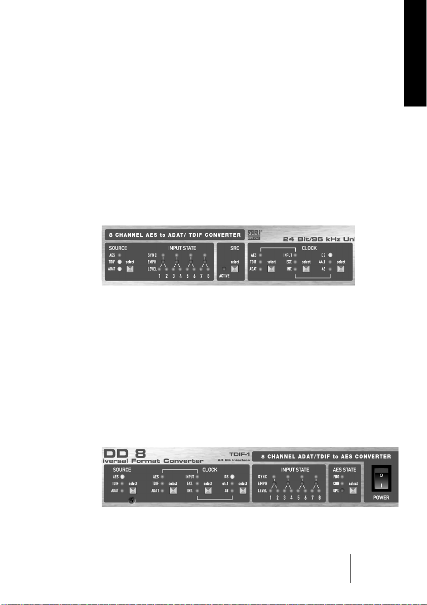
5.1 Tour de Nuendo DD 8
Join us for a small 'tour de Nuendo DD 8', starting on the left side at the
AES to ADAT/TDIF converter. Configuration starts with choosing the input signal (AES, ADAT or TDIF). The state of the digital input signal at the
4 XLR sockets is displayed by 16 LEDs. Shown are lock (pro XLR socket,
including SyncCheck), Emphasis and the level of the audio signal.
SRC activates a Hi-End 8-channel Sample Rate Converter. It is especially
useful when sources cannot be synced or the output signal shall have
another sampling frequency.
ENGLISH
Steinberg's intelligent clock control (ICC) offers extensive and professional means that are not easily met. To start with, the clock source can
be set to Internal (crystal), External (BNC word clock) and Input, while
Input lets you select between AES, ADAT or TDIF. The INT(ernal) clock
rates are 44.1 and 48kHz, and 88.2 and 96kHz after activating the DS
mode. After activating SRC, any AES signal from 32 to 96kHz can be
converted to 44.1, 48, 88.2 or 96kHz. Lock state and clock synchronicity
are being displayed by the state of each LED (flashing or constantly lit).
NUENDO DD 8
English – 11
Page 12

The ADAT/TDIF to AES section is layed out in a similar way. After choosing the input signal (AES, ADAT or TDIF), the clock source and the sampling rate, there is a field with 16 LEDs for displaying the output state.
An Emphasis bit at the TDIF input will be automatically set and indicated for the AES out. The lock state of the input signals is being displayed at the Input selector by flashing LEDs. The sync LEDs show the
synchronicity between both ADAT or TDIF inputs, as in double speed
mode (DS) 2 I/Os are active (4 channels each). The AES output signal
can also be set to Consumer subcode. The first output (channel 1/2) can
optionally be output optically (via TOSLINK) using the ADAT AUX port.
The unit always sends its output signal to ADAT and TDIF simultaneously. Additionally when operating at no higher than 48 kHz both
ADAT outputs and TDIF interfaces get the same signal. Thus the distribution capability is doubled to 2 x ADAT and 2 x TDIF. Thanks to the
possibility to freely select between inputs, all attached devices can
send signals to each other without the need to rearrange the cabling
between them.
NUENDO DD 8
English – 12
Page 13
6. The AES to ADAT/TDIF Converter
6.1 General
The Nuendo DD 8'S functional unit, which will be called 'left part' further on, is an 8-channel format converter from AES/EBU to ADAT/TDIF,
with the output signal being transmitted both at the ADAT and TDIF
ports in parallel. As long as the device is not working in DS mode (Double Speed), the output signal is even present at both ADAT and TDIF
ports (MAIN/AUX). Therefore the Nuendo DD 8 can pass on a 4 x 2
channel AES/EBU input signal to up to two ADAT and TDIF devices at
the same time (splitter 1 to 4). If AES is chosen as source in the right
part, there are the four AES/EBU outputs as well.
The four AES/EBU inputs process Double Speed (up to 96 kHz) and
Double Wire (up to 48 kHz) automatically. Excessive status displays
(Lock, SyncCheck, Emphasis, Level) help to avoid wrong configuration
and wrong clock setup.
A switchable high-end 8-channel sample rate converter can both convert the sample rate and decouple the AES/EBU inputs.
ENGLISH
6.2 Inputs
At the rear side of the
Nuendo DD 8 there are
four XLR sockets for the
AES/EBU inputs. Every
input is transformerbalanced and ground-
free. Channel status
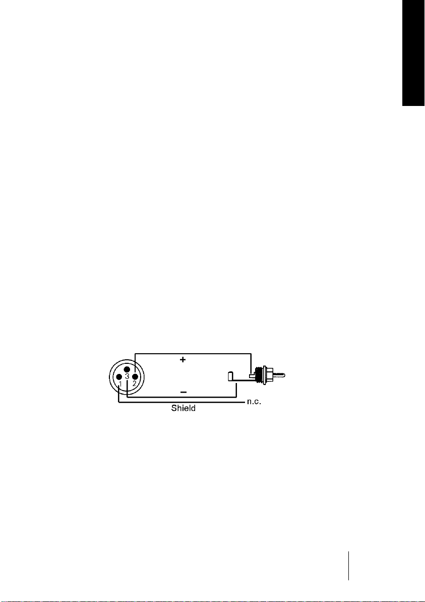
and copy protection are being ignored. Thanks to a highly sensitive input stage, also SPDIF signals can be processed using a simple cable
adapter (Phono/XLR).
To achieve this, pins 2 and 3 of an XLR plug are being connected to the
two contacts of a Phono plug. The ground shield of the cable is only
connected to pin 1 of the XLR plug.
NUENDO DD 8
English – 13
Page 14
The inputs can be used in any combination, e. g. it is sufficient to connect an input signal only to input 3. In slave mode, this input is automatically being used as clock source. If more than one signal is present,
the one furthest left is being used as clock source, i. e. the active input
with the lowest number.
The inputs are being copied to the 8 channel ADAT/TDIF formats in logical order:
AES/EBU Input 1 2 3 4
ADAT/TDIF MAIN+AUX 1/2 3/4 5/6 7/8
If an input sample rate higher than 56 kHz is detected at the AES/EBU
input, the DS LED lights up and the left part automatically switches to
DS mode, using the following channel distribution:
AES/EBU 1L 1R 2L 2R 3L 3R 4L 4R
ADAT/
TDIF
1/2
MAIN
3/4
MAIN
5/6
MAIN
7/8
MAIN
1/2
AUX
3/4
AUX
5/6
AUX
7/8
AUX
If a signal in Double Wire format is present at the input, technically no
special processing is activated. There is no need for processing, because the output signals will be in Sample Split format (S/MUX, Double
Line) right away.
6.3 Input State Display
The input state is displayed with 16 LEDs. Every input has its own LOCK
LED. However a missing or invalid input signal is indicated by slow
flashing of the SOURCE LED. As soon as a valid input signal is present
the four LOCK LEDs will react per input. If ADAT or TDIF are chosen as
input source (Copy Mode), all four LOCK and Emphasis LEDs show the
same information. In DS mode, both two and two LEDs show the state
of the MAIN (1/2) and the AUX (3/4) inputs.
NUENDO DD 8
English – 14
Page 15

If a valid input signal is applied, SyncCheck is automatically active.
When more than one input signal is present, the input with the lowest
number serves as reference. If the AES input is not chosen as clock
source, SyncCheck takes the chosen clock as reference and compares it
with the input clocks. Inputs which are not synchronous are shown by
quick flashing of the corresponding LOCK LED.
AES/EBU, S/PDIF and TDIF can contain an Emphasis information. Audio
signals with Emphasis have a strong high-frequency boost and thus require a high-frequency attenuation on playback. If one of the inputs
detects Emphasis, this information is being set at the TDIF output (and
being transmitted correctly to a DTRS machine). The alerting red colour
of the Emphasis LEDs has another reason:
❐
Emphasis is not available within the ADAT standard! This information is
thus neither passed on to the ADAT output, nor taken into account later
on for acoustic transmission!
Each channel's audio level is shown by a level LED. The green LED becomes active from -90 dBFS and above, a higher level yields brighter
light. Thus only one LED is necessary to see if there is an audio signal or
digital zero, only noise floor or a useful signal.
ENGLISH
6.4 Sample Rate Conversion
Each AES/EBU input has its own sample rate converter (SRC). An SRC allows for a conversion of the sampling rate in real-time. The 24 bit SRCs
used in the Nuendo DD 8 work virtually without loss, i. e. there are no
audible artefacts or noise signals. The SRC works so well that we could
recommend to leave it switched on all the time, and thus eliminate any
clock problem in the first place.
The Nuendo DD 8's SRC yields a maximum conversion ratio of 3:1 or 1:3.
96 kHz can be converted to any sample rate down to 32 kHz, 32 kHz to
any rate up to 96 kHz.
If the internal clock is being used, the SRC works as a perfect jitter killer.
But the Nuendo DD 8 allows for any source as clock reference. With
other settings than INT, the device is slave as usual and the jitter of the
output signal thus depending on the jitter of the clock source.
NUENDO DD 8
English – 15
Page 16

An SRC is not only being used for conversion of sample rates and jitter
suppression, it is especially useful for the so-called clock decoupling. By
means of an SRC, any device which can't be synchronized (CD-Player,
consumer DAT etc.) can be used within the system as if it was synchronizable. The SRC decouples any input clocks and sets the output clock
to the common reference (no matter which one), and thus allows for
bringing together various clock sources without any clicks or drop-outs.
Further information on sample rate conversion can be found in chapter
11, Technical Background.
6.5 Outputs ADAT Optical/TDIF
The Nuendo DD 8 provides two digital outputs, both in ADAT optical
and TDIF-1 format. In normal operation only the MAIN outputs are
used. When using more than the first 4 channels at activated DS (Double Speed), the AUX outputs also have to be used.
TDIF and ADAT optical outputs always operate simultaneously and
carry the same audio data. As long as DS isn't activated MAIN and AUX
also operate simultaneously and carry the same audio data. With this it
is possible to distribute the output signal to two devices of the same
format. When using all connectors the Nuendo DD 8 can feed up to 4
devices (2 x ADAT, 2 x TDIF).
The ADAT optical outputs of the Nuendo DD 8 are fully compatible to
all ADAT optical inputs. A usual TOSLINK cable is sufficient for connection.
ADAT Main
Interface for the first or only device receiving an ADAT signal from the
Nuendo DD 8. Carries the channels 1 to 8. When sending a Double
Speed signal, this port carries the channels 1 to 4.
ADAT AUX
Copy of the data at the MAIN output. When sending a Double Speed
signal, this port carries the channels 5 to 8. When AES STATE OPT is selected, ADAT AUX is used from the right part of the Nuendo DD 8 to
send channels 1/2 in SPDIF format
NUENDO DD 8
English – 16
Page 17

The TDIF-1 connectors of the Nuendo DD 8 are fully compatible to all
devices with such an interface, for example DA-38 and DA-88. The connection is done through a special TDIF cable, available at your local
dealer (Tascam part number PW-88D).
TDIF Main
Interface for the first or only device with a TDIF-1 interface. Carries the
channels 1 to 8. When transmitting a Double Speed signal, this port carries the channels 1 to 4.
TDIF AUX
Copy of the data at the MAIN interface. Carries the channels 5 to 8 in Bit
Split or Double Speed mode.
General tips for TDIF operation
TDIF and word clock
When the Nuendo DD 8 is slave, no additional word clock connection is
necessary. In case DA88 and/or DA38 are slave, the word clock output
of the Nuendo DD 8 has to be connected to the word clock input of the
first (master) recorder. When using more than one recorder, a special
sync cable (Tascam part number PW-88S) is needed.
ENGLISH
Emphasis
The AES/EBU and TDIF interface of the Nuendo DD 8 support Emphasis.
Please note that an Emphasis indication will not be stored or processed
on the sound when doing digital transfers between AES/EBU or TDIF
and ADAT, because the ADAT standard does not include Emphasis.
6.6 Input ADAT/TDIF (Copy Mode)
By means of the SOURCE button, ADAT and TDIF are available as signal
sources in the left part as well. Thus the Nuendo DD 8 turns into a
unique ADAT to TDIF and TDIF to ADAT converter, a digital patch bay
and signal distributor. These two source formats are notified with a yellow LED, after all they are the main inputs for the right part, i. e. the
ADAT/TDIF to AES/EBU converter, for which they are still available as inputs. Please refer to the block diagram on page 29.
NUENDO DD 8
English – 17
Page 18

In this operating mode, which is called
Copy Mode
due to its identical
source and destination format, the input signal can be forwarded to a
same format without having to change cables externally. The mathematical equation is
• (2 x ADAT In or 2 x TDIF In) to (2 x ADAT Out plus 2 x TDIF Out)
In other terms: The ADAT or TDIF input signal appears in parallel at the
ADAT and TDIF outputs. And the MAIN and AUX ports can be used to
pass through / distribute up to 16 channels at the same time.
In addition to the already described feature of signal distribution, the
Nuendo DD 8 thus also works as a patch bay, because the ADAT and
TDIF devices connected to the Nuendo DD 8 can exchange data directly among each other without re-connecting of cables. An ADAT optical or TDIF input signal is being output at two ADAT optical and two
TDIF ports at the same time.
Please take a look at the block diagram on page 29. It shows the whole
signal routing inside the Nuendo DD 8 in a clear way, also for this
Mode
.
❐
The sample rate converter is a part of the AES/EBU inputs, so when select-
Copy
ing ADAT/TDIF it is still only available to the AES inputs. The AES inputs
(including the SRC) can also be used by the right part of the Nuendo DD 8 if
necessary.
If the Copy Mode is active, the DS mode can be activated manually with
the button for the sampling frequency. There is a reason for this: normally, the 8 channel input signal of the ADAT or TDIF MAIN input is copied to both outputs MAIN/AUX (splitter). But if a Sample Split, S/MUX or
Double Wire signal is present at the ADAT or TDIF input, also the data of
the AUX input has to be passed on to the AUX output for full transmission of 8 channels. In other terms: 16 channels are being forwarded 1:1.
❐
In order to make use of all 16 TDIF and ADAT channels in Copy Mode, DS
has to be activated, even if it is only Single Speed signals.
The level display then works like in Sample Split operation. Two channels are being displayed on one LED (1+2, 3+4 etc.).
NUENDO DD 8
English – 18
Page 19

Emphasis
The AES/EBU and TDIF interface of the Nuendo DD 8 support Emphasis.
Please note that an Emphasis indication will not be stored or processed
on the sound when doing digital transfers between AES/EBU or TDIF
and ADAT, because the ADAT standard does not include Emphasis.
7. The ADAT/TDIF to AES/EBU Converter
7.1 General
The Nuendo DD 8's functional unit called 'right part' further on, is an 8channel format converter from ADAT/TDIF to AES/EBU.
ENGLISH
Because the
tain a coding, the Nuendo DD 8 cannot distinguish them from normal
(44.1/48 kHz) material. Whether the AES/EBU outputs are supposed to
work in Single (44.1/48 kHz) or Double Speed (88.2/96 kHz) has to be
set explicitly by the user. This happens in the clock section with the
sample frequency button, activating DS.
Complete status displays (Lock, SyncCheck, Emphasis, Level) help to
avoid wrong configuration and wrong clock setup.
Double Wire
and
Sample Split
(S/MUX) formats don't con-
7.2 Inputs
The Nuendo DD 8 provides two digital inputs, both in ADAT optical and
TDIF-1 format. The key SOURCE sets the desired input active.
In normal operation only the MAIN inputs are used. When using more
than the first 4 channels at activated DS (Double Speed), the AUX inputs also have to be used.
The input data is passed on to the four AES/EBU outputs in logical order:
ADAT/TDIF 1 2 3 4 5 6 7 8
AES/EBU 1L 1R 2L 2R 3L 3R 4L 4R
NUENDO DD 8
English – 19
Page 20

If the input data is encoded with Sample Split, S/MUX or Double Line,
the AES output has to be set to DS mode manually. Every input contains the information of only 4 channels, for full 8 channels MAIN
and
AUX have to be used. 16 input channels 44.1/48 kHz are being converted to 8 output channels 88.2/96 kHz. The channels are being distributed in the following manner:
ADAT/TDIF
MAIN+AUX
AES/EBU 1L 1R 2L 2R 3L 3R 4L 4R
1/2
MAIN
3/4
MAIN
5/6
MAIN
7/8
MAIN
1/2
AUX
3/4
AUX
5/6
AUX
7/8
AUX
The ADAT optical inputs of the Nuendo DD 8 are fully compatible with
all ADAT optical outputs. Steinberg's unsurpassed Bitclock PLL prevents clicks and drop outs even in extreme varipitch operation, and
guarantees a fast and low jitter lock to the digital input signal. A usual
TOSLINK cable is sufficient for connection.
ADAT Main
Interface for the first or only device sending an ADAT signal to the Nuendo DD 8. Carries the channels 1 to 8. When receiving a Double Speed
signal, this input carries the channels 1 to 4.
ADAT AUX
Interface for the second device sending a Double Speed signal to the
Nuendo DD 8. Carries the channels 5 to 8. Receives channels 9-16 in
Copy Mode.
The TDIF-1 connectors of the Nuendo DD 8 are fully compatible with all
devices offering such an interface, for example DA-38 and DA-88. A SDPLL ensures best playback sound quality and reliable operation. SyncCheck verifies synchronous operation when using both TDIF ports. The
connection is done through a special TDIF cable, available at your local
dealer (Tascam part number PW-88D).
TDIF Main
Interface for the first or only device with a TDIF-1 interface. Carries the
channels 1 to 8. When transmitting a Double Speed signal, this port carries the channels 1 to 4.
NUENDO DD 8
English – 20
Page 21

TDIF AUX
Carries the channels 5 to 8 in Double Speed mode. Transmission of
channels 9-16 in Copy Mode.
General tips for TDIF operation
TDIF and word clock
When the Nuendo DD 8 is slave, no additional word clock connection is
necessary. In case DA88 and/or DA38 are slave, the word clock output
of the Nuendo DD 8 has to be connected to the word clock input of the
first (master) recorder. When using more than one recorder, a special
sync cable (Tascam part number PW-88S) is needed.
7.3 Input State Display
The input state is being displayed by means of 16 LEDs. A missing or
invalid input signal is indicated by slow flashing of the SOURCE LED. In
case ADAT or TDIF are selected all four SYNC and Emphasis LEDs are
showing the same information. In DS mode both two and two LEDs
show the state of the MAIN (1/2) and the AUX (3/4) inputs.
ENGLISH
If MAIN and AUX are not synchronous to each other, the corresponding
input's SYNC LEDs will be quickly flashing. If the input is not chosen as
clock reference, SyncCheck takes the chosen clock (internal, external
etc.) as reference and compares it to the clocks of the inputs. Non synchronous inputs will be indicated by quick flashing of the corresponding SYNC LEDs.
If the TDIF input signal contains emphasis information, all four EMPHASIS
LEDs in the output state area will light up. The AES/EBU output channel
status will then be changed from 'no emphasis' to '50/15 µs' (emphasis).
Because this coding cannot be changed manually, and unfortunately
does not necessarily have to be correct in the source, we chose red LEDs
to give both a note and warning.
Each channel's audio level is shown by a level LED. The green LED becomes active from -90 dBFS and above, a higher level yields brighter
light. Thus only one LED is necessary to see if there is an audio signal or
digital zero, only noise floor or a useful signal.
NUENDO DD 8
English – 21
Page 22
7.4 Outputs AES/EBU
At the rear side of the Nuendo DD 8 there are four XLR sockets for the
AES/EBU outputs. Every output is transformer-balanced, ground-free
and compatible to all devices with AES/EBU port. Connection is accomplished using balanced cables with XLR plugs.
If AES STATE PRO (Professional) is chosen, the output level is almost 5V.
If CON (Consumer) is chosen, the output signal will have a channel status compatible to SPDIF. As far as we know, every SPDIF device should
be capable of handling an input signal of up to 5V instead of the usual
0.5V. Nevertheless the output level will be reduced to 2V when CON is
selected.
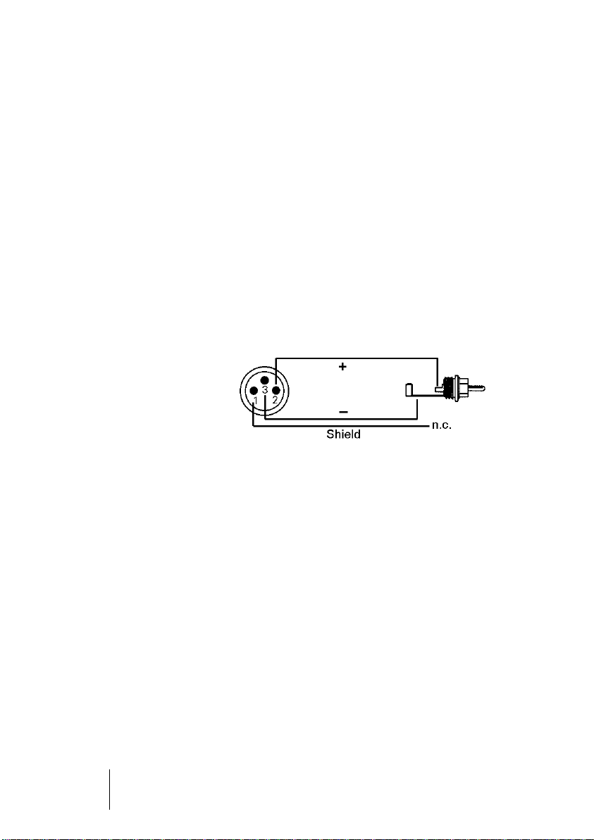
Connecting devices with coaxial SPDIF ports to the Nuendo DD 8 is accomplished with simple cable adapters (XLR/Phono).
To achieve this, pins 2
and 3 of an XLR plug are
being connected to the
two contacts of a Phono
plug. The ground shield
of the cable is only connected to pin 1 of the
XLR plug.
Additionally, there is the possibility of using the second ADAT output
as optical SPDIF output. If AES STATE OPT is chosen, the channels 1/2
will also be transmitted via ADAT AUX.
Digital signals in SPDIF or AES/EBU format contain a channel status
coding besides the audio data, which is being used for transmitting further information. The output signal coding of the Nuendo DD 8 has
been implemented according to AES3-1992 Amendment 4.
• 32 kHz, 44.1 kHz, 48 kHz, 64, kHz, 88.2 kHz, 96 kHz according to sample rate
• Audio use
• No Copyright, Copy permitted
• Format Consumer oder Professional
• Category General, Generation not indicated
• 2-Channel, No Emphasis oder 50/15 µs
• Aux Bits Audio use, 24 Bit
• Origin: Nuendo DD 8
NUENDO DD 8
English – 22
Page 23

❐
Note that most consumer-orientated equipment (with optical or phono
SPDIF inputs) will only accept signals in ‘Consumer’ format!
The status 'Professional' should always be active when sending data to
a device with AES/EBU input (when the XLR connectors are used).
7.5 Input AES/EBU (Copy Mode)
With the SOURCE button, AES/EBU can be chosen as the source for the
right part, in addition to ADAT or TDIF. The Nuendo DD 8 then turns
into a unique 8 channel AES/EBU to AES/EBU sample rate converter,
line buffer, signal refresher and signal distributor. This input format is
indicated by a yellow LED, after all it is the main input for the left part
(the AES/EBU to ADAT/TDIF converter), for which it is still available as
input. Please refer to the block diagram on page 29.
ENGLISH
In this operating mode, which is called
source and destination formats, the input signal can be forwarded to a
same format without having to change cables externally.
In addition to the already described feature of signal distribution, the
Nuendo DD 8 thus works as a patch bay, because the AES/EBU devices
connected to the Nuendo DD 8 can exchange data directly among
each other without re-connecting of cables.
Please take a look at the block diagram on page 29. It shows the whole
signal routing inside the Nuendo DD 8 in a clear way, also for this
Mode
.
Copy Mode
due to its identical
Notes on special functions
In the operating mode AES to AES, which is only available in the right
part, the Nuendo DD 8 has several special features. The right INPUT
STATE Display does then work exactly like the left one and does therefore display LOCK/SYNC and EMPHASIS for each AES input.
❐
If AES is chosen as source and only one AES input is supplied with a valid
signal, the Nuendo DD 8 switches to a distribution mode. The input signal
will then be copied to all outputs (splitter 1 to 4). Therefore all level LEDs
(instead of only two) will light up.
Copy
NUENDO DD 8
English – 23
Page 24

While in the left part an AES Double Speed signal (sample rate > 56 kHz)
is being indicated automatically by the DS LED, this is not the case in
the right part. If you are not sure about the input sampling frequency,
you can still check it in the left part (by switching to AES source for a
moment).
❐
The reason for the missing automatism is the ability to convert Double
Wire to Single Wire and Single Wire to Double Wire. This is controlled by
manual activation of the DS function.
• If an AES signal in Double Wire format is present (carrier 32 to 48 kHz) and DS is
activated, the data split into up to 8 channels is being converted into the original up to 4 channels Single Wire (64 to 96 kHz, output in Double Speed).
• This is also true for ADAT (S/MUX) and TDIF (Double Line). These signals can
also be converted to single wire double speed AES/EBU in the right part.
• If a single wire Double Speed AES signal (64 to 96 kHz) is present, the first 4
channels will be converted to 8 channels Double Wire (32 to 48 kHz) with DS
deactivated.
All those conversions are loss-less, the available samples will only be
put together or distributed between the channels.
In AES to AES mode the SRC is also available. Also placed on the left
side of the front panel, it then works for the right part of the device. This
is indicated by a quick alternating flashing of the SRC and the right AES
SOURCE LED. If the SRC is active, the conversion between Single Wire
and Double Wire as described above are not available. The DS function
only sets the output sample rate.
NUENDO DD 8
English – 24
Page 25

8. Clock Section
8.1 Clock Configuration
The Nuendo DD 8 has an almost identical clock section in the left and
right part, with professional capabilities that are hard to meet. The
unique ICC technology (Intelligent Clock Control) allows for a flexible
use of both functional units with internal clock (44.1 and 48 kHz, 88.2
and 96 kHz in DS mode), external word clock or the digital input signals.
All options are intelligently coupled and easily applicable and understandable, thanks to a clear display of the corresponding lock state.
As clock source, INTERNAL (crystal), EXTERNAL (BNC word clock) and
INPUT (the digital input signal AES/TDIF/ADAT) can be chosen. If the
clock signal is present, the corresponding LED will light constantly, if it
is not present, the LED will flash.
❐
If the SRC is active and AES is chosen as signal source in both parts, the
right part's clock LEDs will be inactive, because two different clock settings for one signal is not possible.
If AES is chosen as signal source in both parts, and the SRC is not active,
both clock sections remain active. By this it is avoided that the present
clock setting is lost for a short moment when stepping through the inputs on one side. Please note that in this case an identical left and right
clock setting should be selected. Nuendo DD 8 will help you detect
wrong settings as SyncCheck reliably indicates wrong or unequal settings.
ENGLISH
INPUT
As displayed on the front panel, the CLOCK SOURCE for the INPUT setting can be the AES, TDIF or ADAT input. This selection is independant
from the signal source. If the signal source is set to AES, the clock source
can still be ADAT, given that a valid ADAT signal is available. A missing
or invalid clock source signal is indicated by slow flashing of the corresponding LED.
NUENDO DD 8
English – 25
Page 26

EXT.
With EXTERNAL, the Nuendo DD 8's word clock input is used as clock reference. The LED will flash slowly, if the word clock is missing or unusable.
INT
For INTERNAL, 44.1 kHz or 48 kHz sampling rate is available. If DS is active in the left part, the data will be transmitted in Sample Split format
(S/MUX, Double Line). If DS is active in the right part, the output sample
rate doubles to 88.2 kHz or 96 kHz.
❐
For the INTERNAL clock setting it is mandatory that the clock rate of the
sources is synchronous to the Nuendo DD 8. Therefore the external device
has to be synchronized to the Nuendo DD 8's word clock out or AES/TDIF/
ADAT out.
The Nuendo DD 8 thus has to be master, all devices connected to it
slave (exception: SRC mode). In order to avoid clicks and drop outs in
this operating mode due to faulty or missing synchronicity, a special
process called SyncCheck compares the incoming data and the Nuendo DD 8's internal clock. Like LOCK, SYNC is indicated by flashing (error) or constantly lit (OK) LED. While LOCK is also indicated with the
source LEDs, SyncCheck steers the four SYNC LEDs. Besides, the flashing frequency is twice as high.
8.2 Lock, SyncCheck and SyncAlign
Digital signals consist of a carrier and the data. If a digital signal is applied to an input, the receiver has to synchronize to the carrier clock in
order to read the data correctly. To achieve this, the receiver has a PLL
(Phase Locked Loop). As soon as the receiver has locked to the exact
frequency of the incoming signal, it is locked. This
even with small changes of the frequency, because the PLL tracks the
receiver's frequency.
If an AES, TDIF or ADAT signal is applied to the Nuendo DD 8, the corresponding input LED stops flashing. The device indicates LOCK, i. e. a
valid input signal.
NUENDO DD 8
English – 26
Lock
state remains
Page 27

Unfortunately, LOCK does not necessarily mean that the received signal is correct with respect to the clock processing the read out of the
embedded data. Example [1]: The Nuendo DD 8 is set to 44.1 kHz internal and a CD-Player is connected to input AES1. The INPUT LED will
show LOCK immediately, but the CD-Player's sample rate is generated
internally, and thus slightly higher or lower than the Nuendo DD 8's internal sample rate. Result: When reading out the data, there will frequently be read errors that cause clicks and drop outs.
Also when using multiple inputs, a simple LOCK is not sufficient. The
above described problem can be solved elegantly by setting the Nuendo DD 8 from INT to INPUT (its internal clock will then be the clock
delivered by the CD-Player). But if you now connect a DAT recorder as a
second source, there will again be a slight difference in the sample rate,
and therefore clicks and drop outs [2]. Another example could be connecting to ADAT machines which are not synchronous to each other
due to wrong clock setup [3].
In order to display those problems optically at the device, the Nuendo
DD 8 contains SyncCheck®. It checks all clocks used for synchronicity. If
they are not synchronous to each other (i. e. absolutely identical), the
SYNC LED of the asynchronous input flashes. In example 1 it would
have been obvious at once that the SOURCE AES LED was constantly lit
when connecting the CD-Player, but that the SYNC LED was flashing. In
example 2, all LEDs would be constantly lit except the SYNC LED of the
input used by the DAT. In example 3, two LEDs are constantly lit, while
two others are flashing.
ENGLISH
In practice, SyncCheck allows for a quick overview of the correct configuration of all digital devices. So one of the most difficult and errorprone topics of the digital studio world finally becomes easy to handle.
A special problem occurs with devices offering several AES or SPDIF inputs. While with ADAT and TDIF all 8 channels share the same clock
base, with AES there are several completely independant receivers with
own PLLs and data buffers. Therefore there can be a random error of ±
1 sample difference between the stereo pairs. The Nuendo DD 8's exclusive SyncAlign® technology avoids this effect and guarantees sample synchronicity among all 4 stereo channels.
NUENDO DD 8
English – 27
Page 28

Unfortunately, this method does not work automatically when the SRC
is active. For this reason, the SRC must be switched on and off once
when all AES sources have been connected and stable SYNC is displayed. All four SRCs do now operate in sync with sample accuracy.
(This is only relevant, if you wish to convert a multi channel signal from
one source only – e.g. from a mixer or a tape recorder – using SRC.
8.3 Word Clock Input and Output
Input
The Nuendo DD 8's word clock input is available to both the left and
the right part. It is active, when EXT is chosen in the clock section. The
signal at the BNC input can be single or double speed, the Nuendo DD
8 automatically adapts to it. As soon as a valid signal is detected, the
EXT LED is constantly lit, otherwise it is flashing.
Thanks to the
Signal adaptation Circuit
, the word clock input still works
correctly even with heavily mis-shaped, dc-prone, too small or overshoot-prone signals. Thanks to automatic signal centering, 300 mV
(0.3V) input level are sufficient in principle. An additional hysteresis reduces sensitivity to 1.2 V, so that over- and undershoots and high-frequency disturbances don't cause a wrong trigger.
The Nuendo DD 8's input is designed with high resistance in order to
yield maximum flexibility for the user. If correct termination is required,
a 75 Ohm termination resistor is necessary (see
nation
).
11.2 Cabling and Termi-
Output
The word clock output is constantly active and basically delivers the
sample rate of the left part as word clock signal. As long as it is working
with internal clock, the output word clock is especially jitter-free (< 1
ns). The device can even be used as a central word clock generator (except the limitation of only one output). In slave mode (EXT/INPUT), the
amount of jitter is depending on the input signal.
A word clock signal fed to the Nuendo DD 8 can even be passed
through via the word clock output, because the output signal is phase
locked to the input signal (0˚). Thus the usual T-adaptor at the input is
not needed and the Nuendo DD 8 works as a signal refresher. This ap-
NUENDO DD 8
English – 28
Page 29

plication is even more interesting, because the exceptional input of the
Nuendo DD 8 (1 Vss sensitivity instead of the usual 2.5 Vss, dc cut, Signal Adaptation Circuit) guarantees a secure function also with critical
word clock signals.
❐
The Nuendo DD 8's word clock output is derived from the left part, because the TDIF ports need a fixed word clock reference.
For this reason, the word clock signal derived from AES, TDIF and ADAT
has a phase shift of 90˚ at the output. This has no effect when being
used with AES or ADAT, because these formats don't require a certain
relation to the word clock signal.
❐
The wordclock output as well as all ADAT and TDIF ports always operates
in Single Speed mode only. At 96 kHz, the word clock output will therefore
be a 48 kHz signal.
Thanks to a low impedance, but short circuit proof output, the Nuendo
DD 8 delivers 4 Vss to 75 Ohms. For wrong termination with 2 x 75
Ohms (37.5 Ohms), there are still 3.2 Vss at the output.
ENGLISH
NUENDO DD 8
English – 29
Page 30

9. Word Clock
9.1 Operation and Technical Background
In the analogue domain one can connect any device to another device, a
synchronization is not necessary. Digital audio is different. Correct interpretation of digital audio data is dependent upon a definite sample frequency. Signals can only be correctly processed or transferred between
devices if these all share the same clock, otherwise digital signals are misinterpreted, causing distortion, clicks/crackle and even dropouts.
AES/EBU, SPDIF and ADAT optical are self-clocking (seen from a nontechnical view TDIF also, as word clock is embedded into the TDIF cable), so an additional line for word clock could be considered redundant. In practice however, using several devices at the same time can
cause problems. For example, if devices are connected in a loop without there being a defined ‘master’ device, self-clocking may break
down. Besides, the clocks of all devices must be synchronized from a
single source. Devices without S/PDIF inputs (typically playback devices such as CD players) cannot be synchronized via self-clocking. Finally there are 'problematic' devices, which are nearly un-usable
without a word clock attached.
In digital studios, synchronization requirements can be met by connecting all devices to a central sync source. For instance, the master device could be a mixing desk, sending a reference signal - word clock - to
all other devices. However, this will only work if all the other devices
have word clock or sync inputs (e.g. some professional CD players), allowing them to run as slaves. This being the case, all devices will receive the same clock signal, so there is no fundamental reason for sync
problems when they are connected together.
But word clock is not only the 'great problem solver', it also has some
disadvantages. The word clock is based on a fraction of the really
needed clock. For example SPDIF: 44.1 kHz word clock (a simple square
wave signal) has to be multiplied by 128 or 256. This signal then replaces the one from the quartz crystal. Because of the high multiplication factor the reconstructed clock will have great deviations called
jitter. The jitter caused by word clock is typically 15 times higher as
when using a quartz based clock.
NUENDO DD 8
English – 30
Page 31

ENGLISH
• As long as it does not cause functional problems, jitter is only affecting AD- and
DA-conversion. For completely digital devices like the Nuendo DD 8 jitter is virtually meaningless because the data remains unaltered even with high jitter.
The end of these problems should have been the so called Superclock,
which uses 256 times the word clock frequency. The PLL for multiplying
is no longer needed, and the clock can be used directly. But in practise
Superclock proved to be much more critical than word clock. A square
wave signal of 11 MHz distributed to several devices - this simply
means to fight with high-frequency technology. Reflections, cable
quality, capacitive loads - at 44.1 kHz these factors may be ignored, at
11 MHz they are the end of the clock network. Superclock was, however, not widely accepted. This non-standard procedure is therefore
not built-into the Nuendo DD 8.
The usage of word clock with ADAT optical is critical too. The Nuendo
DD 8 always uses a Bitclock PLL, no matter if the clock reference is word
clock or ADAT. Thanks to its very fine resolution this exceptional circuit
is able to follow the complete vari-speed range of the ADAT recorder
without losing a sample. Mayn other devices use a much coarser word
clock PLL to track the ADAT input. When changing the sample rate
(speed) fast, some bits are already sampled invalidly before the frequency is corrected. Drop outs and crackling will be the audible result.
So as long as you are working with the Nuendo DD 8 - no problem.
Working with devices of other manufacturers you may experience drop
outs when the sample rate changes only slightly.
The TDIF format is especially critical with respect to word clock. We
have mentioned this in different places of this manual:
When the Nuendo DD 8 is slave no additional word clock connection is
necessary. In case DA88 and/or DA38 are slave the word clock output of
the Nuendo DD 8 has to be connected to the word clock input of the
first (master) recorder. When using more than one recorder a special
sync cable (Tascam part number PW-88S) is needed.
What you do not need to know: the Nuendo DD 8 takes care of the first
DTRS machine's properties, the DA-88, and it can be used together with
this device without further settings.
NUENDO DD 8
English – 31
Page 32

9.2 Cabling and Termination
Word clock signals are usually distributed in the form of a network, split
with BNC T-adapters and terminated with resistors. We recommend using off-the-shelf BNC cables to connect all devices, as this type of cable
is used for most computer networks. You will find all the necessary
components (T-adapters, terminators, cables) in most electronics and/
or computer stores.
Ideally, the word clock signal is a 5 Volt square wave with the frequency
of the sample rate, of which the harmonics go up to far above 500 kHz.
To avoid voltage loss and reflections, both the cable itself and the terminating resistor at then end of the chain should have an impedance of
75 Ohm. If the voltage is too low, synchronization will fail. High-frequency reflection effects can cause both jitter and sync failure.
Unfortunately there are still many devices on the market, even newer
digital mixing consoles, which are supplied with a word clock output
that can only be called unsatisfactory. If the output breaks down to 3
Volts when terminating with 75 Ohms, you have to take into account
that a device, of which the input only works from 2.8 Volts and above,
does not function correctly already after 3 meters of cable. So it is not
astonishing that because of the higher voltage, word clock networks
are in some cases more stable and reliable if cables are not terminated
at all.
Ideally all outputs of word clock delivering devices are designed with
very low impedance, but all word clock inputs with high impedance, in
order to not weaken the signal on the chain. But there are also negative
examples, when the 75 Ohms are built into the device and cannot be
switched off. In this case the network load is often 2 x 75 Ohms, and the
user is forced to buy a special word clock distributor. Note that such a
device is generally recommended for larger studios.
Also, 75 Ohm cable is almost impossible to find these days. 50 Ohm cable is standard - this will also work as long as the termination resistors
are 75 Ohm.
NUENDO DD 8
English – 32
Page 33

The Nuendo DD 8's word clock input is a high-impedance type ensuring maximum flexibility, and is therefore not terminated. If normal termination is necessary (e.g. because Nuendo DD 8 is the last device in
the chain), simply connect a T-adapter to its BNC input jack, connect
the cable supplying the word clock signal to one arm of the T-adapter
and terminate the other with a 75 Ohm resistor (as a short BNC plug).
In case the Nuendo DD 8 resides within a chain of devices receiving word
clock, plug a T-adapter into its BNC input jack, and the cable supplying
the word clock signal to one end of the adapter (as above), but connect
the free end to the next device in the chain via a further BNC cable. The
last device in the chain should be terminated using another T-adapter
and a terminator plug as described in the previous paragraph.
ENGLISH
NUENDO DD 8
English – 33
Page 34

10. Conversion Modes and Notes
In this chapter the Nuendo DD 8's conversion functions are listed functionally and separated for left and right part. At first the functions of the
left part are described. From chapter 10.7 on the right part follows.
Chapter 10.12 describes a special case where both parts are being operated together.
'ADAT || TDIF' means that the output signal is present at the ADAT and
TDIF outputs in parallel, i. e. at the same time. 'ADAT / TDIF' means that
either ADAT or TDIF can be used as input signal.
Left Part
10.1 – 8-channel AES to ADAT || TDIF Converter (96 kHz)
SOURCE: AES
Note: For sample rates higher than 56 kHz the DS LED lights up, and the
outputs automatically work in Sample Split / Double Line mode. Each
output port (MAIN/AUX) then carries 4 channels.
10.2 – 8-channel AES to 2 x ADAT || 2 x TDIF Splitter (48 kHz)
SOURCE: AES
Note: For sample rates below 56 kHz the MAIN and AUX outputs will
carry the same data. Thus two outputs each can be used for ADAT and
TDIF (splitter).
10.3 – 2-channel AES to 8-hannel TDIF || ADAT Splitter (96 kHz)
SOURCE: AES
Note: If only one AES input is being fed, the Nuendo DD 8 automatically
switches to a distribution mode. The input signal will then be copied to
all stereo output channels (splitter 1 to 4). Because MAIN and AUX carry
the same data, the input signal is split to eight stereo pairs for ADAT
and eight stereo pairs for TDIF. If AES is selected in the right part, the
stereo input signal will also appear at all four AES outputs.
For sample rates above 56 kHz the DS LED lights up, and the outputs
operate in Sample Split / Double Line mode. Every output (MAIN/AUX)
then carries 4 channels.
NUENDO DD 8
English – 34
Page 35

10.4 – 8-channel ADAT/TDIF to 2 x ADAT || 2 x TDIF Splitter (48 k mHz)
SOURCE: ADAT or TDIF
Note: For sample rates below 56 kHz the MAIN and AUX outputs will
carry the same data. Thus two outputs each for ADAT and TDIF can be
used (splitter).
10.5 – 16-channel ADAT/TDIF to ADAT || TDIF Converter (48 kHz)
SOURCE: ADAT or TDIF
Note: If DS is activated manually at sample rates below 56 kHz, the
MAIN and AUX outputs will not carry the same data any longer. Instead
the data from the MAIN and AUX inputs will be passed 1:1 to the MAIN/
AUX outputs. It is then possible to transmit and convert 16 channels at
the same time.
10.6 – 8-channel ADAT/TDIF to ADAT || TDIF Converter (96 kHz)
Note: Identical to 10.5
Signals in Sample Split (S/MUX) or Double Line format require 16 chan-
nels for the transmission of 8 channels Double Speed. Therefore the
data has to be passed on 1:1.
ENGLISH
Right Part
10.7 – 8-channel ADAT/TDIF to AES Converter (96 kHz)
SOURCE: ADAT or TDIF
Note: If the input data is encoded in Sample Split (S/MUX) or Double Line
format, the DS function has to be activated manually in order to have the
AES outputs transmit 8 channels in Double Speed / Single Wire.
10.8 – 8-channel AES to AES Sample Rate Converter (96 kHz)
SOURCE: AES
Note: After activating the sample rate converter (SRC) and using the in-
ternal clock (INT), the desired output sample rate can be chosen with
the clock button.
NUENDO DD 8
English – 35
Page 36

10.9 – 2-channel AES to 8-channel AES Splitter (96 kHz)
SOURCE: AES
Note: If only one AES input is being fed with a valid signal, the Nuendo
DD 8 automatically switches to a distribution mode. The input signal
will be copied to all stereo output channels (splitter 1 to 4), i. e. it will
appear at all four AES outputs. If AES is selected as input source for the
left part, this also holds true for the ADAT/TDIF outputs (see 10.3).
10.10 – 4-channel AES Double Wire to AES Single Wire Converter (96 kHz)
SOURCE: AES
Note: If the input signal is present in Double Wire format, DS has to be
activated manually in order to have the AES outputs transmit 4 channels of Double Speed / Single Wire data.
10.11 – 4-channel AES Single Wire to AES Double Wire Converter (96 kHz)
SOURCE: AES
Note: When DS is not active and the input signal is in Single Wire Dou-
ble Speed format, the data will be converted to Double Wire Single
Speed,. Because only 8 physical output channels are available, there
will only be 4 audio channels effectively. The inputs 5 - 8 cannot be
transmitted via AES.
10.12 – 8-channel ADAT/TDIF to ADAT || TDIF Sample Rate Converter
(96 kHz)
The Nuendo DD 8's sample rate conversion is a fixed component of the
AES inputs. However, because the device contains two independant
format converters, also 8 channels ADAT or TDIF can be changed in
sample rate and clock-decoupled!
To achieve this, connect the four AES outputs with the four AES inputs
(loop-back cabling), i. e. 1 with 1, 2 with 2, 3 with 3 and 4 with 4.
Right part
SOURCE: ADAT or TDIF
NUENDO DD 8
English – 36
Page 37

Left part
SOURCE: AES
SRC: Active
At first ADAT/TDIF is converted to AES in the right part. The Nuendo DD
8's AES outputs are connected to the AES inputs with XLR cables and
are being converted back to ADAT||TDIF in the left part. Now the SRC
can also be activated.
ENGLISH
NUENDO DD 8
English – 37
Page 38

11. Technical Background
11.1 DS - Double Speed
When activating the Double Speed mode, the Nuendo DD 8 operates at
double sample rate. The internal clock 44.1 kHz turns to 88.2 kHz, 48
kHz to 96 kHz. The internal resolution is still 24 bit.
Sample rates above 48 kHz were not always taken for granted, and are
still not widely used because of the CD format (44.1 kHz) dominating
everything. Before 1998 there were no receiver/transmitter circuits
available that could receive or transmit more than 48 kHz. Therefore a
work-around was used: instead of two channels, one AES line only carries one channel, of which the odd and even samples are being distributed to the former left and right channels. By this, you get the double
amount of data, i. e. also double sample rate. In order to transmit a
stereo signal two AES/EBU ports are necessary then.
This transmission mode is being called Double Wire in the professional
studio world, and is also known as S/MUX in connection with the ADAT
format. The DTRS recorder DA-98HR by Tascam also uses this technique, which is called Dual Line here.
Not before February 1998, Crystal shipped the first 'single wire' receiver/
transmitters that could also work with double sample rate. It was then
possible to transmit two channels of 96 kHz data via one AES/EBU port.
But Double Wire is still far from being dead. On one hand, there are still
many devices which can't handle more than 48 kHz, e. g. digital tape recorders. But also other common interfaces like ADAT or TDIF are still using this technique.
Because the ADAT interface does not allow for sampling frequencies
above 48 kHz (a limitation of the interface hardware), the Nuendo DD 8
automatically uses a technique called Sample Split in DS mode. One
channel's data is distributed to two channels according to the following table:
Original 1 2 3 4 5 6 7 8
DS Signal
Port
NUENDO DD 8
English – 38
1/2
MAIN
3/4
MAIN
5/6
MAIN
7/8
MAIN
1/2
AUX
3/4
AUX
5/6
AUX
7/8
AUX
Page 39

As the transmission of double rate signals is done at standard sample
rate (Single Speed) the word clock output still delivers 44.1 kHz or 48 kHz.
❐
The wordclock output as well as all ADAT and TDIF ports always operates
in Single Speed mode only. At 96 kHz, the word clock output will therefore
be a 48 kHz signal.
The TDIF interface of the Nuendo DD 8 also supports the 'Double Wire'
technique. This allows a recording with up to 96 kHz at halfed track
numbers with every (!) DTRS device.
Note: The ideal combination is an Nuendo DD 8 together with the digital I/O card Nuendo 96/52). This card has Sample Split implemented in
hardware. This combination offers 4 AES/EBU I/Os, with 2 channels 24
bit/96 kHz each, using PC or Mac.
11.2 AES/EBU - SPDIF
The most important electrical properties of 'AES' and 'SPDIF' can be
seen in the below table. AES/EBU is the professional balanced connection using XLR plugs. The standard is being set by the Audio Engineering
Society based on the AES3-1992. For the 'home user', SONY and Philips
have omitted the balanced connection and use either Phono plugs or
optical cables (TOSLINK). The format called S/P-DIF (SONY/Philips Digital Interface) is described by IEC 60958.
ENGLISH
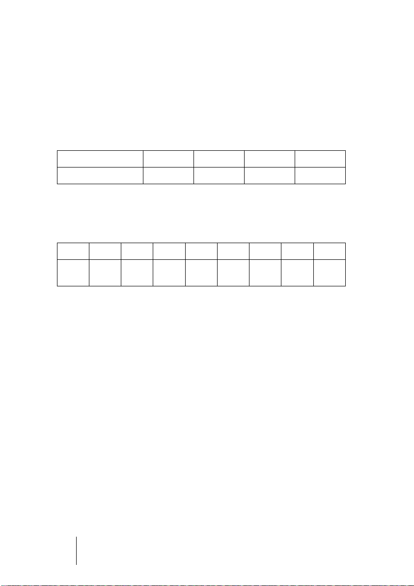
Type AES3-1992 IEC 60958
Connection XLR RCA / Optical
Mode Balanced Un-balanced
Impedance 110 Ohm 75 Ohm
Level 0.2 V up to 5 Vss 0.2 V up to 0.5 Vss
Clock accuracy not specified I: ± 50ppm
II: 0,1%
III: Variable Pitch
Jitter < 0.025 UI (4.4 ns @ 44.1 kHz) not specified
NUENDO DD 8
English – 39
Page 40

Besides the electrical differences, both formats also have a slightly different setup. The two formats are principally compatible, because the audio
information is stored in the same place in the data stream. However,
there are blocks of additional information, which are different for both
standards. In the table, the meaning of the first byte (#0) is shown for
both formats. Already in the first bit there is the decision whether the following bits should be read as Professional or Consumer information.
Byte Mode Bit 0 1 2 3 4 5 6 7
0 Pro P/C Audio? Emphasis Locked Sample Freq.
0 Con P/C Audio? Copy Emphasis Mode
As can be seen, the meaning of the following bits differs quite substantially in both formats. If a device like a common DAT recorder only has
an SPDIF input, it usually understands only this format. In most cases, it
will switch off when being fed Professional-coded data. The table
shows that a Professional-coded signal would lead to malfunctions for
copy prohibition and emphasis, if being read as Consumer-coded data.
This actually happened in former times, but today it is not more than an
artificial functional restriction.
Nowadays, many devices with SPDIF input can handle Professional
subcode. Devices with AES3 input almost always accept Consumer SPDIF (passive cable adapter necessary).
11.3 Clock De-coupling using the SRC
Master-slave problems occur at the latest with the use of a digital
mixer. For 'normal' use of CD-Player, DAT and harddisk recording, the
tasks are clearly defined. The device playing back is the master in each
case, the recording device the slave. The CD-Player delivers the clock
and the DAT synchronizes to it.
When working with a digital mixer, the CD-Player would be the master
and the mixer the slave. This model breaks down with a single stroke, if
a DAT is also being connected, which is not recording, but also playing
back. Every digital device can only synchronize to one source, the audio
data of the other sources is processed with errors due to missing synchronization. Clicks and drop outs are the consequence.
NUENDO DD 8
English – 40
Page 41

Normally, the mixing console works as master and delivers a reference
signal (word clock) to all other devices. But this is only possile, if the
other devices have a sync input, i. e. are capable of being slaved. In a
studio with digital tape machine, digital effects and harddisk recording,
common CD-Players and DATs cannot be connected to the mix section
of the console, simply because they cannot be synchronized.
This is no problem, if a sample rate converter is being used. It synchronizes any input signal to the desired sampling rate, re. the desired clock
reference.
By this, any device can be connected via the Nuendo DD 8 to any other
device in a studio with a central clock, independant from its original capabilities. Instead of the CD-Player or the DAT, the Nuendo DD 8 is the
slave now.
11.4 The SRC as Signal Conditioner
DAT tapes often show little formatting errors between the various recorded takes. There can also be tiny snippets with other sample rates
between the recordings. An SRC converts this patch-work reliably into
a continuous permanently valid data stream with a fixed sample rate.
Even if there are unformatted spots on the tape, or the DAT is being
stopped or switched off, the Nuendo DD 8 delivers a constant signal
(which does of course not contain audio information in this case).
ENGLISH
The use as supplier of an uninterrupted data stream is also helpful for
applications, that would otherwise suffer from functional errors or automatic switch-off of devices. Thanks to the SRC, the Nuendo DD 8 always delivers a constant output clock, no matter if the inputs are not
being used at the moment, are just being connected or have been used
all the time.
NUENDO DD 8
English – 41
Page 42

12. Controls and Connectors
Front Left Part
Clock Section
Signal source
AES
TDIF
ADAT
Front Right Part
Signal source
AES
TDIF
ADAT
Rear
Status display
Lock of inputs
Emphasis
Level
indication
Clock source
AES
TDIF
ADAT
Sample
Rate
Converter
Clock Section
Clock source
Input
External
(Word clock)
Internal
Clock source
AES
TDIF
ADAT
Internal clock
44.1 / 48 kHz
DS active:
88.2 / 96 kHz
Clock source
Input
External
(Word clock)
Internal
Status display
Lock of outputs
Emphasis
Level indication
InputsOutputsPower
Internal clock
44.1 / 48 kHz
DS active:
88.2 / 96 kHz
Status AES output
Professional
Consumer
Optical output
NUENDO DD 8
English – 42
Page 43

13. Connector Pinouts
D-Sub TDIF-1
The 25 pin D-sub connectors are wired according to TDIF-1, version 1.1:
ENGLISH
Signal Out
1/2
D-sub 1 2 3 4 5 18 6 19
Signal In
FS1
D-sub 20 8 21 9 10 11 12 13
Out
3/4
FS0InEMPHInLRCKIn7/8
Out
5/6
In
Out
7/8
Out
LRCK
Out
EMPH
In
5/6
Out
FS0
In
3/4
Out
FS1
In
1/2
GND is connected to pins 7, 14, 15, 16, 17, 22, 23, 24, 25.
AES/EBU
The XLR connectors are wired according to AES3-1992:
1 = GND (shield)
2 = Signal
3 = Signal
AES/EBU and SPDIF are biphase modulated signals, therefore polarity
doesn't matter. Pins 2 and 3 are neither hot nor cold, they carry the
same signal. But as AES3 uses a balanced transmission they are inverted in polarity.
NUENDO DD 8
English – 43
Page 44

14. Block Diagram
This is a block diagram of the Nuendo DD 8. It shows a functional overview of the device in order to help with questions regarding functions
and routing. It has been made simpler in some points and does not
show all possible functions in order to remain understandable and
overseeable. So, for instance the function of the optical SPDIF output is
missing.
NUENDO DD 8
English – 44
Page 45

15. Warranty
Before shipping, each Nuendo DD 8 is tested in a complete test sequence. Using only the best hi-grade components allows us to offer
two years of warranty. The copy of the sales receipt or the Bill of Sale is
your warranty legitimation.
In case of any error or defect please contact your local dealer. The warranty does not cover damage due to abuse, incorrect installation or incorrect handling.
Steinberg Media Technologies AG’s liability is limited to the repair or the replacement of the product, and does in no way include the liability for incidental or consequential damages resulting from using the Nuendo DD 8.
16. Appendix
Steinberg news and further information on our products can be found
on our website: http://www.Steinberg.net
Distributor:
Steinberg Media Technologies AG
Manufacturer:
IMM Elektronik GmbH, Leipziger Str. 27, D-09648 Mittweida
ENGLISH
Trademarks
All trademarks and registered trademarks belong to their respective
owners. RME, SyncAlign, DIGI96, Hammerfall and SyncCheck are registered trademarks of RME Intelligent Audio Solutions. Intelligent Clock
Control (ICC) is a trademark of RME Intelligent Audio Solutions. Alesis
and ADAT are registered trademarks of Alesis Corp. ADAT optical is a
trademark of Alesis Corp. TDIF is a trademark of TEAC Corp. S/MUX is
copyright Sonorus. WaveLab, Nuendo, Nuendo 8 I/O 96k and Nuendo
DD 8 are registered trademarks of Steinberg Media Technologies AG.
Copyright Matthias Carstens, 09/2001. Version 1.0
All entries in this User Guide have been thoroughly checked, however no guarantee
for correctness can be given. RME cannot be held responsible for any misleading or
incorrect information provided throughout this manual. Lending or copying any part
or the complete manual or its contents as well as the software belonging to it is only
possible with the written permission from RME. RME reserves the right to change
specifications at any time without notice.
NUENDO DD 8
English – 45
Page 46

CE
This device has been tested and found to comply with the limits of the
European Council Directive on the approximation of the laws of the
member states relating to electromagnetic compatibility (EMVG) according to EN 55022 class B and EN50082-1.
FCC Compliance Statement
Certified to comply with the limits for a Class B computing device according to subpart J or part 15 of FCC rules. See instructions if interference to radio reception is suspected.
FCC Warning
This equipment has been tested and found to comply with the limits
for a Class B digital device, pursuant to part 15 of the FCC rules. These
limits are designed to provide reasonable protection against harmful
interference in a residential installation.
This device complies with part 15 of FCC rules. Operation is subject to
the following two conditions:
1. This device may not cause harmful interference.
2. This device must accept any interference received, including interference
that may cause undesired operation.
However, there is no guarantee that interference will not occur in a particular installation. If this equipment does cause harmful interference
to radio or television reception, which can be determined by turning
the equipment off and on, the user is encouraged to try to correct the
interference by one or more of the following measures:
• Reorient or relocate the receiving antenna
• Increase the separation between the equipment and receiver
• Connect the equipment into an outlet on a circuit different from that to which
the receiver is connected.
• Consult the dealer or an experienced radio/TV technician for help.
In order for an installation of this product to maintain compliance with
the limits for a Class B device, shielded cables must be used for the connection of any devices external to this product.
NUENDO DD 8
English – 46
Page 47

1. Einleitung
Mit dem Nuendo DD 8 steht Ihnen ein geradezu unglaublich vielseitiges Digital-Interface zur Verfügung. Was zunächst wie ein einfacher
AES/TDIF/ADAT Formatwandler aussieht, entpuppt sich bei näherer Betrachtung als der Problemlöser schlechthin. Vom kleinen Projektstudio
bis zu Rundfunk und Fernsehen ist der Universal Format Converter die
perfekte Schnittstelle zwischen den heute gebräuchlichsten Formaten.
Der Nuendo DD 8 beinhaltet ausgefeilte Schaltungstechnologie und
modernste integrierte Schaltkreise, bei vollen 8 Kanälen in 24 Bit und 96
kHz. Der Nuendo DD 8 ist ein einmalig leistungsfähiges und hochqualitatives Gerät, welches Sie auch in vielen Jahren noch begeistern wird.
2. Lieferumfang
Bitte überzeugen Sie sich vom vollständigen Lieferumfang des Nuendo
DD 8:
• Gerät Nuendo DD 8
• Bedienungsanleitung
• Netzkabel
• 2 x 2 m optisches Kabel (TOSLINK)
DEUTSCH DEUTSCH
3. Kurzbeschreibung und Eigenschaften
Der Nuendo DD 8 besteht aus zwei bis zu 16-kanaligen digitalen Formatwandlern in Referenz-Qualität, in einem Standard 19" Gehäuse mit
1 HE Höhe. Das kompakte Gerät verfügt über zahlreiche außergewöhn-
liche Merkmale, wie Intelligent Clock Control (ICC), SyncCheck®, SyncAlign®, Bit-clock PLL, Patchbay Funktionalität und aktive Jitter-Unterdrückung per SD-PLL. Zuschaltbare Hi-End Sample Rate Converter (SRC)
erlauben sowohl eine Sampleratenkonvertierung in höchster Qualität
als auch eine Clock-Entkopplung aller AES/EBU Eingänge.
Alle digitalen Schnittstellen des Nuendo DD 8 unterstützen 96 kHz/24
Bit. Da ADAT optical und TDIF üblicherweise auf 48 kHz begrenzt sind,
werden im DS-Betrieb (Double Speed) zwei Kanäle benutzt um die Daten eines Kanales zu übertragen. Das dabei eingesetzte Sample Split-
NUENDO DD 8
Deutsch – 47
Page 48

Verfahren ist kompatibel zu S/MUX und Double Wire, und auch in Steinbergs Nuendo 96/52 implementiert. Damit stellt der Nuendo DD 8
auch ein ideales AES/EBU-Frontend für diese Interface-Karten auf der
Mac- und PC-Plattform dar.
Die Formatwandlung zwischen AES/EBU und ADAT/TDIF ist in beide
Richtungen gleichzeitig, dabei vollkommen unabhängig, aber auch intelligent gekoppelt möglich. Über verschiedenfarbige Leuchtdioden
wird der aktuelle Zustand der ein- und ausgehenden Signale sowie der
im Gerät stattfindenden Vorgänge übersichtlich angezeigt.
Die einmalige Intelligent Clock Control (ICC) erlaubt einen flexiblen Einsatz mit interner Clock (44.1, 48, 88.2 und 96 kHz), externer Wordclock,
oder den digitalen Eingangssignalen. Diese in beiden Richtungen zur
Verfügung stehenden Optionen sind in der für Steinberg typischen Art
intelligent verknüpft, und dank klarer, leicht verständlicher Anzeige
des jeweiligen Lock- und Sync-Status einfach anwendbar. Darüber hinaus erlaubt der einzigartige Copy Mode einen Betrieb als digitale Patchbay und Signalverteiler. Bis zu 16 Kanäle lassen sich dabei gleichzeitig
verteilen und wandeln. Kurz gesagt: Der Nuendo DD 8 ist eine wahre
Intelligent Audio Solution.
NUENDO DD 8
Deutsch
– 48
Page 49

4. Technische Merkmale
• Stromversorgung: Internes Netzteil, 100-240 V AC, 15 Watt
• Masse (BxHxT): 483 x 44 x 205 mm
• Gewicht: 2 kg
4.1 Eingänge
AES/EBU
• 4 x XLR, trafosymmetriert, galvanisch getrennt, nach AES3-1992
• hochempfindliche Eingangsstufe (< 0,3 Vss)
• SPDIF kompatibel (IEC 60958)
• Akzeptiert Consumer und Professional Format, Kopierschutz wird ignoriert
• Single Wire: 4 x 2 Kanäle 24 Bit, maximal 96 kHz
• Double Wire: 4 x 2 Kanäle 24 Bit 48 kHz, entsprechend 4 Kanäle 96 kHz
• Lock Range: 27 kHz – 103 kHz
• Jitter bei Sync auf Eingangssignal: < 3 ns
ADAT Optical
• 2 x TOSLINK, Format nach Alesis-Spezifikation
• Standard: 8 Kanäle 24 Bit, maximal 48 kHz
• Copy Mode: Maximal 2 x 8 Kanäle 24 Bit / 48 kHz
• Sample Split (S/MUX): 2 x 8 Kanäle 24 Bit / 48 kHz, entsprechend 8 Kanäle 24 Bit
96 kHz
• Bitclock PLL für perfekte Synchronisation auch im Varispeed-Betrieb
• Lock Range: 33 kHz – 56 kHz
• Jitter bei Sync auf Eingangssignal: < 2 ns
DEUTSCH DEUTSCH
TDIF
• 2 x Sub-D 25 pol. nach TDIF-1
• Standard: 8 Kanäle 24 Bit, maximal 48 kHz
• Copy Mode: Maximal 2 x 8 Kanäle 24 Bit / 48 kHz
• Sample Split (Dual Line): 2 x 8 Kanäle 24 Bit / 48 kHz, entsprechend 8 Kanälen 24
Bit 96 kHz
• SD-PLL für jitterarme Synchronisation auch im Varispeed-Betrieb
• Lock Range: 27 kHz – 56 kHz
• Jitter bei Sync auf Eingangssignal: < 3 ns
NUENDO DD 8
Deutsch – 49
Page 50

Wordclock
• BNC, nicht terminiert (10 kOhm)
• Automatische Double Speed Detektion und interne Konvertierung zu Single
Speed
• SD-PLL für jitterarme Synchronisation auch im Varispeed-Betrieb
• AC-Kopplung, daher unempfindlich gegen DC-Offsets im Netzwerk
• Signal Adaptation Circuit: Signalrefresh durch Zentrierung und Hysterese
•Überspannungsschutz
• Pegelbereich: 1,2 Vss – 5,6 Vss
• Lock Range: 27 kHz – 112 kHz
• Jitter bei Sync auf Eingangssignal: < 3 ns
4.2 Ausgänge
AES/EBU
• 4 x XLR, trafosymmetriert, galvanisch getrennt, nach AES3-1992
• Ausgangsspannung Professional 4,5 Vss, Consumer 2,1 Vss
• Format Professional nach AES3-1992 Amendment 4
• Format Consumer (SPDIF) nach IEC 60958
• Single Wire: 4 x 2 Kanäle 24 Bit, maximal 96 kHz
• Double Wire: 4 x 2 Kanäle 24 Bit 48 kHz, entsprechend 4 Kanäle 96 kHz
ADAT Optical
• 2 x TOSLINK
• Standard: 8 Kanäle 24 Bit, maximal 48 kHz
• Copy Mode: Maximal 2 x 8 Kanäle 24 Bit / 48 kHz
• Sample Split (S/MUX): 2 x 8 Kanäle 24 Bit / 48 kHz, entsprechend 8 Kanäle 24 Bit
96 kHz
TDIF
• 2 x Sub-D 25 pol. nach TDIF-1
• Standard: 8 Kanäle 24 Bit, maximal 48 kHz
• Copy Mode: Maximal 2 x 8 Kanäle 24 Bit / 48 kHz
• Sample Split (Dual Line): 2 x 8 Kanäle 24 Bit / 48 kHz, entsprechend 8 Kanäle 24
Bit 96 kHz
NUENDO DD 8
Deutsch
– 50
Page 51

Wordclock
• BNC
• Maximaler Pegel: 5 Vss
• Pegel bei Terminierung mit 75 Ohm: 4,0 Vss
• Innenwiderstand: 10 Ohm
• Frequenzbereich: 27 kHz – 56 kHz
4.3 Digitaler Teil
• Low Jitter Design: < 1 ns intern
• Interne Samplefrequenz: 44,1 kHz, 48 kHz, 88,2 kHz, 96 kHz
• Interne Auflösung: 24 Bit
4.4 Sample Rate Converter
• Selbsteinstellendes, steilflankiges Digital-Aliasingfilter (-110 dB)
• Rechengenauigkeit: 24 Bit
• Dynamic Range: 128 dBA
• Klirrfaktor (THD+N): -117 dB (0,00014%)
• Eingangs- und Ausgangs-Samplefrequenz: 27 kHz - 103 kHz
• Unterstützt Varispeed-Anwendungen durch schnelles Tracking
DEUTSCH DEUTSCH
NUENDO DD 8
Deutsch – 51
Page 52

5. Inbetriebnahme - Schnellstart
Die Bedienoberfläche des Nuendo DD 8 zeichnet sich durch einen
übersichtlichen und klar strukturierten Aufbau sowie eine eindeutige
Beschriftung von Front- und Rückseite aus. Das Gerät lässt sich daher
auch ohne Bedienungsanleitung problemlos bedienen, da die zahlreichen Leuchtdioden streng logisch den aktuellen Zustand des Geräts
und aller Ein- und Ausgangssignale anzeigen.
Diese Aussage müssen wir allerdings etwas relativieren, denn wir haben
in den Nuendo DD 8 alles eingebaut, was nur irgendwie denkbar und
möglich war. Demzufolge finden Sie in Kapitel 10 auch einige Anwendungsbeispiele, die die logische Struktur der Frontplatte aufbrechen.
Dies sind jedoch sehr spezielle Anwendungsfälle für Profis, bei denen wir
sowohl das Verständnis dieser Modi als auch die Bereitschaft das Handbuch zu lesen voraussetzen.
Beim ersten Einschalten startet der Nuendo DD 8 in einem Default-Modus, der für die meisten Anwendungen geeignet sein sollte. Beide Konverter sind auf ihre typische Formatkonvertierung geschaltet und
synchronisieren sich auf das jeweilige Eingangssignal.
AES zu ADAT/TDIF:
• Source: AES
• SRC nicht aktiv
• Slave Modus (Clock AES/INPUT)
ADAT/TDIF zu AES:
• Source: ADAT
• Slave Modus (Clock ADAT/INPUT)
• AES STATE PRO
Wenn das Gerät mit TDIF benutzt wird, ist im rechten Teil lediglich als
Source TDIF statt ADAT zu wählen, um das Gerät in ein voll funktionsfä-
higen Zustand zu versetzen. Der Nuendo DD 8 merkt sich dauerhaft
alle vor dem Ausschalten des Geräts aktiven Einstellungen und setzt
diese beim nächsten Einschalten automatisch. Einen Schnell-Lehrgang
der Bedienung und der Funktionen des Nuendo DD 8 finden Sie auf der
nächsten Seite (Tour de Nuendo DD 8).
Zur Überspielung der digitalen Signale in einen Computer mit PCI-Bus
empfehlen wir Steinbergs Digitalkarten ST 24/96 oder Nuendo 96/52.
NUENDO DD 8
Deutsch
– 52
Page 53

Diese hochwertigen digitalen Interfacekarten sind mit Treibern für alle
aktuellen Betriebssysteme ausgestattet und genießen weltweit
höchstes Ansehen.
5.1 Tour de Nuendo DD 8
Begleiten Sie uns bei einer kleinen 'Tour de Nuendo DD 8', beginnend
links am AES zu ADAT/TDIF Converter. Die Konfiguration beginnt mit
der Wahl des Eingangssignals (AES, ADAT oder TDIF). Der Zustand des
digitalen Eingangssignals an den vier XLR-Buchsen wird über 16
Leuchtdioden ausgewertet. Zur Anzeige kommen Lock (pro XLRBuchse, inklusive SyncCheck), Emphasis und der Pegel des enthaltenen
Audiosignals.
SRC aktiviert einen Hi-End 8-fach Sample Rate Converter. Dieser ist besonders nützlich, wenn sich zuspielende Geräte nicht synchronisieren
lassen oder das Ausgangssignal eine andere Samplefrequenz erhalten
soll.
DEUTSCH DEUTSCH
Die intelligente Clock Steuerung ICC bietet umfassende und professionelle Möglichkeiten, die ihresgleichen suchen. Zunächst ist die ClockQuelle zwischen Intern (Quarz), Extern (BNC Wordclock) und Input
wählbar, wobei Input noch zwischen den drei Eingängen AES, ADAT
und TDIF unterscheidet. INT(ern) sind 44.1 und 48 kHz, nach Aktivierung des DS-Modus 88.2 und 96 kHz anwählbar. Ein AES-Eingangssignal im Bereich 32 kHz bis 96 kHz kann - wenn SRC aktiviert wurde - also
auf 44.1, 48, 88.2 oder 96 kHz gewandelt werden. Lock Zustand und
Clock Synchronität werden von den vier Eingangs-LEDs angezeigt
(blinkend/konstant).
NUENDO DD 8
Deutsch – 53
Page 54

Die Sektion ADAT/TDIF zu AES ist ähnlich aufgebaut. Nach der Wahl
des Einganges (AES, ADAT oder TDIF), Wahl der gewünschten ClockQuelle und Samplefrequenz folgt ein Feld mit 16 Leuchtdioden zur Anzeige des Status. Wenn das TDIF-Eingangssignal mit Emphasis versehen ist, wird diese automatisch am AES-Ausgang gesetzt, und auch hier
angezeigt. Der Lock-Zustand des Eingangssignales wird per blinkender
LED bereits am Eingangswahlschalter dargestellt. Die Sync-Anzeige
dient zur Darstellung der Synchronität zwischen den beiden ADAT und
TDIF-Eingängen, denn im Double Speed Modus sind zwei Schnittstellen aktiv (je 4 Kanäle).
Das AES-Ausgangssignal kann wahlweise mit einer Professional- oder
Consumer-Kennung versehen werden. Optional kann der erste Ausgang (Kanal 1/2) auch als SPDIF optisch über den ADAT AUX Ausgang
ausgegeben werden.
Prinzipiell gibt das Gerät immer parallel an ADAT und TDIF aus, womit
das Eingangssignal an zwei verschiedene Ausgänge verteilt wird. Im
Betrieb bis 48 kHz Samplefrequenz erhalten beide ADAT- und TDIFPorts das gleiche Signal zugeführt, wodurch sich die Verteilung weiter
auf 2 x ADAT und 2 x TDIF verdoppelt. Durch die freie Wahl der Eingänge kann also - ohne umzuverkabeln - problemlos zwischen allen
angeschlossenen Geräten kopiert und verteilt werden.
NUENDO DD 8
Deutsch
– 54
Page 55

6. Der AES zu ADAT/TDIF Konverter
6.1 Allgemeines
Die im weiteren Verlauf auch kurz 'linker Teil' des Nuendo DD 8 genannte Funktionseinheit ist ein 8-kanaliger Format-Konverter von AES/
EBU zu ADAT und TDIF, wobei das Ausgangssignal an ADAT und TDIF
parallel ausgegeben wird. Solange das Gerät nicht im DS-Betrieb
(Double Speed) arbeitet, steht das Ausgangssignal sogar parallel an
beiden ADAT- und TDIF-Buchsen (MAIN/AUX) bereit. Der Nuendo DD 8
kann also ein 4 x 2-kanaliges AES/EBU-Eingangssignal direkt an bis zu
zwei ADAT- und zwei TDIF-Geräte gleichzeitig ausgeben (Splitter 1 auf
4). Wird im rechten Teil als Quelle AES gewählt, kommen noch die vier
AES/EBU-Ausgänge dazu.
Die vier AES/EBU-Eingänge verarbeiten Double Speed (bis 96 kHz) und
Double Wire (bis 48 kHz) vollautomatisch. Umfassende Statusanzeigen
(Lock, SyncCheck, Emphasis, Pegel) vermeiden falsche Konfiguration
und falsches Clock-Setup.
Ein zuschaltbarer Hi-End 8-Kanal Sample Rate Converter kann sowohl
zur Wandlung der Samplefrequenz als auch zur Clock-Entkopplung der
AES/EBU-Eingänge dienen.
DEUTSCH DEUTSCH
6.2 Eingänge
Auf der Rückseite des
Nuendo DD 8 befinden
sich die AES/EBU-Eingänge in Form von vier
XLR-Buchsen. Jeder
Eingang ist trafosym-
metriert und galvanisch getrennt. Channel Status und Copy Bit werden ignoriert. Dank
einer hochempfindlichen Eingangsstufe lässt sich unter Zuhilfenahme
eines einfachen Kabeladapters (XLR/Cinch) auch SPDIF anlegen.
Dazu werden die Pins 2 und 3 eines XLR-Steckers einzeln mit den beiden Anschlüssen eines Cinch-Steckers verbunden. Die abschirmende
Masse des Kabels ist nur an Pin 1 des XLR-Steckers anzuschließen.
NUENDO DD 8
Deutsch – 55
Page 56

Die Eingänge lassen sich in beliebiger Kombination nutzen, es reicht
also beispielsweise ein Signal nur an Eingang 3 anzulegen. Im SlaveModus wird dann automatisch dieser Eingang als Clock-Quelle genutzt. Liegt mehr als ein Signal an, wird das jeweils am weitesten links
liegende als Clock-Quelle genutzt, also der aktive Eingang mit der niedrigsten Nummer.
Die Eingänge werden in logischer Reihenfolge in das 8-kanalige ADAT/
TDIF Format kopiert:
AES/EBU Eingang 1 2 3 4
ADAT/TDIF MAIN+AUX 1/2 3/4 5/6 7/8
Wird am AES-Eingang eine Samplefrequenz höher als 56 kHz detektiert,
leuchtet die DS-LED auf und der linke Teil schaltet automatisch in den
DS-Modus. Dabei ergibt sich folgende Kanalzuordnung:
AES/EBU 1L 1R 2L 2R 3L 3R 4L 4R
ADAT/
TDIF
1/2
MAIN
3/4
MAIN
5/6
MAIN
7/8
MAIN
1/2
AUX
3/4
AUX
5/6
AUX
7/8
AUX
Liegt ein Signal im Double Wire Format an, passiert rein technisch nichts
Besonderes. Das ist auch gar nicht nötig, da die Ausgangsdaten dann
automatisch im Sample Split Format (S/MUX, Double Line) vorliegen.
6.3 Input State Display
Der Status der Eingänge wird über 16 Leuchtdioden dargestellt. Jeder
Eingang besitzt eine eigene LOCK LED. Allerdings wird ein fehlendes
oder ungültiges Eingangssignal zunächst durch langsames Blinken der
SOURCE LED angezeigt. Sobald ein Eingangssignal anliegt, reagieren
die 4 LOCK LEDs getrennt nach Eingang. Im Falle von ADAT und TDIF
(Copy Mode) zeigen alle vier LOCK und EMPHASIS LEDs gleichzeitig an.
Im DS-Modus zeigen dabei je zwei LEDs den Status des MAIN (1/2) und
den des AUX (3/4) Einganges.
NUENDO DD 8
Deutsch
– 56
Page 57

Sobald ein gültiges Signal anliegt, ist automatisch SyncCheck aktiv. Bei
mehreren Eingängen dient der mit der niedrigsten Nummer als Referenz. Ist der AES-Eingang nicht als Clock-Source gewählt, betrachtet
SyncCheck die gewählte Clock (Intern, Extern etc.) als Referenz und vergleicht sie mit der der Eingänge. Nicht synchrone Eingänge werden
durch schnelles Blinken der jeweiligen LOCK-LED angezeigt.
AES/EBU, SPDIF und TDIF können eine Emphasis-Kennung enthalten.
Mit Emphasis versehenes Audiomaterial besitzt eine starke Höhenanhebung und erfordert daher bei der Wiedergabe eine Höhenabsenkung. Meldet einer der Eingänge EMPHASIS, wird diese
Information in den TDIF-Ausgang kodiert (also korrekt an eine DTRSMaschine weitergereicht). Die auffällige rote Farbe der EMPHASIS-LEDs
hat jedoch einen Grund:
❐
Emphasis ist im ADAT-Standard nicht verfügbar! Diese Information wird
also weder an den ADAT-Ausgang weitergereicht, noch später akustisch
umgesetzt!
Der in jedem Ausgangskanal enthaltene Audiopegel wird über eine LEVEL LED signalisiert. Die grüne Leuchtdiode zeigt ab einem Pegel von
-90 dBFS in analoger Form an, ein höherer Pegel führt zu hellerem Aufleuchten. So ist es selbst mit nur einer Leuchtdiode möglich zu erkennen, ob überhaupt Audiodaten enthalten sind und ob es sich dabei nur
um Grundrauschen oder sinnvolles Material handelt.
DEUTSCH DEUTSCH
6.4 Sample Rate Conversion
Jeder AES/EBU-Eingang verfügt über einen eigenen Sample Rate Converter (SRC). Ein SRC erlaubt eine Wandlung der Samplefrequenz in
Echtzeit. Die im Nuendo DD 8 verwendeten 24 Bit Wandler arbeiten
praktisch verlustfrei, das heißt es entstehen bei der Umwandlung keinerlei hörbare Artefakte oder Störgeräusche. Die SRC arbeitet so überzeugend, dass wir guten Gewissens empfehlen können, sie einfach
eingeschaltet zu lassen – und damit alle Clock-Probleme von vornherein zu erschlagen.
NUENDO DD 8
Deutsch – 57
Page 58

Der SRC des Nuendo DD 8 bietet ein maximales Wandlungsverhältnis
von 1:3 bzw 3:1. 96 kHz kann in jede beliebige Samplefrequenz bis herunter zu 32 kHz gewandelt werden, 32 kHz in jede beliebige Samplefrequenz bis herauf zu 96 kHz.
Bei Nutzung der internen Clock arbeitet der SRC auch als perfekter Jitter-Killer. Der Nuendo DD 8 erlaubt jedoch jede beliebige Quelle als
Clock-Referenz. In anderen Einstellungen als INT ist das Gerät wie üblich Slave, der Jitter des Ausgangssignales daher auch von dem der
Clock-Quelle abhängig.
Ein SRC dient jedoch nicht nur der Wandlung der Samplefrequenz und
der Jitterunterdrückung, er ist besonders nützlich bei der so genannten
Clock-Entkopplung. Mittels SRC lässt sich jedes nicht synchronisierbare
Gerät (CD-Player, Consumer DAT etc.) im Verbund nutzen, so als wäre es
synchonisierbar. Der SRC entkoppelt dabei Eingangs- und Ausgangsclock, setzt die Ausgangsclock auf eine gemeinsame Referenz (egal welche), und erlaubt so das Zusammenführen verschiedenster Clock-Quellen ohne jegliche Clicks oder Drop-Outs.
Weiterführende Informationen zum Thema Sample Rate Converter finden Sie in Kapitel 11, Technischer Hintergrund.
6.5 Ausgänge ADAT Optical/TDIF
Der Nuendo DD 8 verfügt über je zwei digitale Ausgänge im ADAT optical und TDIF-1 Format. Im normalen Betrieb sind nur die mit MAIN beschrifteten Ausgänge relevant. Bei Nutzung von mehr als den ersten 4
Kanälen und aktiviertem DS (Double Speed) sind die mit AUX beschrifteten Ausgänge ebenfalls zu benutzen.
Die Ausgänge TDIF und ADAT optical laufen immer gleichzeitig und
mit identischen Audiodaten. Wenn DS nicht aktiv ist, laufen auch MAIN
und AUX gleichzeitig und mit identischen Audiodaten. Daher ist es
möglich, das Ausgangssignal zu splitten, also gleichzeitig an zwei verschiedene Geräte des gleichen Formates zu senden. Bei voller Nutzung
aller Anschlüsse kann der linke Teil des Nuendo DD 8 maximal 4 Geräte
speisen (2 x ADAT, 2 x TDIF).
Die ADAT optical Ausgänge des Nuendo DD 8 sind kompatibel zu allen
Geräten mit einer solchen Schnittstelle. Der Anschluss erfolgt über
handelsübliches TOSLINK Lichtleiterkabel.
NUENDO DD 8
Deutsch
– 58
Page 59

ADAT Main
Anschluss des ersten oder einzigen Geräts, welches ein ADAT Signal
vom Nuendo DD 8 erhält. Übertragung der Kanäle 1 bis 8. Im Double
Speed Modus Ausgabe der Kanäle 1 bis 4.
ADAT AUX
Kopie der Daten des MAIN Ausganges. Im Double Speed Modus Ausgabe der Kanäle 5 bis 8. In Schalterstellung AES STATE OPT wird ADAT
AUX vom rechten Teil des Nuendo DD 8 genutzt, um die Kanäle 1/2 im
Format SPDIF auszugeben.
Die TDIF-1 Anschlüsse des Nuendo DD 8 sind kompatibel zu allen Gerä-
ten mit einer solchen Schnittstelle, beispielsweise DA-38 und DA-88.
Der Anschluss erfolgt über ein spezielles TDIF Kabel, welches im Fachhandel erhältlich ist (Bezeichnung Tascam PW-88D).
TDIF Main
Anschluss des ersten oder einzigen Geräts mit TDIF-1 Schnittstelle.
Übertragung der Kanäle 1 bis 8. Im Double Speed Modus Übertragung
der Kanäle 1 bis 4.
DEUTSCH DEUTSCH
TDIF AUX
Kopie der Daten des MAIN Ausganges. Im Double Speed Modus Übertragung der Kanäle 5 bis 8.
Allgemeine Hinweise zum TDIF Betrieb
TDIF und Wordclock
Wenn der Nuendo DD 8 Slave ist, wird keine zusätzliche Wordclockverbindung benötigt. Sind DA88 und/oder DA38 Slave muss der Wordclockausgang des Nuendo DD 8 mit dem Wordclockeingang des ersten
(Master-) Recorders verbunden sein. Beim Betrieb mehrerer Recorder
müssen diese untereinander mit einem Sync-Kabel (Bezeichnung Tascam PW-88S) verbunden sein.
NUENDO DD 8
Deutsch – 59
Page 60

Emphasis
Die AES/EBU- und TDIF-Schnittstelle des Nuendo DD 8 unterstützt Emphasis. Bitte beachten Sie bei Überspielungen von AES/EBU oder TDIF
zu ADAT, dass Emphasis im ADAT-Standard nicht verfügbar ist, diese
Information also verloren geht.
6.6 Eingang ADAT/TDIF (Copy Mode)
Über den Taster SOURCE stehen dem linken Teil auch ADAT und TDIF
als Quelle zur Verfügung. Der Nuendo DD 8 verwandelt sich dadurch in
einen einzigartigen ADAT zu TDIF und TDIF zu ADAT Formatkonverter,
eine digitale Patchbay und einen Signalverteiler. Diese beiden Quellen
werden mit gelben LEDs besonders gekennzeichnet, handelt es sich
hier doch um die Haupteingänge des rechten Teils (des ADAT/TDIF zu
AES-Wandlers), die diesem aber gleichzeitig weiter zur Verfügung stehen. Bitte beachten Sie das Blockschaltbild auf Seite 29.
In dieser Betriebsart, wegen identischem Quell/Ziel-Format Copy Mode
genannt, kann das Eingangssignal - ohne extern Kabel umstecken zu
müssen - auch zu einem gleichen Format weitergeleitet werden. Die
mathematische Formel lautet:
• (2 x ADAT In oder 2 x TDIF In) zu (2 x ADAT Out plus 2 x TDIF Out)
Im Klartext: Das ADAT- oder TDIF-Eingangssignal erscheint parallel am
ADAT- und TDIF-Ausgang. Dabei können die MAIN- und AUX-Ports
gleichzeitig zum Durchschleifen/Verteilen von bis zu 16 Kanälen genutzt werden.
Neben der bereits bekannten Funktion eines Signalverteilers arbeitet
der Nuendo DD 8 damit auch als Patchbay, denn die am Nuendo DD 8
angeschlossenen ADAT- und TDIF-Geräte können ihre Daten ohne Umstecken der Kabel auch direkt untereinander und miteinander austauschen. Ein ADAT optical oder TDIF-Eingangssignal wird also insgesamt
über 2 x ADAT optical und 2 x TDIF gleichzeitig ausgegeben.
Bitte beachten Sie das Blockschaltbild auf Seite 29. Es zeigt übersichtlich den gesamten Signalverlauf innerhalb des Nuendo DD 8, auch für
diesen Copy Mode.
NUENDO DD 8
Deutsch
– 60
Page 61

❐
Der Sample Rate Converter ist an die AES/EBU-Eingänge gebunden, er
steht also bei Anwahl von ADAT/TDIF weiterhin nur den AES-Eingängen
zur Verfügung. Diese können (mitsamt SRC) bei Bedarf auch über den
rechten Teil des Nuendo DD 8 genutzt werden.
Wenn der Copy-Modus aktiv ist, kann mit dem Taster der Samplefrequenz die DS-Funktion manuell aktiviert werden. Das hat folgenden
Grund: normalerweise wird das 8-kanalige Eingangssignal des ADAT
oder TDIF MAIN Anschlusses auf beide Ausgänge (MAIN/AUX) kopiert
(Splitter). Liegt am ADAT oder TDIF Eingang jedoch ein Sample Split,
S/MUX oder Double Line Signal an, müssen für volle 8-Kanäle auch die
Daten des AUX-Einganges zum AUX-Ausgang weitergereicht werden.
Mit anderen Worten: volle 16-Kanäle werden 1:1 durchgereicht.
❐
Um im Copy Modus alle 16 TDIF- und ADAT-Kanäle nutzen zu können, ist
die Funktion DS zu aktivieren – auch wenn es sich nur um Single Speed Signale handelt.
Die Pegelanzeige der Kanäle erfolgt dann jedoch genauso wie im
Sample Split Betrieb. Es werden also jeweils zwei Kanäle auf einer LED
angezeigt (1+2, 3+4 usw.).
DEUTSCH DEUTSCH
Emphasis
Die AES/EBU- und TDIF-Schnittstelle des Nuendo DD 8 unterstützt Emphasis. Bitte beachten Sie bei Überspielungen von AES/EBU und TDIF
zu ADAT, dass Emphasis im ADAT-Standard nicht verfügbar ist, diese
Information also weder gespeichert noch akustisch umgesetzt wird.
NUENDO DD 8
Deutsch – 61
Page 62

7. Der ADAT/TDIF zu AES/EBU Konverter
7.1 Allgemeines
Die im weiteren Verlauf auch kurz 'rechter Teil' des Nuendo DD 8 genannte Funktionseinheit ist ein 8-kanaliger Format-Konverter von
ADAT oder TDIF zu AES/EBU.
Da die Formate Double Line und Sample Split (S/MUX) keine Kennung
enthalten, sind sie für den Nuendo DD 8 nicht von normalem Material
(44.1/48 kHz) unterscheidbar. Ob die AES/EBU-Ausgänge in Single
(44.1/48 kHz) oder Double Speed (88.2/96 kHz) arbeiten, ist daher vom
Anwender explizit vorzugeben. Dies geschieht in der Clock-Sektion
über den Taster zur Wahl der Samplefrequenz, hier ist DS zu aktivieren.
Umfassende Statusanzeigen (Lock, SyncCheck, Emphasis, Pegel) helfen, falsche Konfiguration und falsches Clock-Setup zu vermeiden.
7.2 Eingänge
Der Nuendo DD 8 verfügt über je zwei Eingänge im ADAT optical und
TDIF-1 Format. Die Wahl des Einganges erfolgt über den Taster SOURCE.
Im normalen Betrieb sind nur die mit MAIN beschrifteten Eingänge relevant. Die Nutzung von mehr als den ersten 4 Kanälen bei aktiviertem DS
(Double Speed) erfordert zusätzlich die mit AUX beschrifteten Eingänge.
Die Eingangsdaten werden in logischer Reihenfolge den vier AES/EBU(Stereo-) Ausgängen zugewiesen:
ADAT/TDIF 1 2 3 4 5 6 7 8
AES/EBU 1L 1R 2L 2R 3L 3R 4L 4R
Liegen die Eingangsdaten im Sample Split, S/MUX oder Double Line
Verfahren vor, ist der AES-Ausgang manuell in den DS-Modus zu schalten. Jeder Eingang enthält nur die Daten von 4 Kanälen, für volle 8 Kanäle sind also MAIN und AUX zu nutzen. 16 Eingangskanäle 44.1/48 kHz
werden zu 8 Ausgangskanälen 88.2/96 kHz gewandelt. Die Kanäle sind
dabei folgendermaßen verteilt:
ADAT/TDIF
MAIN+AUX
AES/EBU 1L 1R 2L 2R 3L 3R 4L 4R
NUENDO DD 8
Deutsch
– 62
1/2
MAIN
3/4
MAIN
5/6
MAIN
7/8
MAIN
1/2
AUX
3/4
AUX
5/6
AUX
7/8
AUX
Page 63

Die ADAT optical Eingänge des Nuendo DD 8 sind kompatibel zu allen
Geräten mit einer solchen Schnittstelle. RMEs unübertroffene Bitclock
PLL verhindert selbst im extremen Varipitch-Betrieb Aussetzer und
Knackser während der Wiedergabe und bietet blitzschnellen und jitterarmen, samplegenauen Lock auf das digitale Eingangssignal. Der Anschluss erfolgt über handelsübliche Optokabel (TOSLINK).
ADAT Main
Anschluss des ersten oder einzigen Geräts, welches ein ADAT Signal
zum Nuendo DD 8 sendet. Übertragung der Kanäle 1 bis 8. Bei Zuspielung eines Double Speed Signals enthält dieses die Kanäle 1 bis 4.
ADAT AUX
Anschluss eines zweiten Geräts, welches ein Double Speed Signal zum
Nuendo DD 8 sendet. Enthält die Kanäle 5 bis 8. Im Copy Mode Empfang der Kanäle 9-16.
Die TDIF-1 Anschlüsse des Nuendo DD 8 sind kompatibel zu allen Gerä-
ten mit einer solchen Schnittstelle, beispielsweise DA-38 und DA-88.
Eine SD-PLL sorgt für optimale Wiedergabequalität. RMEs exklusives
SyncCheck prüft die Synchronität bei Nutzung beider TDIF Ports. Der
Anschluss erfolgt über ein spezielles TDIF-Kabel, welches im Fachhandel erhältlich ist (Bezeichnung Tascam PW-88D).
DEUTSCH DEUTSCH
TDIF Main
Anschluss des ersten oder einzigen Geräts mit TDIF-1 Schnittstelle.
Übertragung der Kanäle 1 bis 8. Bei Übertragung eines Double Speed
Signals enthält dieses die Kanäle 1 bis 4.
TDIF AUX
Im Double Speed Modus Übertragung der Kanäle 5 bis 8. Im Copy
Mode Übertragung der Kanäle 9-16.
NUENDO DD 8
Deutsch – 63
Page 64

Allgemeine Hinweise zum TDIF Betrieb
TDIF und Wordclock
Wenn der Nuendo DD 8 Slave ist, wird keine zusätzliche Wordclockverbindung benötigt. Sind DA88 und/oder DA38 Slave, muss der Wordclockausgang des Nuendo DD 8 mit dem Wordclockeingang des ersten
(Master-) Recorders verbunden sein. Beim Betrieb mehrerer Recorder
müssen diese untereinander mit einem Sync-Kabel (Bezeichnung Tascam PW-88S) verbunden sein.
7.3 Input State Display
Der Status der Eingänge wird über 16 Leuchtdioden dargestellt. Ein
fehlendes oder ungültiges Eingangssignal wird durch langsames Blinken angezeigt. Im Falle von ADAT und TDIF zeigen alle vier SYNC und
EMPHASIS LEDs gleichzeitig an. Im DS-Modus zeigen je zwei LEDs den
Status des MAIN (1/2) und AUX (3/4) Einganges.
Sind MAIN und AUX nicht zueinander synchron, wird dies durch schnelles Blinken der SYNC-LEDs des betreffenden Einganges angezeigt. Ist
der Eingang nicht als Clock-Source gewählt, betrachtet SyncCheck die
gewählte Clock (Intern, Extern etc.) als Referenz und vergleicht sie mit
der der Eingänge. Nicht synchrone Eingänge werden durch schnelles
Blinken der jeweiligen SYNC-LED angezeigt.
Enthält der TDIF-Datenstrom eine Emphasis-Kennnung, leuchten alle 4
EMPHASIS-LEDs im Feld INPUT STATE auf. Im Channel Status des AES/
EBU-Ausganges wird daraufhin automatisch die Kennnung 'No Emphasis' auf '50/15 µs' (Emphasis) geändert. Da diese Kodierung nicht weiter
manipulierbar ist und (leider) seitens der Quelle nicht immer korrekt
sein muss, wurden rote LEDs verwendet, um diesen Fall besonders
deutlich anzuzeigen.
Der in jedem Ausgangskanal enthaltene Audiopegel wird über eine LEVEL LED signalisiert. Die grüne Leuchtdiode zeigt ab einem Pegel von
-90 dBFS in analoger Form an, ein höherer Pegel führt zu hellerem Aufleuchten. So ist es selbst mit nur einer Leuchtdiode möglich zu erkennen, ob überhaupt Audiodaten enthalten sind und ob es sich dabei nur
um Grundrauschen oder sinnvolles Material handelt.
NUENDO DD 8
Deutsch
– 64
Page 65

7.4 Ausgänge AES/EBU
Auf der Rückseite des Nuendo DD 8 befinden sich die AES/EBU-Ausgänge in Form von vier XLR-Buchsen. Jeder Ausgang ist trafosymmetriert, galvanisch getrennt und kompatibel zu allen Geräten mit AES/
EBU-Schnittstelle. Der Anschluss erfolgt über symmetrisches Kabel mit
XLR-Steckverbindern.
Bei gewähltem AES STATE PRO (Professional) beträgt der Ausgangspegel knapp 5 Volt. Bei Wahl von CON (Consumer) erhält das Ausgangssignal einen SPDIF-kompatiblen Channel Status. Zwar sind nach unserem
Kenntnisstand alle SPDIF-Geräte in der Lage, statt der üblichen 0,5 Volt
auch bis zu 5 Volt als Eingangssignal zu verarbeiten, trotzdem wird in
diesem Fall der Ausgangspegel auf 2 Volt verringert.
Um Geräte mit koaxialer
SPDIF-Schnittstelle an
die Ausgänge des Nuendo DD 8 anzuschließen, bedarf es eines
einfachen Kabeladapters (XLR/Cinch).
Dazu werden die Pins 2 und 3 einer XLR-Kupplung einzeln mit den beiden Anschlüssen eines Cinch-Steckers verbunden. Die abschirmende
Masse des Kabels ist nur an Pin 1 der XLR-Kupplung anzuschließen.
Zusätzlich besteht die Möglichkeit, den zweiten ADAT-Ausgang als optischen SPDIF-Ausgang zu nutzen. Bei Wahl von AES STATE OPT werden die Kanäle 1/2 auch über ADAT AUX ausgegeben.
Digitalsignale im SPDIF oder AES/EBU Format beinhalten neben den Audioinformationen auch eine Kennung (Channel Status), mit der weitere Informationen übertragen werden. Die ausgangsseitige Kennung des Nuendo
DD 8 wurde entsprechend AES3-1992 Amendment 4 implementiert:
• 32 kHz, 44.1 kHz, 48 kHz, 64, kHz, 88.2 kHz, 96 kHz je nach Samplefrequenz
• Audio use
• No Copyright, Copy permitted
• Format Consumer oder Professional
• Category General, Generation not indicated
• 2-Channel, No Emphasis oder 50/15 µs
• Aux Bits Audio use, 24 Bit
• Origin: ADI8
DEUTSCH DEUTSCH
NUENDO DD 8
Deutsch – 65
Page 66

❐
Die meisten Consumergeräte mit optischen oder Cinch-Eingängen (SPDIF)
akzeptieren nur Signale im Format ‘Consumer’!
Die Kennung 'Professional' sollte immer dann aktiviert werden, wenn
Daten zu einem Gerät mit AES/EBU-Eingang (also im Normalfall bei Verwendung von XLR-Buchsen) gesendet werden.
7.5 Eingang AES/EBU (Copy Mode)
Über den Taster SOURCE steht für den rechten Teil außer ADAT und TDIF
auch AES/EBU als Quelle zur Verfügung. Der Nuendo DD 8 verwandelt
sich dadurch in einen einzigartigen 8-Kanal AES/EBU zu AES/EBU Sample
Rate Converter, Line Buffer, Signal Refresher und Signalverteiler. Diese
Quelle wird durch eine gelbe LED besonders gekennzeichnet, handelt es
sich hier doch um den Haupteingang des linken Teils (des AES- zu ADAT/
TDIF-Wandlers), der diesem aber gleichzeitig weiter zur Verfügung steht.
Bitte beachten Sie das Blockschaltbild auf Seite 29.
In dieser Betriebsart, wegen identischem Quell/Ziel-Format Copy Mode
genannt, kann das Eingangssignal - ohne extern Kabel umstecken zu
müssen - auch zu einem gleichen Format weitergeleitet werden.
Neben der bereits bekannten Funktion eines Signalverteilers arbeitet
der Nuendo DD 8 damit auch als Patchbay, denn die am Nuendo DD 8
angeschlossenen AES/EBU-Geräte können ihre Daten ohne Umstecken
der Kabel auch direkt untereinander und miteinander austauschen.
Bitte beachten Sie das Blockschaltbild auf Seite 29. Es zeigt übersichtlich den gesamten Signalverlauf innerhalb des Nuendo DD 8, auch für
diesen Copy Mode.
Hinweis auf besondere Funktionen
In der Betriebsart AES zu AES, die nur im rechten Teil möglich ist, bietet
der Nuendo DD 8 mehrere Sonderfunktionen. Das rechte INPUT STATE
Display arbeitet dann genau wie das linke, zeigt also LOCK/SYNC und
EMPHASIS pro AES-Eingang.
NUENDO DD 8
Deutsch
– 66
Page 67

DEUTSCH DEUTSCH
❐
Wird als Quelle AES gewählt und nur ein AES/EBU Eingang belegt, schaltet
der Nuendo DD 8 automatisch in einen Verteilermodus. Dabei wird das
Eingangssignal auf alle Ausgänge kopiert (Splitter 1 auf 4). Daher leuchten alle Level LEDs (statt nur zweien).
Während im linken Teil ein anliegendes AES Double Speed Signal
(Samplefrequenz > 56 kHz) automatisch von der DS-LED signalisiert
wird, ist dies im rechten Teil nicht der Fall. Wenn Sie sich über die anliegende Samplefrequenz nicht im Klaren sind, kann dies nach wie vor im
linken Teil kontrolliert werden (kurz Source auf AES stellen).
❐
Der Grund für den fehlenden Automatismus ist die Möglichkeit, Double
Wire in Single Wire, und Single Wire in Double Wire umwandeln zu können. Dies wird über das manuelle Aktivieren der Funktion DS gesteuert.
• Liegt ein AES-Signal im Double Wire Format an (Carrier 32-48 kHz), werden
nach Aktivierung von DS die in bis zu 8 Kanälen gesplittete Daten in die
ursprünglichen maximal 4 Kanäle Single Wire (64-96 kHz) umgewandelt und in
Double Speed ausgegeben.
• Dies gilt ebenso für ADAT (S/MUX) und TDIF (Double Line). Auch diese Signale
können im rechten Teil in Single Wire Double Speed AES/EBU konvertiert werden.
• Liegt ein AES-Signal in Single Wire Double Speed (64-96 kHz) an, werden bei
deaktiviertem DS die ersten 4 Kanäle in 8 Kanäle Double Wire (32-48 kHz) umgewandelt.
All diese Konvertierungen sind verlustfrei, es werden nur die vorhandenen Samples zwischen den Kanälen verteilt oder zusammengeführt.
In der Betriebsart AES zu AES steht auch der SRC zur Verfügung. Er befindet sich zwar im linken Teil der Frontplatte, arbeitet aber nun für den
rechten Teil des Geräts. Dies wird durch sehr schnelles wechselseitiges
Blinken der SRC- und rechten AES SOURCE-LED signalisiert. Bei aktiviertem SRC werden die obigen Wandlungen zwischen den Formaten Single Wire und Double Wire nicht vorgenommen. Die Funktion DS
bestimmt lediglich die Ausgangsfrequenz.
NUENDO DD 8
Deutsch – 67
Page 68

8. Clock Sektion
8.1 Clock Konfiguration
Der Nuendo DD 8 bietet für linken und rechten Teil eine fast identische
Clock-Sektion, mit professionellen Möglichkeiten die ihresgleichen suchen. Die einmalige ICC Technologie (Intelligent Clock Control) erlaubt
einen flexiblen Einsatz beider Funktionseinheiten mit interner Clock
(44.1 und 48 kHz, im DS-Modus 88.2 und 96 kHz), externer Wordclock,
oder den digitalen Eingangssignalen. Alle Optionen sind intelligent
verknüpft und dank klarer Anzeige des jeweiligen Lock-Status einfach
anwendbar und leicht verständlich.
Als Clock-Quelle ist INTERN (Quarz), EXTERN (BNC Wordclock) und INPUT (das digitale Eingangssignal TDIF/ADAT/AES) wählbar. Bei anliegendem Clock-Signal leuchtet die entsprechende LED konstant, bei
fehlendem blinkt sie.
❐
Wird im linken Teil der SRC und in beiden Teilen AES als SOURCE aktiviert,
erlöschen die LEDs der rechten Clock-Sektion, da zwei unterschiedliche
Clock-Settings für ein Signal nicht möglich sind.
Wird links und rechts AES als SOURCE gewählt (SRC aus), bleiben beide
Clock-Sektionen aktiv. Damit wird verhindert, dass beim Durchsteppen
der Eingänge einer Seite die aktuelle Clock-Einstellung für einen kurzen
Augenblick verloren geht. Bitte beachten Sie, dass in diesem Fall links
und rechts eine identische Clock-Einstellung gewählt werden sollte.
Der Nuendo DD 8 hilft auch hier bei der Erkennung falscher Einstellungen, denn SyncCheck zeigt zuverlässig an, wenn falsche und/oder ungleiche Einstellungen gewählt werden.
INPUT
Wie auf der Frontplatte dargestellt, kann in der Stellung INPUT die
Clock-Quelle wahlweise der ADAT, TDIF oder AES-Eingang sein. Die
Wahl ist unabhängig vom verarbeiteten Audiosignal (SOURCE). Steht
Source auf AES, kann die Clock-Quelle trotzdem ADAT sein, vorausgesetzt ein gültiges ADAT Signal ist verfügbar. Eine nicht vorhandene
oder unbrauchbare Clock-Quelle wird durch langsames Blinken der
entsprechenden LED angezeigt.
NUENDO DD 8
Deutsch
– 68
Page 69

EXT.
Über EXTERNAL wird der Wordclockeingang des Nuendo DD 8 als
Clock-Referenz genutzt. Bei nicht vorhandener oder unbrauchbarer
Wordclock blinkt die LED langsam.
INT.
In der Stellung INTERN sind 44.1 kHz oder 48 kHz als Samplefrequenz
verfügbar. Ist DS im linken Teil gewählt werden die Daten im Sample
Split Format (S/MUX, Double Line) ausgegeben. Ist DS im rechten Teil
gewählt, verdoppelt sich die Ausgangs-Samplefrequenz auf 88.2 kHz
bzw. 96 kHz.
❐
In der Einstellung Clock INTERN ist es zwingend erforderlich, dass der Datentakt des speisenden Geräts synchron zum Nuendo DD 8 ist. Dazu ist
das externe Gerät über den Wordclock Out oder ADAT/TDIF/AES Out des
Nuendo DD 8 zu synchronisieren.
Der Nuendo DD 8 muss also Master sein, alle angeschlossenen Geräte
dagegen Slave (eine Ausnahme ist die Betriebsart SRC). Damit es in diesem Betriebsfall durch mangelhafte oder fehlende Synchronisation
nicht zu Knacksern und Aussetzern kommt, prüft ein spezielles Verfahren namens SyncCheck die Synchronität der eingehenden Daten mit
der internen Clock des Nuendo DD 8. Der Sync-Zustand wird wie bei
Lock per blinkender (Fehler) oder konstant leuchtender (Ok) LED angezeigt. Während Lock jedoch auch über die SOURCE LEDs signalisiert
wird, kontrolliert SyncCheck die vier SYNC LEDs. Außerdem ist die
Blinkfrequenz doppelt so hoch.
DEUTSCH DEUTSCH
8.2 Lock, SyncCheck und SyncAlign
Digitale Signale bestehen aus einem Carrier (Träger) und den darin enthaltenen Nutzdaten (z.B. Digital Audio). Wenn ein digitales Signal an einen
Eingang angelegt wird, muss sich der Empfänger (Receiver) auf den Takt
des Carriers synchronisieren, um die Nutzdaten später störfrei auslesen zu
können. Dazu besitzt der Empfänger eine PLL (Phased Locked Loop). Sobald sich der Empfänger auf die exakte Frequenz des hereinkommenden
Carriers eingestellt hat, ist er 'locked' (verriegelt). Dieser Lock-Zustand
bleibt auch bei kleineren Schwankungen der Frequenz erhalten, da die PLL
als Regelschleife die Frequenz des Empfängers nachführt.
NUENDO DD 8
Deutsch – 69
Page 70

Wird an den Nuendo DD 8 ein ADAT, TDIF oder AES Signal angelegt,
hört die entsprechende Eingangs-LED auf zu blinken. Das Gerät signalisiert LOCK, also ein gültiges, einwandfreies Eingangssignal.
Leider heißt Lock noch lange nicht, dass das empfangene Signal in korrekter Beziehung zur die Nutzdaten auslesenden Clock steht. Beispiel
[1]: Der Nuendo DD 8 steht auf 44.1 kHz INT(ern) und an den Eingang
AES1 ist ein CD-Player angeschlossen. Die entsprechende LED wird sofort LOCK anzeigen, aber die Samplefrequenz des CD-Players wird im
Player selbst erzeugt, und ist damit entweder minimal höher oder niedriger als die interne des Nuendo DD 8. Ergebnis: Beim Auslesen der
Nutzdaten kommt es regelmäßig zu Lesefehlern, die sich als Knackser
und Aussetzer bemerkbar machen.
Auch bei der Nutzung mehrerer Eingänge ist ein einfaches LOCK unzureichend. Zwar lässt sich das obige Problem elegant beseitigen, indem
der Nuendo DD 8 von INT auf INPUT umgestellt wird (seine interne Clock
ist damit die vom CD-Player gelieferte). Wird aber nun ein DAT-Rekorder
als zweite Quelle angeschlossen, ergibt sich wiederum eine Abweichung der Samplefrequenz beider Geräte zum DAT und damit Knackser
und Aussetzer [2]. Ein anderes Beispiel wäre der Anschluss von zwei
ADAT-Maschinen, die wegen eines falschen Clock-Setups nicht zueinander synchron sind [3].
Um solche Probleme auch optisch am Gerät anzuzeigen, enthält der
Nuendo DD 8 SyncCheck®. Es prüft alle verwendeten Clocks auf Synchronität. Sind diese nicht zueinander synchron (also absolut identisch), blinkt die SYNC-LED des asynchronen Eingangs. Im obigen
Beispiel 1 wäre nach Anstecken des CD-Players sofort aufgefallen, dass
die LED SOURCE AES zwar konstant leuchtet, die SYNC LED jedoch
schnell blinkt. In Beispiel 2 würden alle LEDs konstant leuchten, bis auf
die SYNC LED des vom DAT genutzten Einganges. In Beispiel 3 leuchten
zwei SYNC LEDs konstant, während zwei weitere schnell blinken.
In der Praxis erlaubt SyncCheck einen sehr schnellen Überblick über die
korrekte Konfiguration aller digitalen Geräte. Damit wird eines der
schwierigsten und fehlerträchtigsten Themen der digitalen Studiowelt
endlich leicht beherrschbar.
Ein besonderes Problem zeigt sich bei Geräten mit mehreren AES- oder
SPDIF-Eingängen. Während bei ADAT und TDIF alle 8 Kanäle eine gemeinsame Clock-Basis besitzen, handelt es sich bei AES um mehrere
NUENDO DD 8
Deutsch
– 70
Page 71

vollkommen unabhängige Receiver, mit eigenen PLLs und Datenpuffern. Dadurch kommt es normalerweise zu einem zufälligen Fehler von
± 1 Sample Abweichung zwischen den Stereo-Eingängen. Die exklusive SyncAlign® Technologie des Nuendo DD 8 verhindert diesen Effekt, und garantiert Sample-Synchronität unter allen 4 Stereo-Kanälen.
Leider arbeitet diese Methode nicht vollautomatisch, wenn der SRC aktiv
ist. Nach dem Anschluss aller AES-Quellen und einer stabilen SYNC-Anzeige ist SRC daher ein Mal aus- und wieder einzuschalten. Alle vier SRCs
sind nun Sample-synchron. (Dies ist nur relevant, wenn ein MehrkanalSignal von nur einer Quelle per SRC gewandelt werden soll, also beispielsweise von einem Mischpult oder einer Bandmaschine.)
8.3 Wordclockein- und ausgang
Eingang
Der Wordclockeingang des Nuendo DD 8 steht sowohl dem linkem als
auch rechtem Teil zur Verfügung. Er ist aktiv, wenn in der Clock Sektion
EXT gewählt wird. Das an der BNC-Buchse anliegende Signal kann Single oder Double Speed sein, der Nuendo DD 8 stellt sich automatisch
darauf ein. Sobald ein gültiges Signal erkannt wird, leuchtet die LED
EXT konstant, ansonsten blinkt sie.
DEUTSCH DEUTSCH
Dank RMEs Signal Adaptation Circuit arbeitet der Wordclock Eingang
selbst mit stark verformten, DC-behafteten, zu kleinen oder mit Überschwingern versehenen Signalen korrekt. Dank automatischer Signalzentrierung reichen prinzipiell schon 300 mV (0.3V)
Eingangsspannung. Eine zusätzliche Hysterese verringert die Empfindlichkeit auf 1.2 V, so dass Über- und Unterschwinger sowie hochfrequente Störanteile keine Fehltriggerung auslösen können.
Der Eingang des Nuendo DD 8 ist hochohmig ausgelegt, um dem Anwender maximale Flexibilität zu bieten. Soll ein vorschriftsmäßiger Abschluss erfolgen ist ein 75 Ohm Abschlusswiderstand erforderlich
(siehe 11.2 Verkabelung und Abschlusswiderstände).
NUENDO DD 8
Deutsch – 71
Page 72

Ausgang
Der Wordclockausgang ist ständig aktiv und stellt grundsätzlich die gerade aktive Samplefrequenz des linken Teils als Wordclock bereit. Solange dieser mit interner Clock arbeitet (INT), ist die ausgegebene
Wordclock besonders frei von Jitter (< 1 ns). Das Gerät kann (abgesehen von der Einschränkung nur eines Ausganges) bedenkenlos als zentraler Wordclock-Generator für den 'Haustakt' dienen. Im Slave-Betrieb
(EXT/INPUT) ist das Maß des Jitters dagegen vom jeweiligen Eingangssignal abhängig.
Ein dem Nuendo DD 8 zugeführtes Wordclocksignal kann sogar über
den Wordclockausgang weitergeschleift werden, da das Ausgangssignal phasenstarr zum Eingangssignal ist (0˚). Damit entfällt das übliche
T-Stück am Eingang und der Nuendo DD 8 arbeitet wie ein Signal Re-
fresher. Diese Anwendung ist umso interessanter, als der außerge-
wöhnliche Eingang des Nuendo DD 8 (1 Vss statt üblichen 2.5 Vss
Empfindlichkeit, DC Sperre, Signal Adaptation Circuit) eine sichere
Funktion auch mit kritischen Wordclocksignalen garantiert.
❐
Der Wordclockausgang des Nuendo DD 8 wird wegen der TDIF-Ports vom
linken Teil abgeleitet, da die TDIF-Ports einen festen Wordclock-Bezug benötigen.
Aus diesem Grund weist das aus den Eingangssignalen AES, TDIF und
ADAT abgeleitete Wordclocksignal am Ausgang des Nuendo DD 8 einen Versatz von 90˚ auf. Dies spielt bei der Weiterverwendung mit AES
und ADAT aber keine Rolle, da diese Formate keinen bestimmten Bezug zur Wordclock benötigen.
❐
Der Wordclockausgang arbeitet genauso wie alle ADAT und TDIF-Schnittstellen immer nur im Single Speed Modus. Bei 96 kHz stehen also am Ausgang 48 kHz Wordclock bereit.
Dank eines niederohmigen, aber kurzschlussfesten Ausganges liefert
der Nuendo DD 8 an 75 Ohm 4 Vss. Bei fehlerhaftem Abschluss mit 2 x
75 Ohm (37.5 Ohm) werden immer noch 3.2 Vss ins Netz gespeist.
NUENDO DD 8
Deutsch
– 72
Page 73

9. Wordclock
9.1 Einsatz und Technik
In der analogen Technik kann man beliebige Geräte beliebig miteinander verschalten, eine Synchronisation ist nicht erforderlich. Digital Audio ist jedoch einem Grundtakt, der Samplefrequenz, unterworfen. Das
Signal kann nur korrekt weiterverarbeitet oder transportiert werden,
wenn alle beteiligten Geräte dem gleichen Takt folgen. Ansonsten
kommt es zu Fehlabtastungen des digitalen Signals. Verzerrungen,
Knackgeräusche und Aussetzer sind die Folge.
AES/EBU, SPDIF und ADAT optical sind selbsttaktend (TDIF im
wörtlichen Sinne ebenfalls, da die Wordclock im TDIF-Kabel enthalten
ist), eine zusätzliche Wordclock-Leitung ist prinzipiell nicht erforderlich.
In der Praxis kommt es bei der gleichzeitigen Benutzung mehrerer Geräte jedoch zu Problemen. Beispielsweise kann die Selbsttaktung bei
einer Schleifenverkabelung zusammenbrechen, wenn es innerhalb der
Schleife keinen 'Master' (zentralen Taktgeber) gibt. Außerdem muss die
Clock aller Geräte synchron sein, was sich bei reinen Wiedergabegeräten wie einem CD-Player gar nicht realisieren lässt. Schließlich gibt
es auch 'schwierige' Geräte, welche ohne Wordclock fast nicht zu gebrauchen sind.
DEUTSCH DEUTSCH
Der Bedarf an Synchronisation in einem Digital-Studio wird daher
durch das Anschließen an eine zentrale Synchronisationsquelle befriedigt. Beispielsweise arbeitet das Mischpult als Master und liefert an alle
anderen Geräte ein Referenzsignal, die Wordclock. Dies macht aber nur
Sinn, wenn die anderen Geräte auch einen Wordclock- oder Sync-Eingang besitzen, also Slave-fähig sind. (Professionelle CD-Player besitzen
daher einen Wordclockeingang). Dann werden alle Geräte synchron
mit dem gleichen Takt versorgt und arbeiten problemlos miteinander.
Doch Wordclock ist nicht nur Allheilmittel, sondern bringt auch einige
Nachteile mit sich. Eine Wordclock liefert statt des tatsächlich benötigten Taktes immer nur einen Bruchteil desselben. 44.1 kHz Wordclock
(ein einfaches Rechtecksignal dieser Frequenz) muss innerhalb der Geräte mittels einer PLL um den Faktor 128 oder 256 multipliziert werden.
Dieses Signal ersetzt dann das Taktsignal des Quarzoszillators. Wegen
der starken Multiplikation ist der Ersatz-Takt jedoch stark schwankend,
der Jitter erreicht typisch 15 mal höhere Werte als der eines Quarzes.
NUENDO DD 8
Deutsch – 73
Page 74

• Jitter ist, solange er keine Funktionsstörung verursacht, nur ein Problem bei
AD- und DA-Wandlung. Bei rein digitalen Geräten wie dem Nuendo DD 8 ist Jitter quasi bedeutungslos, da alle Daten selbst bei hohem Jitter unverändert
bleiben.
Das Ende dieser Probleme verheißt die so genannte Superclock mit der
256-fachen Wordclock-Frequenz, was im Allgemeinen dem internen
Quarz entspricht. Damit entfällt die PLL zur Taktrückgewinnung, das Signal wird direkt verwendet. Doch in der Praxis erweist sich Superclock als
weitaus kritischer als Wordclock. Ein Rechtecksignal von rund 11-22 MHz
an mehrere Geräte zu verteilen heißt mit Hochfrequenztechnologie zu
kämpfen. Reflektionen, Kabelqualität, kapazitive Einflüsse - bei 44.1 kHz
vernachlässigbare Faktoren, bei 11 MHz das Ende des Taktnetzwerkes.
Insgesamt konnte sich Superclock auf breiter Ebene nicht durchsetzen –
und wir uns nicht entschließen, dieses nicht genormte Verfahren in den
Nuendo DD 8 einzubauen.
Problematisch kann die Nutzung von Wordclock mit dem ADAT optical
Format sein. Der Nuendo DD 8 arbeitet immer - egal ob die Clockreferenz ADAT oder Wordclock ist - mit einer Bitclock PLL. Diese außergewöhnliche Schaltung ist dank sehr feiner Auflösung in der Lage, dem
vollen Varipitch-Bereich der ADAT-Rekorder zu folgen, ohne ein
Sample zu verlieren. Viele andere Geräte arbeiten dagegen mit einer
sehr viel groberen Wordclock PLL, bei der bei einer schnellen Änderung der Samplefrequenz bis zur Nachführung der Frequenz schon einige Bits falsch abgetastet werden. Dies führt zu Drop-Outs und
Knacksern. Was also den Nuendo DD 8 betrifft, gibt es auch bei Wordclock mit ADAT kein Problem. Bei Geräten anderer Hersteller müssen
Sie dagegen schon einmal mit Aussetzern rechnen, wenn sich die
Samplefrequenz gering ändert.
Besonders kritisch ist das TDIF-Format, was die Nutzung von Wordclock
anbelangt. Wir haben bereits an verschiedenen Stellen dieses Handbuches darauf hingewiesen:
Wenn der Nuendo DD 8 Slave ist, wird keine zusätzliche Wordclockverbindung benötigt. Sind DA88 und/oder DA38 Slave muss, der Wordclockausgang des Nuendo DD 8 mit dem Wordclockeingang des ersten
(Master-) Recorders verbunden sein. Beim Betrieb mehrerer Recorder
müssen diese untereinander mit einem Sync-Kabel (Bezeichnung Tascam PW-88S) verbunden sein.
NUENDO DD 8
Deutsch
– 74
Page 75

Was Sie gar nicht wissen müssen: Der Nuendo DD 8 geht auch auf die Eigenheiten der ersten DTRS-Maschine ein, der DA-88, ist also ohne weitere Einstellungen oder Besonderheiten mit diesem Gerät verwendbar.
9.2 Verkabelung und Abschlusswiderstände
Wordclock wird üblicherweise in Form eines Netzwerkes verteilt, also mit
BNC-T-Adaptern weitergeleitet und mit BNC-Abschlusswiderständen
terminiert. Als Verbindungskabel empfehlen sich fertig konfektionierte
BNC-Kabel. Insgesamt handelt es sich um die gleiche Verkabelung wie
sie auch bei Netzwerken in der Computertechnik üblich ist. Tatsächlich
erhalten Sie entsprechendes Zubehör (T-Stücke, Abschlusswiderstände,
Kabel) sowohl im Elektronik- als auch im Computerfachhandel.
Das Wordclocksignal entspricht idealerweise einem 5 Volt Rechteck mit
der Frequenz der Samplerate, dessen Oberwellen bis weit über 500 kHz
reichen. Sowohl die verwendeten Kabel als auch der Abschlusswiderstand am Ende der Verteilungskette sollten 75 Ohm betragen, um Spannungsabfall und Reflektionen zu vermeiden. Eine zu geringe Spannung
führt zu einerm Ausfall der Wordclock und Reflektionen können Jitter
oder ebenfalls einen Ausfall verursachen.
Leider befinden sich auf dem Markt nach wie vor viele Geräte, selbst
neuere Digitalmischpulte, die mit einem nur als mangelhaft zu bezeichnenden Wordclockausgang ausgestattet sind. Wenn der Ausgang bei
Abschluss mit 75 Ohm auf 3 Volt zusammenbricht, muss man damit
rechnen, dass ein Gerät, dessen Eingang erst ab 2,8 Volt arbeitet, nach 3
Metern Kabel bereits nicht mehr funktioniert. Kein Wunder, dass das
Wordclock-Netzwerk in manchen Fällen nur ohne Abschlusswiderstand
wegen des insgesamt höheren Pegels überhaupt arbeitet.
DEUTSCH DEUTSCH
Im Idealfall sind alle Ausgänge Wordclock-liefernder Geräte sehr niederohmig aufgebaut, alle Wordclock Eingänge dagegen hochohmig, um
das Signal auf der Kette nicht abzuschwächen. Doch auch hier gibt es
negative Beispiele, wenn die 75 Ohm fest im Gerät eingebaut sind und
sich nicht abschalten lassen. Damit wird oftmals das Netzwerk mit zwei
mal 75 Ohm stark belastet, und der Kunde zum Kauf eines speziellen
Wordclock-Verteilers gezwungen – ein solches Gerät ist in größeren
Studios allerdings grundsätzlich empfehlenswert.
NUENDO DD 8
Deutsch – 75
Page 76

Auch ist es inzwischen fast unmöglich, Kabel mit 75 Ohm Wellenwiderstand zu kaufen, üblich sind 50 Ohm – kein Problem, solange weiter ein
75 Ohm Abschlusswiderstand verwendet wird.
Der Eingang des Nuendo DD 8 enthält keinen Abschlusswiderstand,
sondern ist für maximale Flexibilität hochohmig ausgelegt. Soll ein vorschriftsmäßiger Abschluss erfolgen, weil er das letzte Glied in einer Kette
mehrerer Geräte ist, setzen Sie ein T-Stück auf die BNC-Eingangsbuchse.
Auf ein Ende des T-Stücks stecken Sie einen 75 Ohm Abschlusswiderstand (kurzer BNC-Stecker), ans andere Ende das BNC-Kabel vom Wordclock-liefernden Gerät.
Befindet sich der Nuendo DD 8 innerhalb einer Kette von mit Wordclock versorgten Geräten, so wird das Wordclocksignal mittels T-Stück
zugeführt und an der anderen Seite des T-Stückes zum nächsten Gerät
mit einem weiteren BNC-Kabel weitergeführt. Das letzte Gerät dieser
Kette kann dann wieder wie oben beschrieben mittels eines weiteren
T-Stückes und Endsteckers abgeschlossen werden. Bei Geräten mit
schaltbarem Abschlusswiderstand entfallen T-Stück und Abschlusswiderstand.
NUENDO DD 8
Deutsch
– 76
Page 77

10. Betriebsarten und Anwendungshinweise
In diesem Kapitel sind die Konvertierungsfunktionen des Nuendo DD 8
funktionell und nach linkem und rechtem Teil gelistet. Zunächst werden die Funktionen des linken Teils beschrieben. Ab Kapitel 10.7 folgt
der rechte Teil. Kapitel 10.12 beschreibt einen Sonderfall, in dem beide
Teile zusammen betrieben werden. 'ADAT || TDIF' bedeutet, dass das
Ausgangssignal parallel, also gleichzeitig an den ADAT- und TDIF-Ausgängen bereitsteht. 'ADAT / TDIF' bedeutet, dass als Eingang entweder
ADAT oder TDIF nutzbar ist.
Linker Teil
10.1 – 8-Kanal AES zu ADAT || TDIF Converter (96 kHz)
SOURCE: AES
Hinweis: Bei Samplefrequenzen über 56 kHz leuchtet die DS-LED auf und
die Ausgänge arbeiten automatisch im Sample Split/Double Line Verfahren. Auf jedem Ausgang (MAIN/AUX) liegen dann jeweils 4 Kanäle.
10.2 – 8-Kanal AES auf 2 x ADAT || 2 x TDIF Splitter (48 kHz)
DEUTSCH DEUTSCH
SOURCE: AES
Hinweis: Bei Samplefrequenzen unter 56 kHz werden die Ausgänge
MAIN und AUX mit gleichen Daten beschickt. Es lassen sich daher jeweils 2 Ausgänge bei ADAT und TDIF nutzen (Splitter).
10.3 – 2-Kanal AES auf 8 Kanal TDIF || ADAT Splitter (96 kHz)
SOURCE: AES
Hinweis: Wenn nur ein AES/EBU-Eingang belegt wird, schaltet der Nu-
endo DD 8 automatisch in einen Verteilermodus. Dabei wird das Eingangssignal auf alle Stereo-Ausgangskanäle kopiert (Splitter 1 auf 4).
Da MAIN/AUX identische Daten erhalten wird das Eingangssignal also
auf 8 Stereo-Paare bei ADAT und 8 Stereo-Paare bei TDIF gesplittet.
Wird im rechten Teil AES gewählt, erscheint das Stereo-Eingangssignal
zusätzlich an allen 4 AES Ausgängen.
Bei Samplefrequenzen über 56 kHz leuchtet die DS-LED auf und die
Ausgänge arbeiten zusätzlich im Sample Split/Double Line Verfahren.
Auf jedem Ausgang (MAIN/AUX) liegen dann jeweils 4 Kanäle.
NUENDO DD 8
Deutsch – 77
Page 78

10.4 – 8-Kanal ADAT/TDIF auf 2 x ADAT || 2 x TDIF Splitter (48 kHz)
SOURCE: ADAT oder TDIF
Hinweis: Bei Samplefrequenzen unter 56 kHz werden die Ausgänge
MAIN und AUX mit gleichen Daten beschickt. Es lassen sich daher jeweils 2 Ausgänge bei ADAT und TDIF nutzen (Splitter).
10.5 – 16-Kanal ADAT/TDIF zu ADAT || TDIF Converter (48 kHz)
SOURCE: ADAT oder TDIF
Hinweis: Wird bei Samplefrequenzen unter 56 kHz manuell die Funk-
tion DS aktiviert, werden die Ausgänge MAIN und AUX nicht mehr mit
gleichen Daten beschickt, sondern die Daten der Eingänge MAIN und
AUX 1:1 an die Ausgänge MAIN/AUX durchgereicht. Es lassen sich daher insgesamt 16 Kanäle gleichzeitig übertragen und konvertieren.
10.6 – 8-Kanal ADAT/TDIF zu ADAT || TDIF Converter (96 kHz)
Hinweis: Identisch mit 10.5.
Signale mit Sample Split (S/MUX) oder Double Line Format erfordern
16 Kanäle zur Übertragung von 8 Kanälen Double Speed. Daher müssen die Daten 1:1 durchgereicht werden.
Rechter Teil
10.7 – 8-Kanal ADAT/TDIF zu AES Converter (96 kHz)
SOURCE: ADAT oder TDIF
Hinweis: Liegen die Eingangsdaten im Sample Split (S/MUX) oder
Double Line Format vor, ist manuell die Funktion DS zu aktivieren, damit die AES-Ausgänge 8 Kanäle in Double Speed / Single Wire ausgeben.
10.8 – 8-Kanal AES zu AES Sample Rate Converter (96 kHz)
SOURCE: AES
Hinweis: Nach Aktivierung des Sample Rate Converters (SRC) und Nut-
zung der internen Clock (INT) kann die gewünschte Ausgangs-Samplefrequenz frei über den Clock-Taster eingestellt werden.
NUENDO DD 8
Deutsch
– 78
Page 79

10.9 – 2-Kanal AES auf 8-Kanal AES Splitter (96 kHz)
SOURCE: AES
Hinweis: Wenn nur ein AES/EBU-Eingang belegt wird, schaltet der Nu-
endo DD 8 automatisch in einen Verteilermodus. Dabei wird das Eingangssignal auf alle Stereo-Ausgangskanäle kopiert (Splitter 1 auf 4),
erscheint also an allen 4 AES Ausgängen. Wurde im linken Teil ebenfalls
AES gewählt, gilt dies auch für die ADAT/TDIF Ausgänge (siehe 10.3).
10.10 – 4-Kanal AES Double Wire zu AES Single Wire Converter (96 kHz)
SOURCE: AES
Hinweis: Liegen die Eingangsdaten im Double Wire Format vor, ist ma-
nuell die Funktion DS zu aktivieren, damit die AES-Ausgänge 4-Kanäle
in Double Speed / Single Wire ausgeben.
10.11 – 4-Kanal AES Single Wire zu AES Double Wire Converter (96 kHz)
SOURCE: AES
Hinweis: Liegen die Eingangsdaten im Single Wire Double Speed For-
mat vor, werden bei ausgeschalteter Funktion DS die Daten in Double
Wire Single Speed konvertiert. Da jedoch nur 8 Ausgangskanäle verfügbar sind, ergeben sich effektiv 4 Kanäle. Die Eingänge 5-8 können
nicht per AES ausgegeben werden.
DEUTSCH DEUTSCH
10.12 – 8-Kanal ADAT/TDIF zu ADAT || TDIF Sample Rate Converter (96
kHz)
Die Sample Rate Konvertierung des Nuendo DD 8 ist fester Bestandteil
der AES/EBU-Eingänge. Da das Gerät aber zwei unabhängige Formatkonverter beinhaltet, lassen sich auch 8 Kanäle ADAT oder TDIF in der
Samplefrequenz verändern und Clock-Entkoppeln!
Dazu müssen die 4 AES-Ausgänge über Kabel mit den gleichen AESEingängen verbunden werden (Loopback), also 1 mit 1, 2 mit 2, 3 mit 3
und 4 mit 4.
Rechter Teil
SOURCE: ADAT oder TDIF
NUENDO DD 8
Deutsch – 79
Page 80

Linker Teil
SOURCE: AES
SRC: Aktiv
Es wird zunächst ADAT/TDIF im rechten Teil zu AES gewandelt, die AES-
Ausgänge des Nuendo DD 8 über 4 Kabel mit den AES-Eingängen verbunden und im linken Teil zurück zu ADAT/TDIF konvertiert. Damit
kann nun auch der SRC eingeschaltet werden.
NUENDO DD 8
Deutsch
– 80
Page 81

11. Technischer Hintergund
11.1 DS - Double Speed
Nach Aktivierung des Double Speed Modus arbeitet der Nuendo DD 8
mit doppelter Samplefrequenz. Die interne Clock 44.1 kHz wird zu 88.2
kHz, 48 kHz zu 96 kHz. Die interne Auflösung beträgt weiterhin 24 Bit.
Samplefrequenzen oberhalb 48 kHz waren nicht immer selbstverständlich – und konnten sich wegen des alles dominierenden CD-Formates
(44.1 kHz) bis heute nicht auf breiter Ebene durchsetzen. Vor 1998 gab
es überhaupt keine Receiver/Transmitter-Schaltkreise, welche mehr als
48 kHz empfangen oder senden konnten. Daher wurde zu einem Workaround gegriffen: statt zwei Kanälen überträgt eine AES-Leitung nur
noch einen Kanal, dessen gerade und ungerade Samples auf die
ursprünglichen Kanäle Links/Rechts verteilt werden. Damit ergibt sich
die doppelte Datenmenge, also auch doppelte Samplefrequenz. Zur
Übertragung eines Stereo-Signals sind demzufolge zwei AES/EBU-Anschlüsse erforderlich. Diese Methode der Übertragung wird in der professionellen Studiowelt als Double Wire bezeichnet, und ist unter dem
Namen S/MUX auch in Zusammenhang mit der ADAT-Schnittstelle bekannt. Auch im DTRS-Rekorder DA-98HR der Firma Tascam wird dieses
Verfahren, hier Dual Line genannt, angewandt.
Erst im Februar 1998 lieferte Crystal die ersten 'Single Wire' Receiver/
Transmitter, die auch mit doppelter Samplefrequenz arbeiteten. Damit
konnten nun auch über nur einen AES/EBU Anschluss zwei Kanäle mit
je 96 kHz übertragen werden.
Doch Double Wire ist deswegen noch lange nicht tot. Zum einen gibt es
nach wie vor viele Geräte, die nicht mehr als 48 kHz beherrschen, z.B.
digitale Bandmaschinen. Aber auch andere aktuelle Schnittstellen wie
ADAT und TDIF nutzen weiterhin diesen Modus.
Da die ADAT-Schnittstelle seitens der Interface-Hardware keine Samplefrequenzen über 48 kHz ermöglicht, wird im DS-Betrieb vom Nuendo DD
8 automatisch ein Verfahren namens Sample Split aktiviert. Die Daten eines Kanales werden nach folgender Tabelle auf zwei Kanäle verteilt:
DEUTSCH DEUTSCH
Original 1 2 3 4 5 6 7 8
DS Signal
Port
1/2
MAIN
3/4
MAIN
5/6
MAIN
7/8
MAIN
1/2
AUX
3/4
AUX
5/6
AUX
NUENDO DD 8
Deutsch – 81
AUX
7/8
Page 82

Da das Übertragen der Daten doppelter Samplefrequenz mit normaler
Samplefrequenz (Single Speed) erfolgt, ändert sich am Wordclockausgang nichts, dort stehen also in jedem Fall nur 44.1 kHz oder 48 kHz an.
❐
Der Wordclockausgang arbeitet genauso wie alle ADAT und TDIF-Schnittstellen immer nur im Single Speed Modus. Bei 96 kHz stehen also am Ausgang 48 kHz Wordclock bereit.
Die TDIF-Schnittstelle des Nuendo DD 8 unterstützt ebenfalls die
'Double Wire' Technik. Dies erlaubt eine Aufzeichnung in bis zu 96 kHz
bei halber Kanalzahl mit jedem (!) DTRS-Gerät.
Hinweis: Ein ideales Gespann ergibt sich bei Kombination des Nuendo
DD 8 mit der Digital I/O-Karte Nuendo 96/52. Die Karte beherrscht
ebenfalls Sample Split, direkt in Hardware, und kann so mittels Nuendo
DD 8 maximal 4 AES/EBU I/O mit jeweils 2 Kanälen 96 kHz/24 Bit bereitstellen, egal ob am PC oder Mac.
11.2 AES/EBU - SPDIF
Die wichtigsten elektrischen Eigenschaften von 'AES' und 'SPDIF' sind
in der Tabelle zu sehen. AES/EBU ist die professionelle, symmetrische
Verbindung mit XLR-Steckverbindern. Basierend auf der AES3-1992
wird der Standard von der Audio Engineering Society festgelegt. Für den
'Home User' haben Sony und Philips auf symmetrische Verbindungen
verzichtet, und benutzen entweder Cinch-Stecker oder optische Lichtleiterkabel (TOSLINK). Das S/P-DIF (Sony/Philips Digital Interface) genannte Format ist in der IEC 60958 festgelegt.
Typ AES3-1992 IEC 60958
Verbindung XLR RCA / Optisch
Betriebsart Symmetrisch Unsymmetrisch
Impedanz 110 Ohm 75 Ohm
Pegel 0,2 V bis 5 Vss 0,2 V bis 0,5 Vss
Clock-Genauigkeit nicht spezifiziert I: ± 50ppm
Jitter < 0.025 UI (4.4 ns @ 44.1 kHz) nicht spezifiziert
NUENDO DD 8
Deutsch
– 82
II: 0,1%
III: Variable Pitch
Page 83

Neben den elektrischen Unterschieden besitzen die beiden Formate
aber auch einen geringfügig anderen Aufbau. Zwar sitzen die Audioinformationen an der gleichen Stelle im Datenstrom, weshalb beide Formate prinzipiell kompatibel sind. Es existieren jedoch auch Informationsblöcke, die sich in beiden Normen unterscheiden. In der Tabelle wurde
die Bedeutung des Byte 0 für beide Formate übereinander gestellt. Im
ersten Bit erfolgt bereits eine Festlegung, ob die folgenden Bits als Pro-
fessional oder Consumer zu verstehen sind.
Byte Mode Bit 0 1 2 3 4 5 6 7
0 Pro P/C Audio? Emphasis Locked Sample Freq.
0 Con P/C Audio? Copy Emphasis Mode
Wie zu sehen ist, unterscheiden sich die Bedeutungen der nachfolgenden Bits in beiden Formaten ganz erheblich. Wenn ein Gerät, wie ein
handelsüblicher DAT-Rekorder, nur einen SPDIF-Eingang besitzt, versteht es normalerweise auch nur dieses Format. Es schaltet daher meist
bei Zuführung von Professional-Daten ab. Wie die Tabelle zeigt, würde
ein Professional-kodiertes Signal bei Verarbeitung durch ein nur Consumer Format verstehendes Gerät zu Fehlfunktionen im Kopierschutz
und der Emphasis führen. Das war früher auch tatsächlich so, heutzutage handelt es sich jedoch grundsätzlich um künstliche Funktionseinschränkungen.
Viele Geräte mit SPDIF-Eingang verstehen heutzutage auch das Professional Format. Geräte mit AES3 Eingang akzeptieren (mittels Kabeladapter) fast immer auch Consumer-SPDIF.
DEUTSCH DEUTSCH
11.3 Clock-Entkopplung mit dem SRC
Master- / Slave-Probleme treten spätestens bei Einsatz eines digitalen
Mischpultes auf. Bei 'normalem' Einsatz von CD-Player, DAT und Harddisk Recording sind die Zuständigkeiten klar festgelegt. Das abspielende Gerät ist jeweils Master, das aufnehmende jeweils Slave. Der CDPlayer liefert den Takt 44.1 kHz, und der DAT synchronisiert sich darauf.
NUENDO DD 8
Deutsch – 83
Page 84

Bei der Arbeit mit einem Mischpult wäre also der CD-Player Master, das
Mischpult Slave. Dieses Modell bricht schlagartig zusammen, wenn jetzt
ein DAT angeschlossen wird, der nicht aufnimmt, sondern ebenfalls abspielt. Jedes digitale Gerät kann aber nur auf eine Quelle synchronisieren,
die Audiodaten der anderen werden wegen nicht vorhandener Synchronisation fehlerhaft verarbeitet. Knackser und Drop-Outs sind die Folge.
Im Normalfall arbeitet das Mischpult als Master und liefert an alle anderen Geräte ein Referenzsignal (Wordclock). Das geht aber nur, wenn die
anderen Geräte auch einen Sync-Eingang besitzen, also Slave-fähig
sind. In einem Studio mit digitaler Bandmaschine, digitalen Effekten
und Harddisk Recording können handelsübliche CD-Player oder DATs
nicht an die Mischsektion des Mischpultes angeschlossen werden, einfach weil sie nicht synchronisierbar sind.
Bei Nutzung eines Sample Rate Converters ist dies jedoch kein Problem. Er synchronisiert beliebige Eingangssignale während der Umrechnung auf die gewünschte Samplefrequenz, beziehungsweise auf
die gewünschte Taktreferenz.
Damit kann in einem zentral getakteten Studio jedes Gerät über den
Nuendo DD 8 an jedes beliebige andere Gerät angeschlossen werden,
unabhängig von den ursprünglich vorhandenen Möglichkeiten. Statt
des CD-Players oder DATs ist nun der Nuendo DD 8 der Slave.
11.4 Der SRC als Signal Conditioner
Bei DAT-Bändern kommt es oft durch die stückweise Aufnahme des
Bandes zu kleinen Formatierungsfehlern zwischen den einzelnen Aufnahmen. Auch können sich dabei sehr kurze Reste mit anderen
Sample-Frequenzen zwischen die einzelnen Aufnahmen einschmuggeln. Ein SRC wandelt dieses 'Stückwerk' zuverlässig in einen kontinuierlichen, ununterbrochenen und immer gültigen Datenstrom um, mit
fester Sample-Frequenz. Selbst wenn auf dem DAT-Band unformatierte
Stellen auftreten oder der DAT gestoppt oder ausgeschaltet wird, liefert der Nuendo DD 8 ein konstantes Signal (welches in diesem Fall natürlich kein Audiosignal enthält).
NUENDO DD 8
Deutsch
– 84
Page 85

Der Einsatz als Garant für einen ununterbrochenen Datenstrom bietet
sich auch in anderen Anwendungsfällen an, bei denen es sonst zu
Funktionsstörungen oder dem Abschalten von Geräten kommen
würde. Der Nuendo DD 8 liefert dank SRC immer eine konstante Ausgangsclock, egal ob die Eingänge gerade belegt sind, gerade belegt
werden oder schon belegt sind.
12. Bedienungselemente und Anschlüsse
Clock-Sektion
DEUTSCH DEUTSCH
Signalquelle
AES
TDIF
ADAT
Statusanzeige
Lock d.Eingänge
Emphasis
Audiopegel
Frontseite Rechter Teil
Signalquelle
AES
TDIF
ADAT
Clock-Quelle
AES
TDIF
ADAT
Sample
RateConverter
Clock-Sektion
Clock-Quelle
Input
Extern
(Wordclock)
Intern
Clock-Quelle
AES
TDIF
ADAT
Interne Clock
44.1 / 48 kHz
mit DS:
88.2 / 96 kHz
Clock-Quelle
Input
Extern
(Wordclock)
Intern
Statusanzeige
Lock der
Ausgänge
Emphasis
Audiopegel
Interne Clock
44.1 / 48 kHz
mit DS:
88.2 / 96 kHz
Status AES-Ausgang
Professional
Consumer
Optischer Ausgang
NUENDO DD 8
Deutsch – 85
Page 86

Rückseite
13. Steckerbelegungen
Sub-D TDIF-1
Die Sub-D Buchse ist entsprechend TDIF-1, Version 1.1, belegt:
EingängeAusgängeNetzanschluss
Signal Out
1/2
Sub-D 1 2 3 4 5 18 6 19
Signal In
FS1
Sub-D 20 8 21 9 10 11 12 13
Out
3/4
FS0InEMPHInLRCKIn7/8
Out
5/6
In
Out
7/8
Out
LRCK
Out
EMPH
In
5/6
Out
FS0
In
3/4
GND liegt an den Pins 7, 14, 15, 16, 17, 22, 23, 24, 25.
AES/EBU
Die XLR-Anschlüsse der Ein- und Ausgänge sind entsprechend AES31992 belegt:
• 1 = GND (Abschirmung)
• 2 = Signal
• 3 = Signal
Da AES/EBU wie auch SPDIF Biphase-moduliert sind, spielt die Polarität
keine Rolle. Pin 2 und 3 sind also weder hot noch cold, sondern gleichwertig, aber – da es sich um symmetrische Übertragung handelt – in
der Phase invertiert.
Out
FS1
In
1/2
NUENDO DD 8
Deutsch
– 86
Page 87

14. Blockschaltbild
Auf dieser Seite befindet sich ein Blockschaltbild des Nuendo DD 8.
Es zeigt eine Funktionsübersicht des Geräts, um Hilfestellung in Fragen
des Routings und der Funktionen zu geben. Um verständlich und über-
sichtlich zu bleiben, ist es jedoch in einigen Punkten stark vereinfacht
und zeigt nicht alle möglichen Funktionen. So fehlt beispielsweise die
Funktion des optischen SPDIF-Ausganges.
DEUTSCH DEUTSCH
NUENDO DD 8
Deutsch – 87
Page 88

15. Garantie
Jeder Nuendo DD 8 wird einzeln geprüft und einer vollständigen Funktionskontrolle unterzogen. Die Verwendung ausschließlich hochwertigster Bauteile erlaubt eine Gewährung voller zwei Jahre Garantie. Als
Garantienachweis dient der Kaufbeleg/Quittung. Bitte wenden Sie sich
im Falle eines Defektes an Ihren Händler.
Schäden, die durch unsachgemäßen Einbau, Anschluss oder unsachgemäße Behandlung entstanden sind, unterliegen nicht der Garantie,
und sind daher bei Beseitigung kostenpflichtig. Schadenersatzansprüche jeglicher Art, insbesondere von Folgeschäden, sind ausgeschlossen. Eine Haftung über den Warenwert des Nuendo DD 8 hinaus ist
ausgeschlossen. Es gelten die allgemeinen Geschäftsbedingungen der
Firma Synthax OHG.
16. Anhang
Steinberg-News und viele Infos zu unseren Produkten finden Sie im
Internet: http://www.Steinberg.net
Vertrieb:
Steinberg Media Technologies AG
Herstellung:
IMM Elektronik GmbH, Leipziger Str. 27, D-09648 Mittweida
Warenzeichen
Alle Warenzeichen und eingetragenen Marken sind Eigentum ihrer jeweiligen Inhaber. RME, DIGI96, Hammerfall, SyncAlign und SyncCheck
sind eingetragene Marken von RME Intelligent Audio Solutions. Intelligent Clock Control (ICC) ist ein Warenzeichen von RME Intelligent Audio
Solutions. Alesis und ADAT sind eingetragene Marken der Alesis Corp.
ADAT optical ist ein Warenzeichen der Alesis Corp. TDIF ist ein Warenzeichen der TEAC Corp. S/MUX ist Copyright Sonorus. WaveLab, Nuendo, Nuendo 8 I/O 96k und Nuendo DD 8 sind eingetragene Marken
der Steinberg Media Technologies AG.
NUENDO DD 8
Deutsch
– 88
Page 89

Copyright Matthias Carstens, 09/2001. Version 1.0
Alle Angaben in dieser Bedienungsanleitung sind sorgfältig geprüft, dennoch kann
eine Garantie auf Korrektheit nicht übernommen werden. Eine Haftung von RME für
unvollständige oder unkorrekte Angaben kann nicht erfolgen. Weitergabe und
Vervielfältigung dieser Bedienungsanleitung und die Verwertung seines Inhalts sowie
der zum Produkt gehörenden Software sind nur mit schriftlicher Erlaubnis von RME
gestattet. Änderungen, die dem technischen Fortschritt dienen, bleiben vorbehalten.
CE
Dieses Gerät wurde von einem akkreditierten Prüflabor getestet und
zertifiziert, und erfüllt unter praxisgerechten Bedingungen die Normen
zur Angleichung der Rechtsvorschriften der Mitgliedstaaten über die
elektromagnetische Verträglichkeit (EMVG) entsprechend der Norm
EN55022 class B und EN50082-1.
FCC
Dieses Gerät wurde getestet und erfüllt die Anforderungen für digitale Geräte der Klasse B gemäß Teil 15 der Richtlinien der Federal Communications
Commision (FCC). Diese Anforderungen gewährleisten angemessenen
Schutz gegen elektromagnetische Störungen im häuslichen Bereich.
1. Dieses Gerät erzeugt und verwendet Signale im Frequenzbereich von
Rundfunk und Fernsehen und kann diese abstrahlen.
DEUTSCH DEUTSCH
2. Wenn dieses Gerät nicht gemäß den Anweisungen installiert und betrieben wird, kann es Störungen im Empfang verursachen.
Es kann nicht in jedem Fall garantiert werden, dass bei ordnungsgemäßer
Installation keine Störungen auftreten. Wenn das Gerät Störungen im
Rundfunk- oder Fernsehempfang verursacht, was durch vorübergehendes
Ausschalten des Geräts überprüft werden kann, versuchen Sie die Störung
durch eine der folgenden Maßnahmen zu beheben:
• Verändern Sie die Ausrichtung oder den Standort der Empfangsantenne.
• Erhöhen Sie den Abstand zwischen dem Gerät und dem Empfänger.
• Schließen Sie das Gerät an einen anderen Hausstromkreis an als den Empfänger.
• Wenden Sie sich an Ihren Händler oder einen ausgebildeten Radio- und Fern-
sehtechniker.
Beim Anschluss externer Geräte an dieses Gerät ist für die Einhaltung
der Grenzwerte eines Class B Geräts unbedingt abgeschirmtes Kabel zu
verwenden.
NUENDO DD 8
Deutsch – 89
Page 90

NUENDO DD 8
Deutsch
– 90
Page 91

1. Introduction
Avec le Nuendo DD8 vous disposez d’une interface numérique incroyablement polyvalente. Ce qui, au premier abord ressemble à un convertiseur de format AES/TDIF/ADAT se révèle être la solution universelle
lorsque l’on y regarde de plus près. Du projet d’un petit studio au format
broadcast et à la télévision, le Convertisseur de Format Universel est le lien
parfait entre les formats les plus utilisés aujourd’hui.
Le Nuendo DD8 contient une technologie élaborée et les circuits intégrés les plus récents, fournissant 8 canaux en 24 bits et 96 kHz. Le
Nuendo DD8 est un appareil unique en terme de puissance et de qualité, qui vous étonnera encore dans plusieurs années.
2. Contenu du produit
Veuillez vérifier que votre boîte de Nuendo DD8 contient les éléments
suivants :
• Nuendo DD8
• Manuel
• Câble d’alimentation
• Câble optique 2 x 2 m (TOSLINK)
FRANÇAIS FRANÇAIS FRANÇAIS
3. Description rapide et Caractéristiques
Le Nuendo DD 8 est constitué de deux convertisseurs de format numé-
rique 16 canaux de qualité supérieure, dans une boîte standard de 19"
et d'une hauteur de 1 HU. L’appareil compact dispose de nombreuses
fonctions extraordinaires comme l’Intelligent Clock Control (contrôle
intelligent de l’horloge, ICC), SyncCheck®, SyncAlign®, Bitclock PLL, baie
de brassage et suppression de l’instabilité du signal (jitter) par SD-PLL.
Les convertisseurs de fréquence d’échantillonnage (SRC) activables
permettent aussi bien une conversion de fréquence d’échantillonnage
de la meilleure qualité possible qu’un découplage d’horloge de toutes
les entrées AES/EBU.
NUENDO DD8
Français – 91
Page 92

Toutes les entrées et sorties du Nuendo DD8 supportent 96 kHz/24 bits.
Comme l’ADAT optique et le TDIF sont limitées à 48 kHz, en mode DS
(Double Speed, vitesse double) deux canaux sont utilisés pour la transmission des données d’un canal. L’algorithme Sample Split utilisé est
aussi intégré dans le Nuendo 96/52 de Steinberg. Ainsi le Nuendo DD8
sert aussi d’interface d’entrée pour ces cartes d’interface, sur Mac et PC.
La conversion de format entre AES/EBU et ADAT/TDIF fonctionne dans
les deux directions en même temps, de façon complètement indépendante ou bien associée de façon intelligente. Des diodes de différentes
couleurs indiquent l’état actuel des signaux entrant et sortant et du
fonctionnement de l’interface d’une façon claire.
L’Intelligent Clock Control (ICC) inédit permet un usage souple de l’horloge interne (44.1, 48, 88 et 96 kHz), de la Word Clock (base de temps)
externe ou des signaux numériques en entrée. Ces options sont disponibles dans les deux directions et sont associées de façon intelligente
comme c’est l’habitude chez Steinberg et simple d’utilisation grâce à un
affichage clair et simple à comprendre des états Lock et Sync. En outre,
l’inédit Copy Mode permet une utilisation comme baie de brassage et
distributeur de signal. Jusqu’à 16 canaux peuvent être distribués et convertis en même temps. Plus simplement : Nuendo DD8 est une véritable
Solution Audio Intelligente.
NUENDO DD8
Français – 92
Page 93

4. Caractéristiques Techniques
• Alimentation : Interne, 100-200 VAC, 15 Watts
• Dimensions : 483 x 44 x 205 mm
• Poids : 2 kg
4.1 Entrées
AES/EBU
• 4 x XLR, transformateur équilibré, sans masse, conformément à AES3-1992
• Haut sensibilité à l’entrée (< 0.3 Vss)
• Compatible SPDIF (IEC 60958)
• Accepte les formats Grand Public et Professionnel, la protection contre la copie
sera ignorée.
• Single Wire : 4x2 canaux, 24 bits, jusqu’à 96 kHz
• Double Wire : 4 x 2 canaux 24 bit 48 kHz, équivalent à 4 canaux 96 kHz
• Intervalle de verrouillage : de 27 kHz à 103 kHz
• Instabilité du signal lors de la synchronisation à un signal d’entrée : < 3 ns
ADAT Optique
FRANÇAIS FRANÇAIS FRANÇAIS
• 2 x TOSLINK, conforme aux spécifications Alesis
• Standard: 8 canaux 24 bits, jusqu’à 48 kHz
• Copy Mode: jusqu’à 2 x 8 canaux 24 bits / 48 kHz
• Sample Split (S/MUX): 2 x 8 canaux 24 bits / 48 kHz, équivalent à 8 canaux 24
bits 96 kHz
• Bitclock PLL permettant une synchronisation parfaite même lors d’opérations
avec un variateur de vitesse
• Intervalle de verrouillage : de 33 kHz à 56 kHz
• Instabilité du signal (jitter) lors de la synchronisation à un signal d’entrée < 2 ns
NUENDO DD8
Français – 93
Page 94

TDIF
• 2 x D-sub 25 pol., conforméméent à TDIF-1
• Standard : 8 canaux 24 bits, jusqu’à 48 kHz
• Copy Mode : jusqu’à 2 x 8 canaux 24 bits / 48 kHz
• Sample Split (Dual Line): 2 x 8 canaux 24 bits / 48 kHz, équivalent à 8 canaux 24
bits 96 kHz
• SD-PLL pour une synchronisation à faible instabilité du signal même lors d’opération avec un variateur de vitesse
• Intervalle de verrouillage : de 27 kHz à 56 kHz
• Instabilité du signal lors de la synchronisation à un signal d’entrée : < 3 ns
Word Clock
• BNC, non terminée (10 kOhm)
• Détection automatique de la Double Speed et conversion interne en Single
Speed
• SD-PLL pour une synchronisation à faible instabilité du signal même lors d’opération à variateur de vitesse
• Couplage Alternatif, non affecté par le décalage DC (DC Offset) dans le réseau
• Circuit d’Adaptation du Signal : le signal est rafraît par auto centrage et hystérésis
• Protection contre le survoltage
• Etendue du niveau : 1.2 Vss – 5.6 Vss
• Etendue de l’horloge : de 27 kHz – à 112 kHz
• Instabilité du signal lors de la synchronisation à un signal d’entrée : < 3 ns
4.2 Sorties
AES/EBU
• 4 x XLR, transformateur équilibré, sans masse, conformément à AES3-1992
• Voltage de sortie Professionnel 4.5 Vss, Grand Public 2.1 Vss
• Format Professionnel conforme à l’Amendement 4 de AES3-1992
• Format Grand Public (SPDIS) conforme à IEC 60958
• Single Wire : 4 x 2 canaux 24 bits, jusqu’à 96 kHz
• Double Wire :4 x 2 canaux 24 bits 48 kHz, équivalent à 4 canaux 96 kHz
NUENDO DD8
Français – 94
Page 95

ADAT Optical
• 2 x TOSLINK
• Standard : 8 canaux 24 bits, jusqu’à 48 kHz
• Copy Mode : jusqu’à 2 x 8 canaux 24 bits / 48 kHz
• Sample Split (S/MUX) : 2 x 8 canaux 24 bits / 48 kHz, équivalent à 8 canaux 24
bits 96 kHz
TDIF
• 2 x D-sub 25 pol., conformément à TDIF-1
• Standard : 8 canaux 24 bits, jusqu’à 48 kHz
• Copy Mode : jusqu’à 2 x 8 canaux 24 bits / 48 kHz
• Sample Split (Dual Line) : 2 x 8 canaux 24 bits / 48 kHz, équivalent à 8 canaux 24
bits 96 kHz
Word Clock
• BNC
• Voltage de sortie Max. : 5 Vss
• Voltage de sortie @ 75 Ohm : 4.0 Vss
• Impédance : 10 Ohm
• Etendue des Fréquences : de 27 kHz à 56 kHz
FRANÇAIS FRANÇAIS FRANÇAIS
4.3 Numérique
• Conception à faible instabilité du signal : < 1 ns en interne
• Fréquences d’échantillonnage interne : 44.1 kHz, 48 kHz, 88.2 kHz, 96 kHz
• Résolution interne : 24 bits
4.4 Convertisseur de la fréquence d’échantillonnage
• Auto ajustement, filtre d’aliasing high-order (-110 dB)
• Résolution : 24 bits
• Etendue dynamique : 128 dBA
• Distorsion (THD+N) : -117 dB (0.00014%)
• Etendue de fréquence d’échantillonnage Entrée / Sortie : de 27 kHz à 103 kHz
• Supporte l’utilisation de variateur de vitesse grâce à un alignement rapide
NUENDO DD8
Français – 95
Page 96

5. Première Utilisation – Démarrage rapide
L’interface utilisateur du Nuendo DD8 se caractérise par une architecture clairement structurée et un étiquetage sans ambiguïté des faces
avant et arrière. L’appareil peut ainsi être utilisé sans manuel et sans
problème, car de nombreuses diodes affichent l’état de l’appareil et de
tous les signaux entrant et sortant d’une façon tout à fait logique.
Quoi qu’il en soit, nous devons un peu discuter de cela, car nous ne
pourrions pas nous arrêter et intégrer dans le Nuendo DD8 tout ce qui
nous vient à l’esprit et qui soit réalisable. En conséquence, vous trouverez des exemples d’application dans le chapitre 10 qui va à l’encontre
de la logique du panneau avant. Ce sont cependant des applications
très particulières pour les professionnels, où nous présupposons à la
fois la compréhension de ces modes et la capacité de lire un manuel.
Lorsqu’il est allumé pour la première fois, le Nuendo DD8 entre dans un
mode par défaut, qui devrait convenir à la plupart des applications. Les
deux convertisseurs sont définis sur leurs modes de conversion de format typiques, et synchronisés aux signaux entrants.
AES vers ADAT/TDIF :
• SOURCE : AES
• SRC non active
• Mode Esclave (CLOCK AES / INPUT)
ADAT/TDIF vers AES :
• SOURCE : ADAT
• Mode Esclave (CLOCK ADAT / INPUT)
• AES STATE PRO
Si l’appareil est utilisé avec TDIF, seule la source TDIF en non ADAT doit
être sélectionnée dans la partie droite. Le Nuendo DD8 se souvient des
réglages avant l’extinction et les règle automatiquement lors de l’allumage suivant. Un guide rapide des opérations et des fonctions du
Nuendo DD8 se trouve dans les pages suivantes (Visite du Nuendo
DD8).
NUENDO DD8
Français – 96
Page 97

Pour la transmission de signaux numériques dans un ordinateur avec
un bus PCI, nous vous recommandons les séries de cartes numériques
ST 24/96 et Nuendo 96/52 de Steinberg. Ce sont des cartes d’interface
de très grande qualité disponibles pour les systèmes d’exploitation les
plus courants. Elles disposent d’une très bonne réputation à travers le
monde.
5.1 Visite de Nuendo DD8
Accompagnez-nous dans une petite visite du Nuendo DD8, en commençant par la partie gauche du convertisseur AES vers ADAT/TDIF. La
configuration commence par le choix d’un signal d’entrée (AES, ADAT ou
TDIF). L’état du signal d’entrée numérique sur les 4 prises XLR est indiqué
par 16 diodes. Sont indiqués le verrouillage (Lock – prise XLR pro – y compris SynchCheck), l’Accentuation (Emphasis) et le niveau du signal audio.
FRANÇAIS FRANÇAIS FRANÇAIS
SRC active un Convertisseur de Fréquence d’Échantillonnage à 8 Canaux
de pointe. Il est particulièrement utile lorsque les sources ne peuvent
pas être synchronisées ou que le signal de sortie doit avoir une autre fré-
quence d’échantillonnage.
Le contrôle intelligent de l’horloge (ICC) de Steinberg offre des moyens
étendus et professionnels qui ne sont pas courants. Pour commencer,
la source d’horloge peut être définie comme étant interne (quartz), externe (BNC word clock), ou en entrée, quand l’entrée peut être définie
sur AES, ADAT ou TDIF. Les fréquences de l’horloge INT(erne) sont 44.1
et 48kHz, et 88.2 et 96kHz après activation du mode DS. Après activation du SRC, tout signal AES de 32 à 96 kHz peut être converti à 44.1, 48,
88.2 ou 96kHz. L’état Lock et la synchronisation de l’horloge sont indiqués par l’état de chaque diode (clignotante ou allumée).
NUENDO DD8
Français – 97
Page 98

La section ADAT/TDIF vers AES est découpée de façon similaire. Après
avoir choisi le signal d’entrée (AES, ADAT ou TDIF), la source de l’horloge et la fréquence d’échantillonnage, un champ de 16 diodes indique
les états de sortie. Un bit d’Accentuation (Emphasis Bit) à l’entrée TDIF
sera automatiquement défini et indiqué pour la sortie AES. L’état de
verrouillage pour les signaux d’entrée est affiché sur le sélecteur d’Entrée par des diodes clignotantes. Les diodes sync indiquent la synchronisation entre les entrées ADAT ou TDIF, comme en mode double
vitesse (DS) 2 entrées/sorties sont actives (4 canaux chacune). Le signal
de sortie AES peut aussi être défini en sous-code Consumer (grand public). En option, la première sortie (canal 1/2) peut être fournie de façon
optique (via TOSLINK) en utilisant le port ADAT AUX.
L’unité envoie toujours son signal de sortie à ADAT et TDIF simultanément. De plus, lorsque l’on ne travaille pas au-delà de 48 kHz les sorties
ADAT et les interfaces TDIF obtiennent le même signal. Ainsi la capacité
de distribution est doublé à 2 x ADAT et 2 x TDIF. Grâce à la possibilité
de choisir librement les entrées, tous les appareils connectés peuvent
s'envoyer des signaux les uns aux autres sans avoir besoin de réorganiser leur câblage.
NUENDO DD8
Français – 98
Page 99

6. Le Convertisseur AES vers ADAT/TDIF
6.1 Généralités
L’unité fonctionnelle du Nuendo DD8, désormais appelée ’partie gauche‘, est un convertisseur de format 8 canaux de AES/EBU vers ADAT/
TDIF, où le signal de sortie est transmis aux ports ADAT et TDIF en parallèle. Aussi longtemps que l’appareil ne fonctionne pas en mode DS
(Double Vitesse), le signal de sortie est même présent aux deux ports
ADAT et TDIF (MAIN/AUX). Ainsi le Nuendo DD8 peut faire passer un signal d’entrée AES/EBU 4 x 2 canaux jusqu’à deux appareils ADAT et
TDIF en même temps (splitter 1 à 4). Si AES est choisi comme source
dans la partie droite, il y a quatre sorties AES/EBU de la même façon.
Les quatre entrées AES/EBU fonctionnent en Double Speed (jusqu’à 96
kHz) et Double Wire (jusqu’à 48 kHz) automatiquement. Les affichages
d’états supplémentaire (Lock, SyncCheck, Emphasis, Level) permettent
d’éviter les mauvaises configurations et les mauvais réglages d’horloge.
Un convertisseur de fréquence d’échantillonnage 8 canaux de pointe
peut être activé pour convertir la fréquence d’échantillonnage et découpler les entrées AES/EBU.
FRANÇAIS FRANÇAIS FRANÇAIS
6.2 Entrées
À l’arrière du Nuendo
DD8 se trouvent quatre
prises XLR pour les entrées AES/EBU. Chaque
entrée est équilibrée et
sans masse. L’état du
canal et la protection
contre la copie sont ignorés. Grâce à la grande sensibilité en entrée, les
signaux SPDIF peuvent aussi être traités en utilisant un simple câble
d’adaptation (Phono/XLR).
Pour réaliser cela, les broches 2 et 3 d’une prise XLR sont connectées
aux deux contacts de la prise Phono. La masse du câble n’est connectée
qu’à la broche 1 de la prise XLR.
NUENDO DD8
Français – 99
Page 100

Les entrées peuvent être utilisées de plusieurs façons, il suffit par exemple de connecter un signal d’entrée à l’entrée 3. En mode Slave (Esclave),
cette entrée est automatiquement utilisée comme source d’horloge. Si
plus d’un signal est présent, le signal se trouvant le plus à gauche est utilisé comme source d’horloge, c’est-à-dire l’entrée active avec le numéro
le plus faible.
Les entrées sont copiées au format 8 canaux ADAT/TDIF dans l’ordre
logique :
Entrée AES/EBU 1 2 3 4
ADAT/TDIF MAIN+AUX 1/2 3/4 5/6 7/8
Si la fréquence d’échantillonnage d’une entrée supérieure à 56 kHz est
détectée à l’entrée AES/EBU, la diode DS s’allume et la partie gauche
bascule automatiquement en mode DS, en utilisant la distribution de
canaux suivante :
AES/EBU 1L 1R 2L 2R 3L 3R 4L 4R
ADAT/
TDIF
1/2
MAIN
3/4
MAIN
5/6
MAIN
7/8
MAIN
1/2
AUX
3/4
AUX
5/6
AUX
7/8
AUX
Si un signal au format Double Wire est présent en entrée, techniquement
aucun traitement n’est activé. Il n’y a pas besoin de traitement, car les signaux de sortie sont déjà au format Sample Split (S/MUX, Double Line).
6.3 Affichage de l’Etat de l’Entrée
L’état de l’entrée est indiqué par 16 diodes. Chaque entrée dispose de
sa propre diode LOCK. Cependant, un signal en entrée manquant ou invalide est indiqué par un clignotement lent de la diode SOURCE. Dès
qu’un signal d’entrée valide est présent les quatre diodes LOCK réagiront par entrée. Si ADAT ou TDIF sont choisis comme source d’entrée
(Copy Mode), les quatre diodes LOCK et Emphasis affichent les mêmes
informations. En mode DS, les deux diodes indiquent l’état des entrées
MAIN (1/2) et AUX (3/4).
NUENDO DD8
Français – 100
 Loading...