

Page 1

NUENDO 8 I/O
Operation Manual
Handbuch
Mode d’emploi
Page 2

NUENDO 8 I/O
Page 3

Table of Contents
Introduction . . . . . . . . . . . . . . . . . . . . . . . . . . . . . . . . . . . . . . . . . . . . . . . 1
Supplied Contents . . . . . . . . . . . . . . . . . . . . . . . . . . . . . . . . . . . . . . . . . 3
Brief Description and Characteristics . . . . . . . . . . . . . . . . . . . . . . . . 5
Technical Specifications . . . . . . . . . . . . . . . . . . . . . . . . . . . . . . . . . . . . 7
Analog Specs . . . . . . . . . . . . . . . . . . . . . . . . . . . . . . . . . . . . . . . . . . . . . . 8
Digital Specs . . . . . . . . . . . . . . . . . . . . . . . . . . . . . . . . . . . . . . . . . . . . . . . 9
First Usage - Quick Start . . . . . . . . . . . . . . . . . . . . . . . . . . . . . . . . . . . 11
Inputs and Outputs . . . . . . . . . . . . . . . . . . . . . . . . . . . . . . . . . . . . . . . . 13
Analog Inputs . . . . . . . . . . . . . . . . . . . . . . . . . . . . . . . . . . . . . . . . . . . . . 14
Analog Outputs . . . . . . . . . . . . . . . . . . . . . . . . . . . . . . . . . . . . . . . . . . . 15
Digital Inputs . . . . . . . . . . . . . . . . . . . . . . . . . . . . . . . . . . . . . . . . . . . . . . 16
Digital Outputs . . . . . . . . . . . . . . . . . . . . . . . . . . . . . . . . . . . . . . . . . . . . 18
Clock Section . . . . . . . . . . . . . . . . . . . . . . . . . . . . . . . . . . . . . . . . . . . . . 21
Special Functions . . . . . . . . . . . . . . . . . . . . . . . . . . . . . . . . . . . . . . . . . 25
Bit Split . . . . . . . . . . . . . . . . . . . . . . . . . . . . . . . . . . . . . . . . . . . . . . . . . . . 26
Combine . . . . . . . . . . . . . . . . . . . . . . . . . . . . . . . . . . . . . . . . . . . . . . . . . . 27
Copy Mode . . . . . . . . . . . . . . . . . . . . . . . . . . . . . . . . . . . . . . . . . . . . . . . 27
16 bit Operation and Dither . . . . . . . . . . . . . . . . . . . . . . . . . . . . . . . 29
Controls and Connectors . . . . . . . . . . . . . . . . . . . . . . . . . . . . . . . . . . 33
Front . . . . . . . . . . . . . . . . . . . . . . . . . . . . . . . . . . . . . . . . . . . . . . . . . . . . . 34
Rear . . . . . . . . . . . . . . . . . . . . . . . . . . . . . . . . . . . . . . . . . . . . . . . . . . . . . . 34
Block Diagram / Connector Pinouts . . . . . . . . . . . . . . . . . . . . . . . . 35
Warranty . . . . . . . . . . . . . . . . . . . . . . . . . . . . . . . . . . . . . . . . . . . . . . . . . . 37
Appendix . . . . . . . . . . . . . . . . . . . . . . . . . . . . . . . . . . . . . . . . . . . . . . . . . 39
NUENDO 8 I/O
I
Page 4

Inhaltsverzeichnis
Einleitung . . . . . . . . . . . . . . . . . . . . . . . . . . . . . . . . . . . . . . . . . . . . . . . . . 43
Lieferumfang . . . . . . . . . . . . . . . . . . . . . . . . . . . . . . . . . . . . . . . . . . . . . . 45
Kurzbeschreibung und Eigenschaften . . . . . . . . . . . . . . . . . . . . . . 47
Technische Merkmale . . . . . . . . . . . . . . . . . . . . . . . . . . . . . . . . . . . . . 49
Analoger Teil . . . . . . . . . . . . . . . . . . . . . . . . . . . . . . . . . . . . . . . . . . . . . . 50
Digitaler Teil . . . . . . . . . . . . . . . . . . . . . . . . . . . . . . . . . . . . . . . . . . . . . . 51
Inbetriebnahme - Quick Start . . . . . . . . . . . . . . . . . . . . . . . . . . . . . . 53
Ein- und Ausgänge . . . . . . . . . . . . . . . . . . . . . . . . . . . . . . . . . . . . . . . . 55
Analoge Eingänge . . . . . . . . . . . . . . . . . . . . . . . . . . . . . . . . . . . . . . . . . 56
Analoge Ausgänge . . . . . . . . . . . . . . . . . . . . . . . . . . . . . . . . . . . . . . . . 57
Digitale Eingänge . . . . . . . . . . . . . . . . . . . . . . . . . . . . . . . . . . . . . . . . . 58
Digitale Ausgänge . . . . . . . . . . . . . . . . . . . . . . . . . . . . . . . . . . . . . . . . . 60
Clock Sektion . . . . . . . . . . . . . . . . . . . . . . . . . . . . . . . . . . . . . . . . . . . . . . 63
Besondere Funktionen . . . . . . . . . . . . . . . . . . . . . . . . . . . . . . . . . . . . 67
Bit Split . . . . . . . . . . . . . . . . . . . . . . . . . . . . . . . . . . . . . . . . . . . . . . . . . . . 68
Combine . . . . . . . . . . . . . . . . . . . . . . . . . . . . . . . . . . . . . . . . . . . . . . . . . . 69
Copy Mode . . . . . . . . . . . . . . . . . . . . . . . . . . . . . . . . . . . . . . . . . . . . . . . . 69
16 Bit Betrieb und Dither . . . . . . . . . . . . . . . . . . . . . . . . . . . . . . . . . . 71
Bedienungselemente und Anschlüsse . . . . . . . . . . . . . . . . . . . . . . 75
Frontseite . . . . . . . . . . . . . . . . . . . . . . . . . . . . . . . . . . . . . . . . . . . . . . . . . 76
Rückseite . . . . . . . . . . . . . . . . . . . . . . . . . . . . . . . . . . . . . . . . . . . . . . . . . . 76
Blockschaltbild / Sub-D Steckerbelegung . . . . . . . . . . . . . . . . . . . 77
Garantie . . . . . . . . . . . . . . . . . . . . . . . . . . . . . . . . . . . . . . . . . . . . . . . . . . . 79
Anhang . . . . . . . . . . . . . . . . . . . . . . . . . . . . . . . . . . . . . . . . . . . . . . . . . . . 81
NUENDO 8 I/O
II
Page 5

Table des matières
Introduction . . . . . . . . . . . . . . . . . . . . . . . . . . . . . . . . . . . . . . . . . . . . . . 85
Eléments fournis . . . . . . . . . . . . . . . . . . . . . . . . . . . . . . . . . . . . . . . . . . 87
Description rapide et caractéristiques . . . . . . . . . . . . . . . . . . . . . . 89
Données techniques . . . . . . . . . . . . . . . . . . . . . . . . . . . . . . . . . . . . . . 93
Spécifications analogique . . . . . . . . . . . . . . . . . . . . . . . . . . . . . . . . . 94
Specifications numériques . . . . . . . . . . . . . . . . . . . . . . . . . . . . . . . . . 95
Premiers pas - démarrage rapide . . . . . . . . . . . . . . . . . . . . . . . . . . . 97
Entrées et sorties . . . . . . . . . . . . . . . . . . . . . . . . . . . . . . . . . . . . . . . . . . 99
Entrées analogiques . . . . . . . . . . . . . . . . . . . . . . . . . . . . . . . . . . . . . . 100
Sorties analogiques . . . . . . . . . . . . . . . . . . . . . . . . . . . . . . . . . . . . . . 101
Entrées numériques . . . . . . . . . . . . . . . . . . . . . . . . . . . . . . . . . . . . . . 102
Sorties numériques . . . . . . . . . . . . . . . . . . . . . . . . . . . . . . . . . . . . . . . 104
Section Clock . . . . . . . . . . . . . . . . . . . . . . . . . . . . . . . . . . . . . . . . . . . . 107
Fonctions speciales . . . . . . . . . . . . . . . . . . . . . . . . . . . . . . . . . . . . . . . 111
Bit Split . . . . . . . . . . . . . . . . . . . . . . . . . . . . . . . . . . . . . . . . . . . . . . . . . . 112
Combine . . . . . . . . . . . . . . . . . . . . . . . . . . . . . . . . . . . . . . . . . . . . . . . . . 113
Copy Mode . . . . . . . . . . . . . . . . . . . . . . . . . . . . . . . . . . . . . . . . . . . . . . 113
Opérations 16 bit et Atténuation . . . . . . . . . . . . . . . . . . . . . . . . . . 115
Contrôles et Connecteurs . . . . . . . . . . . . . . . . . . . . . . . . . . . . . . . . . 119
Façade avant . . . . . . . . . . . . . . . . . . . . . . . . . . . . . . . . . . . . . . . . . . . . . 120
Façade arrière . . . . . . . . . . . . . . . . . . . . . . . . . . . . . . . . . . . . . . . . . . . . 120
Schéma électronique/ Brochage . . . . . . . . . . . . . . . . . . . . . . . . . . 121
Garantie . . . . . . . . . . . . . . . . . . . . . . . . . . . . . . . . . . . . . . . . . . . . . . . . . 123
Appendice . . . . . . . . . . . . . . . . . . . . . . . . . . . . . . . . . . . . . . . . . . . . . . . 125
NUENDO 8 I/O
III
Page 6

IV
NUENDO 8 I/O
Page 7

1
Introduction
Page 8

Congratulations on your purchase of a NUENDO 8 I/O. This hi-quality analog to digital
and digital to analog converter includes ADAT optical and TDIF-1 digital interfaces. It
precisely converts analog audio data into a digital data stream and into the format of
your choice. Newest circuit technology combined with latest integrated circuits result
in a unique and outstanding device, meeting highest quality standards. The Nuendo 8
I/O will excite you even after many years of operation.
NUENDO 8 I/O
2 Introduction
Page 9

2
Supplied Contents
Page 10

Please ensure that all the following parts are included in Nuendo 8 I/O's packaging
box:
• Nuendo 8 I/O
• Manual
• Power cord
NUENDO 8 I/O
4 Supplied Contents
Page 11

3
Brief Description and Characteristics
Page 12

The Nuendo 8 I/O is an 8-channel analog to digital and digital to analog converter in a
19" rackmount enclosure of 1 U height. Latest 24 bit converters using 128 times oversampling result in more than 110 dB dynamic ratio. This value is not only printed in the
brochure, thanks to our Low Jitter Design it is available with every sold unit.
The servo balanced analog inputs and outputs are fitted with both D-sub (for optional
XLR multicore) and 1/4" TRS jacks. The complete signal path from the jacks to the ADC
is balanced. The digital inputs and outputs are available as ADAT optical and TDIF-1
connectors.
One of the main issues when working with an AD-converter is to maintain the full dynamic range within the best operating level. Steinberg’s Nuendo 8 I/O includes electronic switches of the newest technology, which introduce no additional noise or
distortion to the audio path and operate as remote controlled level attenuators. Two
switches on the front panel control all electronic switches of all channels for a perfect
adaptation to the most often used levels -10 dBV and +4 dBu. Each analog input has a
'Signal Ok' and 'Over' LED, so levels and Overload are easy to check.
The AD-converter can provide internal clocks (44,1 and 48 kHz) at all digital outputs.
The unique Intelligent Clock Control technology (ICC) enables a flexible operation
with internal clock at 44,1 and 48 kHz, external word clock or the digital input signals.
These options, also available for the DA-conversion, are easy to understand and easy
to use. The current state of locking and clock synchronisation is shown by blinking or
constant lit LEDs.
The digital section of the Nuendo 8 I/O includes two outstanding functions. Bit Split allows to split one 24 bit signal to two 16 bit outputs. This technique allows for example
to use two 8-channel 16 bit tape recorders to record 8 channels in 24 bit resolution.
Using Bit Combine will put the splitted signals back to one full 24 bit signal. The
method of splitting/combining is compatible to the method used by Yamaha in their
digital mixing desk 02R, so the Nuendo 8 I/O can be used directly in 24 bit operation
with this desk!
Furthermore the unique Copy Mode allows to use the device completely in the digital
domain. Copy Mode routes the digital input to the digital outputs ADAT and TDIF. As
these operate simultaneously with identical data the Nuendo 8 I/O not only turns into
a superiour ADAT/TDIF converter but also allows copying between devices of the
same format and a distribution to different devices. In Copy Mode both Bit Split and
Combine are also available, so the functionality is boosted again. That's why we call
our Nuendo 8 I/O an Intelligent Audio Solution.
NUENDO 8 I/O
6 Brief Description and Characteristics
Page 13

4
Technical Specifications
Page 14

• Power supply: Internal, 100-240 V AC, 30 Watts
• Dimensions 483 x 44 x 205 mm
• Weight: 2 kg
Analog Specs
AD
• Resolution AD: 24 bit
• Signal to Noise ratio: 115 dBA
• THD: < -110 dB, < 0,00032 %
• THD+N: < -102 dB, < 0,0008 %
• Crosstalk: > 130 dB
• Maximum input level AD: +19 dBu
• Frequency response AD, -0,1 dB: 5 Hz - 21,5 kHz
• Input Line: 1/4" TRS and 25 pin D-sub, servo balanced
• Input impedance Line: 10 kOhm
• Input sensitivity switchable: +4 dBu, -10 dBV, Hi Gain
• Input level for 0 dBFS @ Lo Gain: +19 dBu / -1 dBV
• Input level for 0 dBFS @ +4 dBu: +13 dBu
• Input level for 0 dBFS @ -10 dBV: +2 dBV
DA
• Resolution DA: 24 Bit
• Dynamic Range: 110 dBA (unmuted)
• THD: < -104 dB, < 0,00063 %
• THD+N: < -102 dB, < 0,0008 %
• Crosstalk: > 110 dB
• Maximum output level DA: +19 dBu
• Frequency response DA, -0,1 dB: 5 Hz - 21,6 kHz
• Output Line: 1/4" TRS and 25 pin D-sub, servo balanced
• Output impedance Line: 47 Ohm
• Output level switchable: Hi Gain, +4 dBu, -10 dBV
• Output level at 0 dBFS @ Hi Gain: +19 dBu
• Output level at 0 dBFS @ +4 dBu: +13 dBu
• Output level at 0 dBFS @ -10 dBV: +2 dBV
NUENDO 8 I/O
8 Technical Specifications
Page 15

Digital Specs
• Super Low Jitter Design: < 4 ns word clock PLL, < 1 ns ADAT PLL, < 1 ns internal
• Internal sample rates: 44,1 kHz, 48 kHz
• Supported sample rates through word clock in: 27 kHz - 57 kHz
• Internal resolution: 24 bit
• Outputs: ADAT optical (24 bit), TDIF-1 (24 bit), word clock
• Inputs: ADAT optical (24 bit), TDIF-1 (24 bit), word clock
• Supported sample rates through ADAT In: 33 kHz - 57 kHz
• Bit Splitter: 24 bit to 1 channel 16 bit and 1 channel 8 bit
• Copy Mode: Direct 24 bit copying from ADAT to ADAT/TDIF and vice versa
NUENDO 8 I/O
Technical Specifications 9
Page 16

NUENDO 8 I/O
10 Technical Specifications
Page 17

5
First Usage - Quick Start
Page 18

The clearly structured front panel design ensures an easy start when working with the
device for the first time. Nevertheless we recommend to study at least the chapters
'Clock Section' and 'Copy Mode', as the extensive usage of format converter and clock
options may result in some behaviour that may require further explanation.
Connect the analog inputs with the analog signal source. Change the input sensitivity
by pressing INPUT LEVEL until the input level is sufficient to avoid noisy operation. Try
to achieve an optimum input level by adjusting the source itself. Raise the input level
until the Over LED's flash at the loudest parts of the signal, then reduce the level a bit
until no more overs are detected.
The analog line inputs of the Nuendo 8 I/O can be used with +4 dBu and -10 dBV signals. They are fitted with both D-sub (for an optional XLR multicore) and 1/4" TRS
jacks. Both are internally connected, so not operational at the same time. The electronic input stage is built in a servo balanced design which handles monaural and
stereo jacks correctly. When used unbalanced it automatically corrects the gain by 6
dB.
When switched on the Nuendo 8 I/O starts in a default mode which should be suitable
for most applications:
• AD-converter in master mode (CLOCK INTERNAL)
• DA-converter in slave mode (CLOCK INPUT)
• Sample rate 44,1 kHz
• Input ADAT optical
On the DA-side you just have to choose the desired digital input by pressing DIGITAL
INPUT. A coarse correction of the analog output level can be done by pressing OUTPUT LEVEL.
We recommend Steinberg’s ST24/96 or Nuendo 9652 digital interface cards for digital
data transfer into a PCI bus equipped computer. These cards have the highest reputation and are the ultimate solution for master and multitrack tasks.
NUENDO 8 I/O
12 First Usage - Quick Start
Page 19

6
Inputs and Outputs
Page 20

Analog Inputs
The Nuendo 8 I/O's rear provides 8 (stereo) 1/4" TRS jacks and a 25 pin D-sub jack. Both
are internally connected, so not operational at the same time. The electronic input
stage is built in a servo balanced design which handles monaural and stereo jacks correctly. When used unbalanced it automatically corrects the gain by 6 dB.
❐
When using unbalanced cables with XLR jacks pin 3 of the cables jack should be connected to pin 1 (ground). Otherwise noise may occur, caused by the unconnected negative input of the ADI's balanced input.
The 25-pin D-sub connector follows the pinout known from devices manufactured by
Tascam. Refer to chapter 10 for a pinout listing. We do not recommend to make such a
cable by yourself, as it is extremely difficult to integrate 8 balanced lines into a small Dsub housing without short circuits. Your dealer should be able to sell you a professional Tascam multicore, D-sub to XLR, made in the length of your choice.
One of the main issues when working with an AD-converter is to maintain the full dynamic range within the best operating level. Because of this Steinberg’s Nuendo 8 I/O
includes electronic switches of the newest technology, which introduce no additional
noise or distortion to the audio path. The key INPUT LEVEL allows a perfect adaptation
for all 8 channels to the most often used levels -10 dBV and +4 dBu.
Each analog input has a 'Signal Ok' and 'Over' LED, so levels and Overload of each
channel are easy to check. The green LED begins to light at -40 dBFS in an analog fashion (more bright at higher levels). When this LED lights up only seldom or never the input level is too low, causing a noisy and distorted recording.
The 'standardized' studio levels do not result in a (often desired) full scale level, but
take some additional digital headroom into consideration. The amount of headroom
is different in different standards and again differently implemented by different manufacturers. Because of this we decided to define the levels of the Nuendo 8 I/O in a
most compatible way. The headroom of the Nuendo 8 I/O is defined according to the
chosen reference level.
NUENDO 8 I/O
14 Inputs and Outputs
Page 21

Reference 0 dBFS @ Headroom
Lo Gain +19 dBu 15 dB
+4 dBu +13 dBu 9 dB
-10 dBV +2 dBV 12 dB
At +4 dBu a headroom of 9 dB offers a problem-free operation with most devices and
most standards (broadcast etc.). At -10 dBV 12 to 15 dB headroom are common practise, each mixing desk operating at -10 dBV is able to send and receive much higher
levels. Lo Gain is best suited for professional users who prefer to work balanced and at
highest levels.
Analog Outputs
The 8 short circuit protected, low impedance and servo balanced line outputs are
available as (stereo) 1/4" TRS jacks and 25 pin D-sub jack. Both are internally connected, and - in contrary to the inputs - can be used simultaneously. The electronic
output stage is built in a servo balanced design which handles monaural and stereo
jacks correctly. When used unbalanced it automatically corrects the gain by 6 dB.
The 25-pin D-sub connector follows the pinout known from devices manufactured by
Tascam. Refer to chapter 10 for a pinout listing. We do not recommend to make such a
cable by yourself, as it is extremely difficult to integrate 8 balanced lines into a small Dsub housing without short circuits. Your dealer should be able to sell you a professional Tascam multicore, D-sub to XLR, made in the length of your choice.
To maintain an optimum level for devices connected to the analog outputs the Nuendo 8 I/O includes electronic switches of the newest technology, which introduce no
additional noise or distortion to the audio path. The key OUTPUT LEVEL allows to
change the output level of all 8 channels simultaneous to the most often used -10 dBV
and +4 dBu.
Each analog output has its own 'Signal Ok' LED, so a signal at the analog outputs is visually indicated. The green LED begins to light at -40 dBFS in an analog fashion
(brighter at higher levels).
NUENDO 8 I/O
Inputs and Outputs 15
Page 22

As with the analog inputs the analog output levels do not follow any single standard,
but are designed to maintain a problem-free operation with most other devices. The
headroom of the Nuendo 8 I/O is defined according to the chosen reference level.
Reference 0 dBFS @ Headroom
Hi Gain +19 dBu 15 dB
+4 dBu +13 dBu 9 dB
-10 dBV +2 dBV 12 dB
At +4 dBu a headroom of 9 dB offers a problem-free operation with most devices and
most standards (broadcast etc.). At -10 dBV 12 to 15 dB headroom are common practise, each mixing desk operating at -10 dBV is able to send and receive much higher
levels. Hi Gain results in maximum level for professional users who prefer to work balanced and at highest levels.
Digital Inputs
The Nuendo 8 I/O provides two digital inputs, both in ADAT optical and TDIF-1 format.
In normal operation only the MAIN inputs are used. When using more than the first 4
channels PLUS activated COMBINE the AUX inputs also have to be used.
The key DIGITAL INPUT sets the desired input active.
The ADAT optical inputs of the Nuendo 8 I/O are fully compatible with all ADAT optical
outputs. Steinberg’s unsurpassed Bitclock PLL prevents clicks and drop outs even in
extreme vari pitch operation, and guarantees a fast and low jitter lock to the digital input signal. A usual TOSLINK cable is sufficient for connection.
ADAT Main
Interface for the first or only device sending an ADAT signal to the Nuendo 8 I/O. Carries the channels 1 to 8. When receiving a Bit Split signal this signal carries the channels 1 to 4 (split into 16 bit and 8 bit).
NUENDO 8 I/O
16 Inputs and Outputs
Page 23

ADAT AUX
Only necessary in COMBINE mode. Interface for the second device sending a Bit Split
signal to the Nuendo 8 I/O. Carries the channels 5 to 8 (split into 16 bit and 8 bit).
The TDIF-1 connectors of the Nuendo 8 I/O are fully compatible with all devices offering such an interface, for example DA-38 and DA-88. A low jitter PLL ensures best playback sound quality and reliable operation. Steinberg’s exclusive SyncCheck verifies
synchronous operation when using both TDIF ports. The connection is done through
a special TDIF cable, available at your local dealer (Tascam part number PW-88D).
TDIF Main
Interface for the first or only device with a TDIF-1 interface. Carries the channels 1 to 8.
When receiving a Bit Split signal this signal carries the channels 1 to 4 (split into 16 bit
and 8 bit).
TDIF AUX
Only necessary in COMBINE mode. Interface for the second device sending a Bit Split
signal to the Nuendo 8 I/O. Carries the channels 5 to 8 (split into 16 bit and 8 bit).
General hints on TDIF operation
TDIF and word clock
When the Nuendo 8 I/O is slave no additional word clock connection is necessary. In
case DA88 and/or DA38 are slave the word clock output of the Nuendo 8 I/O has to be
connected to the word clock input of the first (master) recorder. When using more
than one recorder a special sync cable (Tascam part number PW-88S) is needed.
Emphasis
The TDIF interface and the DA-converters of the Nuendo 8 I/O support Emphasis.
Please note that an Emphasis indication will not be stored or processed on the sound
when doing digital transfers between TDIF and ADAT, because the ADAT standard
does not include Emphasis.
NUENDO 8 I/O
Inputs and Outputs 17
Page 24

Digital Outputs
The Nuendo 8 I/O provides two digital outputs, both in ADAT optical and TDIF-1 format. In normal operation only the MAIN outputs are used. When using more than the
first 4 channels PLUS activated COMBINE the AUX outputs also have to be used.
TDIF and ADAT optical outputs always operate simultaneously and carry the same audio data. As long as BIT SPLIT isn't activated MAIN and AUX also operate simultaneously and carry the same audio data. With this it is possible to distribute the output
signal to two devices of the same format. When using all connectors the Nuendo 8 I/O
is able to feed up to 4 devices (2 x ADAT, 2 x TDIF).
The ADAT optical outputs of the Nuendo 8 I/O are fully compatible to all ADAT optical
inputs. A usual TOSLINK cable is sufficient for connection.
ADAT Main
Interface for the first or only device receiving an ADAT signal from the Nuendo 8 I/O.
Carries the channels 1 to 8. When sending a Bit Split signal this signal carries the channels 1 to 4 (split into 16 bit and 8 bit).
ADAT AUX
Copy of the data at the MAIN output. In BIT SPLIT mode: Interface for the second device receiving a Bit Split signal from the Nuendo 8 I/O. Carries the channels 5 to 8 (split
into 16 bit and 8 bit).
The TDIF-1 connectors of the Nuendo 8 I/O are fully compatible to all devices with
such an interface, for example DA-38 and DA-88. The connection is done through a
special TDIF cable, available at your local dealer (Tascam part number PW-88D).
TDIF Main
Interface for the first or only device with a TDIF-1 interface. Carries the channels 1 to 8.
When sending a Bit Split signal this signal carries the channels 1 to 4 (split into 16 bit
and 8 bit).
NUENDO 8 I/O
18 Inputs and Outputs
Page 25

TDIF AUX
Copy of the data at the MAIN interface. In BIT SPLIT mode: Interface for the second device receiving a Bit Split signal from the Nuendo 8 I/O. Carries the channels 5 to 8 (split
into 16 bit and 8 bit).
General hints on TDIF operation
TDIF and word clock
When the Nuendo 8 I/O is slave no additional word clock connection is necessary. In
case DA88 and/or DA38 are slave the word clock output of the Nuendo 8 I/O has to be
connected to the word clock input of the first (master) recorder. When using more
than one recorder a special sync cable (Tascam part number PW-88S) is needed.
Emphasis
The TDIF interface and the DA-converters of the Nuendo 8 I/O support Emphasis.
Please note that an Emphasis indication will not be stored or processed on the sound
when doing digital transfers between TDIF and ADAT, because the ADAT standard
does not include Emphasis.
NUENDO 8 I/O
Inputs and Outputs 19
Page 26

NUENDO 8 I/O
20 Inputs and Outputs
Page 27

7
Clock Section
Page 28

The Nuendo 8 I/O provides an outstanding clock section with professional features
you won't find anywhere else. The unique Intelligent Clock Control (ICC) enables a
flexible operation with internal clock (44,1 and 48 kHz), external word clock or the digital input signals. These options are easy to understand and easy to use thanks to a
clear display of the corresponding lock and sync state.
AD
The clock source of the AD-converter can be Internal (quartz crystal), External (BNC
word clock) and Input (the digital input signal TDIF or ADAT). Internal 44.1 kHz or 48
kHz sample rate is available.
DA
The same options are available for the DA-converter.
The key DIGITAL INPUT determines the digital input being used and the clock source
in case INPUT was activated before.
❐
As not all combinations of clock settings make sense some of them are blocked. The limitations mainly affect TDIF operation and the setting Clock INTERNAL DA.
Please note that the DA key has priority. In case an allowed combination can't be set
simply press the DA key, set AD as desired, and set DA back to its last state.
The Lock state of the Nuendo 8 I/O is indicated by a blinking (error) or constantly lit
(Ok) EXT. or INPUT LED in the Clock section.
Internal Clock DA
Clocking the DA-converter from the internal quartz crystal is propably the most outstanding feature of the Nuendo 8 I/O. This technique provides simply the best sound
quality, as the internal clock has very low jitter, so that the DA-converters can achieve
the highest signal to noise ratio and lowest distortion.
❐
The setting Clock INTERNAL DA requires a synchronous operation of all devices. To guarantee this the external device connected to the Nuendo 8 I/O has to synchronize itself to
the clock from the word clock out or ADAT/TDIF out of the Nuendo 8 I/O.
NUENDO 8 I/O
22 Clock Section
Page 29

The Nuendo 8 I/O has to be master, all attached devices slave. To prevent a not better
but worse sound quality caused by imperfect or even no synchronisation a special
method called SyncCheck compares the synchronicity of the incoming data with the
internal clock of the Nuendo 8 I/O. The actual state is indicated by a blinking (error) or
constantly lit (Ok) ADAT or TDIF LED in the DIGITAL INPUT section.
In Clock INTERNAL DA mode the clock choices EXTERNAL and INPUT of the AD-section
do not make sense, as the clock at the digital output has to be synchronous to the internal clock. Therefore INTERNAL AD is automatically activated and cannot be
changed.
NUENDO 8 I/O
Clock Section 23
Page 30

NUENDO 8 I/O
24 Clock Section
Page 31

8
Special Functions
Page 32

Bit Split
Especially digital tape recorders are often limited to 16 bit resolution. To use the complete dynamic range of the Nuendo 8 I/O with such devices the functions BIT SPLIT
and COMBINE were integrated. This technique is a simple but effective solution, differently used by several manufacturers.
The method used in the Nuendo 8 I/O is compatible to the one used by Yamaha in
their digital mixing desk 02R, so the Nuendo 8 I/O can be used directly in 24 bit operation with this desk. Additional the COPY MODE (see chapter 8.2 Copy Mode) allows an
operation of BIT SPLIT and COMBINE in digital domain. This allows to use the ADAT inputs of the 02R with full 24 bit resolution (normally limited to 20 bit).
BIT SPLIT divides the 24 bit signal into a 16 bit and an 8 bit signal. When recording on
16 bit machines two tracks are required for each channel, an 8 track machine will
record 4 channels. To transmit all 8 channels of the Nuendo 8 I/O two digital interfaces
(16 tracks) are provided and have to be used.
On the rear of the Nuendo 8 I/O two ports of each TDIF and ADAT format named MAIN
and AUX can be found.
When BIT SPLIT is active the analog ins are processed to the digital outs as shown below:
Input
Output
12345678
1/5
MAIN
2/6
MAIN
3/7
MAIN
4/8
MAIN
1/5
AUX
2/6
AUX
3/7
AUX
4/8
AUX
As long as not more than the first 4 channels are used only the MAIN output is necessary. It makes no sense to connect AUX as it carries no data. When using inputs 5-8 the
AUX output also has to be used and carries the data of inputs 5-8.
NUENDO 8 I/O
26 Special Functions
Page 33

Combine
COMBINE is the reverse function of BIT SPLIT, putting split signals back together according to the upper table. Again: As long as not more than the first 4 channels are
used only the MAIN input is necessary. The AUX input has to be used to receive channels 5-8.
As COMBINE is fed from digital inputs a function to verify lock and synchronicity is required. The lock state of the MAIN input is indicated as usual by the LEDs of the Clock
DA section. The input AUX has its own lock/sync LED at the key COMBINE. This LED operates in a slightly different way as it indicates both Lock and Sync state.
❐
As long as no signal is found at the AUX input the SYNC LED will be off. When a valid signal
is fed the LED begins to flash (lock state). When the data received is synchronous to the
data at the input MAIN the LED will stay lit (lock+sync state). This securely indicates and
prevents audio errors in COMBINE mode.
Copy Mode
The function COPY MODE turns the Nuendo 8 I/O into an outstanding ADAT/TDIF and
TDIF/ADAT format converter, a digital patchbay, a signal distributor and a digital 16/
24 bit converter.
When COPY MODE is active the digital input signal of the DA-converter is routed directly to the digital outputs of the AD-converter. The AD-converter can't be used anymore. That's why the complete AD clock section will also be disabled. All LEDs of the
AD-section (INPUT LEVEL, OK, OVR, INPUT, EXT., INT.) will be off. BIT SPLIT is still available (see below). The digital input signal is also available at the analog outputs for monitoring purposes.
In Copy mode the digital input is set by the key DIGITAL INPUT, the output signal
shows up at ADAT out and TDIF simultaneous. This allows to convert a signal from
ADAT optical to TDIF-1 or vice versa. Additional it is possible to copy the input signal
directly to a device of the same format, without the need of changing connectors or
cables.
NUENDO 8 I/O
Special Functions 27
Page 34

As long as BIT SPLIT isn't activated MAIN and AUX also operate simultaneous and carry
the same audio data. With this it is possible to distribute the output signal to two devices of the same format. For example an ADAT optical signal can be distributed to 2
ADAT and 2 TDIF devices.
In Copy Mode both BIT SPLIT and COMBINE are available, so besides direct copy and
format conversion between ADAT optical and TDIF it is also possible to recombine a
split signal while copying, or split a not split signal, or recombine and split again into
another format.
❐
When BIT SPLIT is activated the distribution/copying within one format is not available, as
MAIN and AUX carry different data.
Emphasis
The TDIF interface and the DA-converters of the Nuendo 8 I/O support Emphasis.
Please note that an Emphasis indication will not be stored or processed on the sound
when doing digital transfers between TDIF and ADAT, because the ADAT standard
does not include Emphasis.
NUENDO 8 I/O
28 Special Functions
Page 35

9
16 bit Operation and Dither
Page 36

Thanks to BIT SPLIT and COMBINE the Nuendo 8 I/O preserves full 24 bit resolution
even when working with 16 bit devices. It may happen that the actual recording situation does not allow a usage of BIT SPLIT/COMBINE. Whenever copying 20-bit or 24bit digital audio to a 16-bit medium, the word length is reduced by discarding the
lower bits. This truncation causes distortion at the low-level components of the signal.
To combat this ‘quantisation distortion’, noise at a level corresponding to the leastsignificant bit - or below - is added to the signal before truncation, randomly modulating the signal. This process is called ‘dithering’.
Accomplishing dither in a totally FPGA-based device such as the Nuendo 8 I/O requires a great deal of time and effort. And in most cases it can be dispensed with altogether.
To summarize: External dithering is unnecessary if the sum of noise from the source as
well as from the A/D converter is above a certain threshold. And when using DC-free
AD-converters truncating signals outside the 16-bit range does not cause them to disappear altogether, but only changes their levels slightly.
A common misconception is an 'analog' way of thinking projected into the digital domain - that by discarding the least significant bits, any low-level components of a signal would be lost. The noise floor of a 24-bit signal at -112 dBFS would disappear
completely when converted to 16-bit, digital zero would be the result. This is wrong.
All parts of the signal which were originally below -96 dB will still be present in the 16bit version (FFT proves this), but not at the original levels. In the early days of the digital era, A/D converters were DC-ridden, and parts of the signal really could be lost.
However, the converter chips used in the Nuendo 8 I/O include DC filters and automatic calibration, eliminating any DC offset.
Dither is used when reducing the word length from 24 to 20 or 16 bit. So the only case
where Dither makes sense in the Nuendo 8 I/O is recording directly onto a 16 bit medium. Apart from the above notes, there are other good reasons why you can safely
do without dither in the Nuendo 8 I/O:
• Transferring to 20-bit (such as ADAT XT or O2R) does not require dither, as the maximum dynamic range of the Nuendo 8 I/O is ‘only’ 18.6 bit (or 112 dB), so there is no loss in a 20-bit (120
dB) system.
• Tascam DA-38 or 98 owners can use the (often overlooked) built-in dither functions (please refer
to the respective manuals).
NUENDO 8 I/O
30 16 bit Operation and Dither
Page 37

• Transfering data to a computer can be done in 20 or 24-bit word length. Dither then is added at
the very end of the chain, i.e. after all editing and mixing has been done.
• The dynamic range of the recorded signal source has to be far above 100 dB - but this is seldom
the case in real life situations, caused by the relatively large portion of noise your sources suffer
from.
To avoid any misconception: We are not saying that external dither is altogether
pointless. Even the Nuendo 8 I/O could benefit from sophisticated dither or noiseshaping when transferring data to 16-bit media in some cases. In reality however, DCfree converters and limitations posed by real recording environments negate any advantages that dither might bring. Dither is most helpful at the end of the recording
chain, at mastering down to 2 tracks and 16 bit.
16 bit Operation and Dither 31
NUENDO 8 I/O
Page 38

NUENDO 8 I/O
32 16 bit Operation and Dither
Page 39

10
Controls and Connectors
Page 40

Front
AD Converter Clock Section
Rear
Select
Input Level
+4 dBu, -10dBV
Lo Gain
Clock Section DA Converter
Digital Input
TDIF or ADAT
COMBINE
AUX Sync
Word Clock Out
Level Indication
OK = -40 dBFS
OVR = Overload
Signal OK
-40 dBFS
Digital Outputs
ADAT TDIF
Select
Output Level
Hi Gain,
+4 dBu, -10 dBV
Digital Inputs
TDIF ADAT
Clock-Sektion AD and DA
INPUT = Digital input signal
EXT. = Word clock signal
INT. = Crystal 44,1 or 48 kHz
Word Clock In
NUENDO 8 I/O
34 Controls and Connectors
Page 41

11
Block Diagram / Connector Pinouts
Page 42

The 25 pin D-sub connectors of analog input and output are wired as shown in
this table:
Channel 1+ 1- 2+ 2- 3+ 3- 4+ 4- 5+ 5- 6+ 6- 7+ 7- 8+ 8-
D-sub 24 12 10 23 21 9 7 20 18 6 4 17 15 3 1 14
GND is connected to pins 2, 5, 8, 11, 16, 19, 22, 25. Pin 13 is unconnected.
NUENDO 8 I/O
36 Block Diagram / Connector Pinouts
Page 43

12
Warranty
Page 44

Before shipping each Nuendo 8 I/O is tested by RME in a complete test sequence. Using only the best hi-grade components allows us to offer two years of warranty. The
copy of the sales receipt or the Bill of Sale is your warranty legitimation.
In case of any error or defect please contact your local dealer. The warranty does not
cover damage due to abuse, incorrect installation or incorrect handling.
RME’s liability is limited to the repair or the replacement of the product, and does in no
way include the liability for incidental or consequential damages resulting from using
the Nuendo 8 I/O.
NUENDO 8 I/O
38 Warranty
Page 45

13
Appendix
Page 46

RME news and further information on our products can be found on our website:
http://www.rme-audio.com/english
Distributor in Germany:
Steinberg Vertriebs GmbH
Manufacturer:
Elektronischer Gerätebau Mittweida, Goethestr. 22, D-09648 Mittweida
Trademarks
All trademarks and registered trademarks belong to their respective owners. RME,
SyncAlign, DIGI96 and ZLM are registered trademarks of RME Intelligent Audio Solutions. SyncCheck is a trademark of RME Intelligent Audio Solutions. Alesis and ADAT
are registered trademarks of Alesis Corp. ADAT optical is a trademark of Alesis Corp.
Microsoft, Windows, Windows 98 and Windows NT are trademarks of Microsoft Corp.
TDIF is a trademark of TEAC Corp. BeOS is a registered trademark of Be Inc. Apple and
MacOS are registered trademarks of Apple Computer Inc. Synthax is a registered
trademark of Synthax OHG.
Copyright © Matthias Carstens, 12/99. Version 1.81
The content of this User´s Guide has been checked thoroughly, however no guarantee
for correctness can be given. RME / Steinberg Soft- und Hardware GmbH cannot be
held responsible for any misleading or incorrect information provided throughout
this manual. Lending or copying any part or the complete manual or its contents as
well as the software belonging to it is only possible with the written permission from
RME / Steinberg Soft- und Hardware GmbH. RME / Steinberg Soft- und Hardware
GmbH reserve the right to change specifications at any time without notice.
CE
This device has been tested and found to comply with the limits of the European
Council Directive on the approximation of the laws of the member states relating to
electromagnetic compatibility (EMVG) according to EN 55022 class B and EN50082-1.
NUENDO 8 I/O
40 Appendix
Page 47

FCC Compliance Statement
Certified to comply with the limits for a Class B computing device according to subpart J or part 15 of FCC rules. See instructions if interference to radio reception is suspected.
FCC Warning
This equipment has been tested and found to comply with the limits for a Class B digital device, pursuant to part 15 of the FCC rules. These limits are designed to provide
reasonable protection against harmful interference in a residential installation.
This device complies with part 15 of FCC rules. Operation is subject to the following
two conditions:
This device may not cause harmful interference
This device must accept any interference received, including interference that may
cause undesired operation.
However, there is no guarantee that interference will not occur in a particular installation. If this equipment does cause harmful interference to radio or television reception, which can be determined by turning the equipment off and on, the user is
encouraged to try to correct the interference by one or more of the following measures:
Reorient or relocate the receiving antenna
Increase the seperation between the equipment and receiver
Connect the equipment into an outlet on a circuit different from that to which the receiver is connected
Consult the dealer or an experienced radio/TV technician for help.
In order for an installation of this product to maintain compliance with the limits for a
Class B device, shielded cables must be used for the connection of any devices external to this product.
NUENDO 8 I/O
Appendix 41
Page 48

NUENDO 8 I/O
42 Appendix
Page 49

1
Einleitung
Page 50

Vielen Dank für Ihr Vertrauen in unseren Nuendo 8 I/O. Dieser hochwertige Mehrkanal
Analog/Digital- und Digital/Analog-Wandler mit digitalen Schnittstellen im ADAT optical und TDIF-1 Format ermöglicht das präzise Umwandeln analoger Audiodaten in
einen digitalen Datenstrom des von Ihnen gewünschten Formates. Mittels ausgefeilter Schaltungstechnologie und modernsten integrierten Schaltkreisen entstand ein
einmalig leistungsfähiges und hochqualitatives Gerät, welches Sie auch in vielen Jahren noch begeistern wird.
NUENDO 8 I/O
44 Einleitung
Page 51

2
Lieferumfang
Page 52

Bitte überzeugen Sie sich vom vollständigen Lieferumfang des Nuendo 8 I/O:
• Gerät Nuendo 8 I/O
• Bedienungsanleitung
• Netzkabel
NUENDO 8 I/O
46 Lieferumfang
Page 53

3
Kurzbeschreibung und Eigenschaften
Page 54

Der Nuendo 8 I/O ist ein achtkanaliger Analog zu Digital und Digital zu Analog Wandler in einem Standard 19" Gehäuse mit 1 HE Höhe. Modernste 24 Bit Wandler mit 128fachem Oversampling ergeben über 110 dB Dynamik, die dank eines ausgefeilten Layouts (Low Jitter Design) nicht nur im Prospekt stehen, sondern auch in der Serie erreicht werden.
Die servosymmetrischen analogen Ein- und Ausgänge bieten sowohl einen Anschluss
per (Stereo-) Klinkenbuchse als auch - passend zu handelsüblichen XLR-Multicores 25-poliger Sub-D Buchse. Der Signalweg ist von den Buchsen bis zum ADC komplett
symmetrisch aufgebaut. Als digitaler Ein- und Ausgang sind die Formate ADAT optical
sowie TDIF-1 verfügbar.
Zur optimalen Anpassung an den jeweiligen Studiopegel besitzt der Nuendo 8 I/O
knackfreie elektronische Schalter modernster Fertigungstechnik, welche weder Rauschen noch Verzerrungen in den Signalweg einbringen. Über einen Taster auf der
Frontplatte lassen sich damit Ein- und Ausgänge getrennt an die meist verwendeten
Studiopegel +4 dBu und -10 dBV anpassen. Jeder analoge Eingang besitzt eine »Signal OK«- und eine »Over«-LED.
Der AD-Wandler bietet per Tastendruck die Samplefrequenzen 44,1 und 48 kHz. Die
einmalige Intelligent Clock Control (ICC) erlaubt einen flexiblen Einsatz mit interner
Clock bei 44,1 und 48 kHz, externer Wordclock oder mit den digitalen Eingangssignalen. Diese auch dem DA-Wandler zur Verfügung stehenden Optionen sind intelligent
verknüpft und dank klarer Anzeige des jeweiligen Lock-Status einfach anwendbar
und leicht verständlich.
Die digitale Sektion des Nuendo 8 I/O bietet zwei besonders nützliche Funktionen.
Mittels des integrierten Bit Splitters lassen sich die 24-bittigen Signale des Gerätes auf
herkömmliche 16 Bit Rekorder aufzeichnen, mittels Bit Combine wieder zu 24 Bit zurückwandeln und über die hochwertigen DA-Wandler wiedergeben. Das Verfahren ist
kompatibel zu dem von Yamaha im bekannten Digitalmischpult 02R verwendeten,
der Nuendo 8 I/O läßt sich also auch direkt mit dem 02R im 24 Bit Betrieb verwenden!
Darüber hinaus erlaubt der einzigartige Copy Mode einen Einsatz auf rein digitaler
Ebene, das Gerät arbeitet dann als 24 Bit ADAT/TDIF oder TDIF/ADAT Converter, digitale Patchbay und Signalverteiler. Die gerade prozessierten Signale stehen an den
analogen Ausgängen zwecks Monitoring bereit. Innerhalb des digitalen Kopierweges
stehen Bit Split und Bit Combine zur Verfügung, und vervielfältigen damit die Einsatzmöglichkeiten dieser Intelligent Audio Solution.
NUENDO 8 I/O
48 Kurzbeschreibung und Eigenschaften
Page 55

4
Technische Merkmale
Page 56

• Stromversorgung: Internes Netzteil, 100-240 V AC, 30 Watt
• Maße (BxHxT) 483 x 44 x 205 mm
• Gewicht: 2 kg
Analoger Teil
AD
• Auflösung AD: 24 Bit
• Rauschabstand (SNR): 115 dBA
• THD: < -110 dB, < 0,00032 %
• THD+N: < -102 dB, < 0,0008 %
•Übersprechdämpfung: > 130 dB
• Maximaler Eingangspegel AD: +19 dBu
• Frequenzgang AD, -0,1 dB: 5 Hz - 21,5 kHz
• Eingang Line: Klinke und Sub-D 25-polig, servosymmetrisch
• Eingangsimpedanz Line: 10 kOhm
• Eingangsempfindlichkeit schaltbar Lo Gain, +4 dBu, -10 dBV
• Eingangspegel für 0 dBFS @ Lo Gain: +19 dBu
• Eingangspegel für 0 dBFS @ +4 dBu: +13 dBu
• Eingangspegel für 0 dBFS @ -10 dBV: +2 dBV
DA
• Auflösung DA: 24 Bit
• Rauschabstand (DR): 110 dBA, ohne Mute
• THD: < -104 dB, < 0,00063 %
• THD+N: < -102 dB, < 0,0008 %
•Übersprechdämpfung: > 110 dB
• Maximaler Ausgangspegel DA: +19 dBu
• Frequenzgang DA, -0,1 dB: 5 Hz - 21,6 kHz
• Ausgang Line: Klinke und Sub-D 25-polig, servosymmetrisch
• Ausgangsimpedanz Line: 47 Ohm
• Ausgangspegel schaltbar Hi Gain, +4 dBu, -10 dBV
• Ausgangspegel bei 0 dBFS @ Hi Gain: +19 dBu
• Ausgangspegel bei 0 dBFS @ +4 dBu: +13 dBu
• Ausgangspegel bei 0 dBFS @ -10 dBV: +2 dBV
NUENDO 8 I/O
50 Technische Merkmale
Page 57

Digitaler Teil
• Super Low Jitter Design: < 4 ns Wordclock PLL, < 1 ns ADAT PLL, < 1 ns intern
• Interne Samplefrequenz: 44,1 kHz, 48 kHz
• Unterstützte Samplefrequenz per Wordclock In: 27 kHz - 57 kHz
• Interne Auflösung: 24 Bit
• Ausgang: ADAT optical (24 Bit), TDIF-1 (24 Bit), Wordclock
• Eingang: ADAT optical (24 Bit), TDIF-1 (24 Bit), Wordclock
• Unterstützte Samplefrequenz per ADAT In: 33 kHz - 57 kHz
• Bit Splitter: 24 Bit auf 1 Kanal 16 Bit und 1 Kanal 8 Bit
• Copy Mode: Direktes 24 Bit Kopieren von ADAT zu ADAT und TDIF sowie umgekehrt
NUENDO 8 I/O
Technische Merkmale 51
Page 58

NUENDO 8 I/O
52 Technische Merkmale
Page 59

5
Inbetriebnahme - Quick Start
Page 60

Die Bedienoberfläche des Nuendo 8 I/O zeichnet sich durch einen übersichtlichen
und klar strukturierten Aufbau sowie eine eindeutige Beschriftung von Front- und
Rückseite aus. Der extensive Gebrauch der Format-Converter und Clock-Optionen
birgt jedoch im Studio-Alltag einige Verständnisprobleme und Fehlerquellen. Wir
empfehlen daher ein genaueres Studium der Kapitel 7 (Clock Sektion) und 8.2 (Copy
Mode).
Verbinden Sie die Klinkeneingänge bzw. die Sub-D Eingänge mit der analogen Signalquelle, von der Sie das Signal digitalisieren möchten. Die Eingangsempfindlichkeit
kann über den Taster INPUT LEVEL so verändert werden, dass sich eine gute Aussteuerung ergibt. Versuchen Sie dann den Ausgangspegel des Signal-liefernden Gerätes zu
optimieren. Eine optimale Aussteuerung erreichen Sie durch langsames Erhöhen des
Pegels bis die roten OVER LEDs am Nuendo 8 I/O zu leuchten beginnen. Nun verringern Sie den Pegel geringfügig, so dass keine OVER mehr angezeigt werden.
Die analogen Line-Eingänge des Nuendo 8 I/O sind für +4 dBu und -10 dBV Signale
gleichermaßen geeignet. Es stehen je eine Stereo-Klinkenbuchse und - bei Verwendung eines optionalen XLR/Sub-D Multicores - ein XLR-Anschuß bereit. Beide sind intern verbunden, können also nicht gleichzeitig benutzt werden. Die elektronische
Eingangsschaltung kann sowohl symmetrische (XLR, Stereo-Klinkenstecker) als auch
unsymmetrische (Mono-Klinkenstecker) Eingangssignale korrekt verarbeiten.
Beim Einschalten startet der Nuendo 8 I/O in einem Default-Modus, der für die meisten Anwendungen geeignet sein sollte:
• AD-Wandlung im Master Modus (CLOCK INTERNAL)
• DA-Wandlung im Slave Modus (CLOCK INPUT)
• Samplefrequenz 44,1 kHz
• Eingang ADAT optical aktiv
Auf der Wiedergabe-, also DA-Seite, ist lediglich mittels des Tasters DIGITAL INPUT der
richtige Digitaleingang auszuwählen. Eine Anpassung des analogen Ausgangspegels
erlaubt der Taster OUTPUT LEVEL.
Zur Überspielung der digitalen Signale in einen Computer mit PCI-Bus empfehlen wir
die hochwertigen Steinberg Digitalkarten ST 24/96 oder Nuendo 9652..
NUENDO 8 I/O
54 Inbetriebnahme - Quick Start
Page 61

6
Ein- und Ausgänge
Page 62

Analoge Eingänge
Das Gerät bietet symmetrische Line-Eingänge als (Stereo-) Klinkenbuchsen und als 25polige Sub-D Buchse. Beide sind intern verbunden, können also nicht gleichzeitig benutzt werden. Die dahinter liegende elektronische Eingangsschaltung arbeitet servosymmetrisch. Sie kann sowohl symmetrische (XLR, Stereo-Klinkenstecker) als auch
unsymmetrische (Mono-Klinkenstecker) Eingangssignale korrekt verarbeiten.
❐
Bei Verwendung von unsymmetrischen Verbindungen mit XLR-Steckern sollte deren Pin
3 mit Pin 1 (Masse) verbunden sein, da es sonst zu Störgeräuschen durch den »offenen«
negativen Eingang der symmetrischen Eingangsstufe kommen kann.
Die 25-polige Sub-D Buchse ist nach dem Vorbild der Firma Tascam beschaltet, die
Pinbelegung finden Sie in Kapitel 10. Wir raten von einem Selbstbau eines passenden
Multicores ab, da acht symmetrische Leitungen nur von echten Könnern im kleinen
Sub-D Gehäuse ohne Kurzschlüsse und Wackelkontakte untergebracht werden. Der
Fachhandel bietet Multicores Sub-D auf XLR gesplisst nach Tascam Standard in praktisch jeder gewünschten Länge.
Eines der Hauptprobleme eines AD-Wandlers ist die korrekte Anpassung des Nennpegels, damit der Wandler stets im optimalen Arbeitsbereich betrieben wird. Deshalb
besitzt der Nuendo 8 I/O knackfreie elektronische Schalter modernster Fertigungstechnik, welche weder Rauschen noch Verzerrungen in den Signalweg einbringen.
Über den Taster INPUT LEVEL lassen sich damit alle 8 Kanäle gleichzeitig an die gebräuchlichsten Studiopegel +4 dBu und -10 dBV anpassen.
Jeder analoge Eingang besitzt seine eigene »Signal OK«- und »Clip«-LED, so dass jeder
Kanal in Bezug auf Eingangssignal und Übersteuerung kontrollierbar ist. Die grüne
LED zeigt ab einem Pegel von -40 dBFS in analoger Form an, ein höheres Eingangssignal führt zu hellerem Aufleuchten. Leuchtet diese LED nur selten oder gar nicht ist
das Eingangssignal zu niedrig, was zu erhöhtem Rauschen führen kann.
Der »genormte« Studiopegel führt nicht zur (oft erwünschten) Vollaussteuerung, sondern berücksichtigt einen zusätzlichen digitalen Headroom. Der Headroom ist in verschiedenen Normen verschieden definiert und bei einigen Herstellern wieder anders
implementiert. Daher haben wir uns entschlossen, die Pegeldefinition des Nuendo 8 I/
O je nach Pegelreferenz möglichst kompatibel umzusetzen.
NUENDO 8 I/O
56 Ein- und Ausgänge
Page 63

Referenz 0 dBFS @ Headroom
Lo Gain +19 dBu 15 dB
+4 dBu +13 dBu 9 dB
-10 dBV +2 dBV 12 dB
Bei +4 dBu ergibt der Headroom von 9 dB beste Kompatibilität zu anderen Geräten.
Bei -10 dBV sind 12 bis 15 dB Headroom üblich, jedes Mischpult in -10 dBV Technik
verkraftet relativ hohe Pegel. Lo Gain eignet sich besonders für Anwender, die gerne
symmetrisch und hochpegelig arbeiten.
Analoge Ausgänge
Die kurzschlussfesten und niederohmigen symmetrischen Line-Ausgänge liegen sowohl als Stereo-Klinkenbuchsen als auch als 25-polige Sub-D Buchse vor. Beide sind
intern verbunden und können - im Gegensatz zum Eingang - gleichzeitig benutzt werden. Die elektronische Ausgangsschaltung arbeitet servosymmetrisch. Sie kann sowohl symmetrisch (XLR, Stereo-Klinkenstecker) als auch unsymmetrisch (MonoKlinkenstecker) betrieben werden.
Die 25-polige Sub-D Buchse ist nach dem Vorbild der Firma Tascam beschaltet, die
Pinbelegung finden Sie in Kapitel 10. Wir raten von einem Selbstbau eines passenden
Multicores ab, da 8 symmetrische Leitungen nur von echten Könnern im kleinen SubD Gehäuse ohne Kurzschlüsse und Wackelkontakte untergebracht werden. Der Fachhandel bietet Multicores Sub-D auf XLR gesplißt nach Tascam Standard in praktisch jeder gewünschten Länge.
Um den analogen Ausgang optimal an nachfolgende Geräte anpassen zu können besitzt der Nuendo 8 I/O knackfreie elektronische Schalter modernster Fertigungstechnik, welche weder Rauschen noch Verzerrungen in den Signalweg einbringen. Über
den Taster OUTPUT LEVEL lassen sich damit alle 8 Kanäle gleichzeitig an die gebräuch-
lichsten Studiopegel +4 dBu und -10 dBV anpassen.
NUENDO 8 I/O
Ein- und Ausgänge 57
Page 64

Jeder analoge Ausgang besitzt seine eigene »Signal«-LED, so dass ein analog wiedergegebenes Signal optisch erkennbar ist. Die grüne LED zeigt ab einem Pegel von -40
dBFS in analoger Form an, ein höheres Eingangssignal führt zu hellerem Aufleuchten.
Wie die analogen Eingangspegel sind auch die analogen Ausgangspegel des Nuendo
8 I/O so ausgelegt, dass sie mit möglichst allen Geräten störfrei zusammenarbeiten.
Der Headroom des Nuendo 8 I/O beträgt daher je nach Referenzpegel zwischen 9 und
15 dB:
Referenz 0 dBFS @ Headroom
Hi Gain +19 dBu 15 dB
+4 dBu +13 dBu 9 dB
-10 dBV +2 dBV 12 dB
Bei +4 dBu ergibt der Headroom von 9 dB beste Kompatibilität zu anderen Geräten.
Bei -10 dBV sind 12 bis 15 dB Headroom üblich, jedes Mischpult in -10 dBV Technik
verkraftet relativ hohe Pegel. Lo Gain ergibt maximalen Pegel für Anwender, welche
gerne symmetrisch und hochpegelig arbeiten.
Digitale Eingänge
Der Nuendo 8 I/O verfügt über je zwei digitale Eingänge im ADAT optical und TDIF-1
Format. Im normalen Betrieb sind nur die mit MAIN beschrifteten Eingänge relevant.
Die Nutzung von mehr als den ersten 4 Kanälen UND aktiviertem COMBINE erfordert
zusätzlich die mit AUX beschrifteten Eingänge.
Die Wahl des Einganges erfolgt über den Taster DIGITAL INPUT.
Die ADAT optical Eingänge des Nuendo 8 I/O sind kompatibel zu allen Geräten mit einer solchen Schnittstelle. Steinbergs unübertroffene Bitclock PLL verhindert selbst im
extremen Varipitch Betrieb Aussetzer und Knackser während der Wiedergabe, und
bietet blitzschnellen und jitterarmen, samplegenauen Lock auf das digitale Eingangssignal. Der Anschluß erfolgt über handelsübliches TOSLINK Glasfaserkabel.
NUENDO 8 I/O
58 Ein- und Ausgänge
Page 65

ADAT Main
Anschluß des ersten oder einzigen Gerätes welches ein ADAT Signal zum Nuendo 8 I/
O sendet. Übertragung der Kanäle 1 bis 8. Bei Zuspielung eines Bit Split Signales enthält dieses die Kanäle 1 bis 4 (jeweils 16 Bit und 8 Bit).
ADAT AUX
Wird nur für den COMBINE Modus benötigt. Anschluß eines zweiten Gerätes welches
ein Bit Split Signal zum Nuendo 8 I/O sendet. Übertragung der Kanäle 5 bis 8 (jeweils
16 Bit und 8 Bit).
Die TDIF-1 Anschlüsse des Nuendo 8 I/O sind kompatibel zu allen Geräten mit einer
solchen Schnittstelle, beispielsweise DA-38 und DA-88. Eine Low Jitter PLL sorgt für
optimale Wiedergabequalität. RMEs exklusives SyncCheck prüft die Synchronität bei
Nutzung beider TDIF Ports. Der Anschluss erfolgt über ein spezielles TDIF Kabel, welches im Fachhandel erhältlich ist (Bezeichnung Tascam PW-88D).
TDIF Main
Anschluß des ersten oder einzigen Gerätes mit TDIF-1 Schnittstelle. Übertragung der
Kanäle 1 bis 8. Bei Zuspielung eines Bit Split Signales enthält dieses die Kanäle 1 bis 4
(jeweils 16 Bit und 8 Bit).
TDIF AUX
Wird nur für den COMBINE Modus benötigt. Anschluß eines zweiten Gerätes zur Über-
tragung eines Bit Split Signales mit den Kanälen 5 bis 8 (jeweils 16 Bit und 8 Bit).
Allgemeine Hinweise zum TDIF Betrieb
TDIF und Wordclock
Wenn der Nuendo 8 I/O Slave ist wird keine zusätzliche Wordclockverbindung benötigt. Sind DA88 und/oder DA38 Slave muß der Wordclockausgang des Nuendo 8 I/O
mit dem Wordclockeingang des ersten (Master-) Recorders verbunden sein. Beim Betrieb mehrerer Recorder müssen diese untereinander mit einem Sync-Kabel (Bezeichnung Tascam PW-88S) verbunden sein.
NUENDO 8 I/O
Ein- und Ausgänge 59
Page 66

Emphasis
Die TDIF Schnittstelle und die DA-Wandler des Nuendo 8 I/O unterstützen Emphasis.
Bitte beachten Sie bei Überspielungen von TDIF zu ADAT, dass Emphasis im ADATStandard nicht verfügbar ist, diese Information also weder gespeichert noch akustisch
umgesetzt wird.
Digitale Ausgänge
Der Nuendo 8 I/O verfügt über je zwei digitale Ausgänge im ADAT optical und TDIF-1
Format. Im normalen Betrieb sind nur die mit MAIN beschrifteten Ausgänge relevant.
Bei Nutzung von mehr als den ersten 4 Kanälen UND aktiviertem BIT SPLIT sind die mit
AUX beschrifteten Ausgänge ebenfalls zu benutzen.
TDIF und ADAT optical Ausgang laufen immer gleichzeitig und mit identischen Audiodaten. Wenn BIT SPLIT nicht aktiv ist laufen auch MAIN und AUX gleichzeitig und
mit identischen Audiodaten. Damit wird es möglich das Ausgangssignal zu splitten,
also gleichzeitig an zwei verschiedene Geräte des gleichen Formates zu senden. Bei
voller Nutzung aller Anschlüsse kann der Nuendo 8 I/O maximal 4 Geräte speisen (2 x
ADAT, 2 x TDIF).
Die ADAT optical Ausgänge des Nuendo 8 I/O sind kompatibel zu allen Geräten mit einer solchen Schnittstelle. Der Anschluß erfolgt über handelsübliches TOSLINK Glasfaserkabel.
ADAT Main
Anschluß des ersten oder einzigen Gerätes welches ein ADAT Signal vom Nuendo 8 I/
O erhält. Übertragung der Kanäle 1 bis 8. Bei Ausgabe eines Bit Split Signales enthält
dieses die Kanäle 1 bis 4 (jeweils 16 Bit und 8 Bit).
ADAT AUX
Kopie der Daten des MAIN Ausganges. Im BIT SPLIT Modus: Anschluß eines zweiten
Gerätes welches ein Bit Split Signal vom Nuendo 8 I/O erhält. Übertragung der Kanäle
5 bis 8 (jeweils 16 Bit und 8 Bit).
NUENDO 8 I/O
60 Ein- und Ausgänge
Page 67

Die TDIF-1 Anschlüsse des Nuendo 8 I/O sind kompatibel zu allen Geräten mit einer
solchen Schnittstelle, beispielsweise DA-38 und DA-88. Der Anschluss erfolgt über ein
spezielles TDIF Kabel, welches im Fachhandel erhältlich ist (Bezeichnung Tascam PW88D).
TDIF Main
Anschluß des ersten oder einzigen Gerätes mit TDIF-1 Schnittstelle. Übertragung der
Kanäle 1 bis 8. Bei Ausgabe eines Bit Split Signales enthält dieses die Kanäle 1 bis 4 (jeweils 16 Bit und 8 Bit).
TDIF AUX
Kopie der Daten des MAIN Ausganges. Im BIT SPLIT Modus: Anschluß eines zweiten
Gerätes zur Übertragung eines Bit Split Signales mit den Kanälen 5 bis 8 (jeweils 16 Bit
und 8 Bit).
Allgemeine Hinweise zum TDIF Betrieb
TDIF und Wordclock
Wenn der Nuendo 8 I/O Slave ist wird keine zusätzliche Wordclockverbindung benötigt. Sind DA88 und/oder DA38 Slave muß der Wordclockausgang des Nuendo 8 I/O
mit dem Wordclockeingang des ersten (Master-) Recorders verbunden sein. Beim Betrieb mehrerer Recorder müssen diese untereinander mit einem Sync-Kabel (Bezeichnung Tascam PW-88S) verbunden sein.
Emphasis
Die TDIF Schnittstelle und die DA-Wandler des Nuendo 8 I/O unterstützen Emphasis.
Bitte beachten Sie bei Überspielungen von TDIF zu ADAT, dass Emphasis im ADATStandard nicht verfügbar ist, diese Information also weder gespeichert noch akustisch
umgesetzt wird.
NUENDO 8 I/O
Ein- und Ausgänge 61
Page 68

NUENDO 8 I/O
62 Ein- und Ausgänge
Page 69

7
Clock Sektion
Page 70

Der Nuendo 8 I/O bietet eine umfassende Clock Sektion mit professionellen Möglichkeiten die ihresgleichen suchen. Die einmalige ICC Technologie (Intelligent Clock
Control) erlaubt einen flexiblen Einsatz des AD- und DA-Wandlers mit interner Clock
(44,1 und 48 kHz), externer Wordclock, oder den digitalen Eingangssignalen. Alle Optionen sind intelligent verknüpft und dank klarer Anzeige des jeweiligen Lock-Status
einfach anwendbar und leicht verständlich.
AD
Als Clock-Quelle des AD-Wandlers ist Intern (Quarz), Extern (BNC Wordclock) und Input (das digitale Eingangssignal TDIF/ADAT) wählbar. Bei Intern sind 44,1 kHz oder 48
kHz als Samplefrequenz wählbar.
DA
Für den DA-Wandler bestehen exakt die gleichen Optionen.
Der Taster DIGITAL INPUT entscheidet sowohl über den verwendeten digitalen Eingang des DA-Wandlers (ADAT oder TDIF) als auch - falls INPUT gewählt wurde - über
die Clock-Quelle.
❐
Da nicht alle Kombinationen der Clock-Settings sinnvoll sind wurden diese teilweise gesperrt. Bestimmte Einstellungen werden daher übersprungen. Die Einschränkungen betreffen hauptsächlich den TDIF-Betrieb und die Einstellung Clock INTERN DA.
Bitte beachten Sie dass der DA-Taster Vorrang hat. Falls eine erlaubte Kombination
nicht anwählbar ist betätigen Sie einfach den DA-Taster, stellen AD wie gewünscht
ein, und stellen DA nun wieder auf den vorherigen Zustand.
Ob sich der Nuendo 8 I/O auf das aktuelle Eingangsignal synchronisiert wird per blinkender (Fehler) oder konstant leuchtender (Ok) EXT. und INPUT LED der Clock-Sektion
signalisiert.
NUENDO 8 I/O
64 Clock Sektion
Page 71

Interne Clock DA
Die Nutzung der internen Clock für den DA-Wandler ist ein besonders mächtiges
Merkmal des Nuendo 8 I/O. Diese Einstellung bewirkt eine extrem hochwertige Wiedergabe, da der interne Quarzoszillator extrem niedrigen Jitter aufweist, und die
Wandler so den größtmöglichen Rauschabstand und niedrigsten Klirrfaktor erreichen
können.
❐
Bei aktivierter Einstellung Clock INTERN DA ist es zwingend erforderlich, dass der Datentakt des speisenden Gerätes synchron zum Nuendo 8 I/O ist. Dazu ist das externe Gerät
über den Wordclock Out oder ADAT/TDIF Out des Nuendo 8 I/O zu synchronisieren.
Der Nuendo 8 I/O muß also Master sein, alle angeschlossenen Geräte dagegen Slave.
Damit es in diesem Betriebsfall durch mangelhafte oder fehlende Synchronisation
nicht sogar zu einer deutlich schlechteren Wiedergabe kommt prüft ein spezielles Verfahren namens SyncCheck die Synchronität der eingehenden Daten mit der internen
Clock des Nuendo 8 I/O. Der aktuelle Zustand wird wie bei Lock per blinkender (Fehler) oder konstant leuchtender (Ok) LED angezeigt. Während Lock jedoch über die
EXT. und INPUT LEDs der Clock-Sektion signalisiert wird, kontrolliert SyncCheck die DIGITAL INPUT LEDs ADAT und TDIF.
Im Betriebsfall Clock INTERN DA sind die Wahlmöglichkeiten EXTERN und INPUT der
AD-Sektion sinnlos, da der Takt der am digitalen Ausgang ausgegebenen Daten synchron zum internen Takt sein muß. Daher ist in diesem Fall der Zustand INTERN AD
fest vorgegeben.
NUENDO 8 I/O
Clock Sektion 65
Page 72

NUENDO 8 I/O
66 Clock Sektion
Page 73

8
Besondere Funktionen
Page 74

Bit Split
Insbesondere digitale Bandmaschinen verfügen oft nur über eine Auflösung von 16
Bit. Um die gesamte Dynamik des Nuendo 8 I/O auch mit solchen Geräten nutzen zu
können wurden die Funktionen BIT SPLIT und COMBINE integriert. Dabei handelt es
sich um eine relativ einfache Technik, die in ähnlicher Form bei verschiedenen Herstellern Verwendung findet.
Das im Nuendo 8 I/O verwendete Verfahren ist kompatibel zum Yamaha 02R. Dies erlaubt einen direkten Anschluß und Betrieb des Nuendo 8 I/O am Yamaha Pult in voller
24 Bit Auflösung. Der COPY MODE (siehe 8.2 Copy Mode) erlaubt zudem einen Einsatz
von BIT SPLIT und COMBINE auf rein digitaler Ebene, um beispielsweise die eingeschränkte Auflösung des ADAT-Einganges des 02R (20 Bit) zu umgehen.
BIT SPLIT teilt das 24 Bit Signal in ein 16 Bit und ein 8 Bit Signal auf. Auf den 16 Bit Geräten werden daher pro Kanal zwei Spuren benötigt, eine 8 Spur-Maschine kann somit
nur noch 4 Kanäle aufzeichnen. Zur Weiterverarbeitung aller 8 Kanäle des Nuendo 8 I/
O sind daher jeweils zwei digitale Anschlüsse für insgesamt 16 Spuren vorhanden.
Auf der Rückseite des Nuendo 8 I/O befinden sich diese zwei Anschlüsse im TDIF und
ADAT Format, beschriftet mit MAIN und AUX.
Bei aktiviertem BIT SPLIT werden die analogen Eingänge folgendermaßen digital verteilt:
Eingang 12345678
Ausgang 1/5
MAIN
2/6
MAIN
3/7
MAIN
4/8
MAIN
1/5
AUX
2/6
AUX
3/7
AUX
4/8
AUX
Wenn Sie nicht mehr als die ersten 4 Kanäle des Nuendo 8 I/O nutzen kommt also nur
der Anschluß MAIN zum Einsatz. Der Anschluß AUX ist unnötig, da an diesem gar
keine Daten anliegen. Erst bei der Nutzung der Eingänge 5-8 gibt AUX deren Daten
aus.
NUENDO 8 I/O
68 Besondere Funktionen
Page 75

Combine
COMBINE ist die Umkehrung des BIT SPLIT, fügt also zuvor getrennte Signale entsprechend obiger Tabelle wieder zusammen. Auch hier gilt: Wenn Sie nicht mehr als die
ersten 4 Kanäle übertragen wird nur der Eingang MAIN benötigt. AUX ist nur zum
Empfang der Kanäle 5 bis 8 erforderlich.
Da COMBINE von digitalen Eingängen gespeist wird ist eine Prüfung auf Lock und
Synchronität erforderlich. Der Lock-Zustand des MAIN Einganges wird wie üblich über
die jeweilige LED der Sektion Clock DA dargestellt. Der Eingang AUX besitzt eine eigene Lock/Sync-LED am Taster COMBINE, welche sowohl Lock als auch Sync anzeigt:
❐
Solange kein Signal am AUX Eingang anliegt bleibt die SYNC LED dunkel. Wird ein gültiges Signal angelegt beginnt die LED zu blinken (Lock). Sind die Daten zudem synchron zu
denen am Eingang MAIN leuchtet die LED konstant (Lock+Sync). Damit werden Audiofehler im COMBINE Modus wirksam angezeigt und vermieden.
Copy Mode
Die Funktion COPY MODE verwandelt den Nuendo 8 I/O in einen einzigartigen ADAT/
TDIF und TDIF/ADAT Formatkonverter, eine digitale Patchbay, einen Signalverteiler
und einen digitalen 16/24 Bit Converter.
Der Taster COPY MODE routet das digitale Eingangssignal des DA-Wandlers direkt zu
den digitalen Ausgängen des AD-Wandlers. Der AD-Wandler selbst ist dann nicht
mehr nutzbar. Aus diesem Grund wird die Clock Sektion AD ebenfalls außer Betrieb
genommen. Alle LEDs der AD-Sektion (INPUT LEVEL, OK, OVR, INPUT, EXT., INT.) erlöschen. Die Funktion BIT SPLIT ist jedoch weiter aktivierbar (siehe unten). Das digitale
Eingangssignal steht an den analogen Ausgängen wie gewohnt zur Verfügung, was
ein Monitoring des Eingangssignales erlaubt.
Im Copy Modus wird wie üblich der digitale Eingang über den Taster DIGITAL INPUT
gewählt, das Ausgangssignal steht an ADAT Out und TDIF gleichzeitig an. Damit ist es
möglich ein Signal von ADAT optical zu TDIF-1 oder umgekehrt zu wandeln, aber auch
ein Signal von einer ADAT/TDIF Buchse an eine andere des gleichen Formates durchzuschleifen, ohne am Gerät oder anderer Stelle umstecken zu müssen.
NUENDO 8 I/O
Besondere Funktionen 69
Page 76

Da auch die jeweiligen Ausgänge MAIN und AUX parallel laufen erscheint das Ausgangssignal an beiden Ausgängen. Dies erlaubt eine Verteilung an zwei Geräte des
gleichen Formates. Ein ADAT optical Eingangssignal wird also insgesamt über 2 x
ADAT optical und 2 x TDIF gleichzeitig ausgegeben.
Im COPY MODE stehen die Funktionen BIT SPLIT und COMBINE ebenfalls zur Verfügung, so dass zusätzlich zum »normalen« Kopieren und Konvertieren zwischen ADAT
optical und TDIF auch das Re-Kombinieren vormals gesplitteter Signale, das Splitten
nicht gesplitteter Signale und das Splitten Re-Kombinierter Signale möglich ist.
❐
Bei aktiviertem BIT SPLIT steht das Verteilen/Duplizieren innerhalb eines Formates nicht
zur Verfügung, da MAIN und AUX unterschiedliche Daten ausgeben.
Emphasis
Die TDIF Schnittstelle und die DA-Wandler des Nuendo 8 I/O unterstützen Emphasis.
Bitte beachten Sie bei Überspielungen von TDIF zu ADAT, dass Emphasis im ADATStandard nicht verfügbar ist, diese Information also weder gespeichert noch akustisch
umgesetzt wird.
NUENDO 8 I/O
70 Besondere Funktionen
Page 77

9
16 Bit Betrieb und Dither
Page 78

Mittels BIT SPLIT und COMBINE ist der Nuendo 8 I/O in der Lage volle 24 Bit Auflösung
auch bei 16 Bit Geräten zu erhalten. Es kann jedoch vorkommen, dass die aktuelle Aufnahmesituation keinen Einsatz von BIT SPLIT/COMBINE erlaubt. Bei Überspielung auf
ein 16 Bit Medium tritt dann eine Wortlängenreduktion durch Abschneiden der unteren Bits ein, die sogenannte Truncation. Dies führt prinzipiell zu einer Verzerrung sehr
leiser Signale.
Um Verzerrungen durch Truncation zu vermeiden wird das Signal im Allgemeinen einer zufälligen Modulation in Höhe eines LSB unterworfen (Dither). Diese Modulation
wird durch ein Rauschsignal erzeugt (Rauschen ist ein Signal, welches aus unendlich
vielen Einzelfrequenzen in zufälligem Auftreten besteht).
Ein Dither-Verfahren ist im komplett FPGA-realisierten Nuendo 8 I/O nur mit sehr hohem Aufwand realisierbar. Und bei näherer Betrachtung im Normalfall vollkommen
überflüssig. Kurz gesagt wird im Allgemeinen unterschlagen, dass das Grundrauschen
der AD-Wandler, genau wie das im aufzunehmenden Signal enthaltene Grund- (Stör-)
Geräusch, bereits die gleiche Funktion wie Dither besitzt, und dass bei DC-freien
Wandlern auch ohne Dither die Signale unterhalb des 16 Bit Bereiches nicht vollständig ausgelöscht werden.
Es ist ein oft anzutreffendes Missverständnis, dass - entsprechend einer »analogen«
Vorstellung - bei einem Abschneiden der unteren Bits alle Informationen derselben
verloren gehen. Das Grundrauschen von -112 dBFS eines 24 Bit Signales würde in einem 16 Bit Signal komplett fehlen, digital Null wäre die Folge. Dies ist aber nicht der
Fall. Auch die ehemals unterhalb -96 dB liegenden Signale sind alle noch vorhanden
und per FFT nachweisbar, jedoch in ihrer Dynamik stark komprimiert. In den Anfangstagen der Digitaltechnik waren AD-Wandler DC-behaftet. In einem solchen Fall kann
es tatsächlich zu einem Verlust aller Informationen kommen. Die im Nuendo 8 I/O verwendeten Wandler besitzen jedoch interne DC-Filter plus eine automatische Kalibrierung, und vermeiden so jegliche DC Anteile.
Dither wird bei der Bitratenreduktion eingesetzt, wenn ein 20 oder 24 Bit Signal auf 16
Bit reduziert werden soll. Damit ergibt sich automatisch der einzige Fall, in dem Dither
im Nuendo 8 I/O Sinn machen würde - wenn direkt auf ein 16 Bit Medium aufgenommen wird. Doch selbst für diesen Fall gibt es einige einfach nachvollziehbare Gründe,
warum der Nuendo 8 I/O auch ohne Dither bestens einsetzbar ist:
• Eine Überspielung auf 20 Bit (beispielsweise ADAT XT oder O2R) erfordert keinen Dither, da die
maximale Dynamik des Nuendo 8 I/O nur 18,6 Bit erreicht (112 dB), also vollständig von einem
digitalen 20 Bit System (120 dB) erfasst wird.
NUENDO 8 I/O
72 16 Bit Betrieb und Dither
Page 79

• Besitzer von Tascam DA-38 und 98 können die im Recorder vorhandene, aber oftmals übersehene Ditherfunktion nutzen (siehe deren Bedienungsanleitung).
• Bei Überspielung in einen PC werden 20 oder 24 Bit Auflösung genutzt. In einem solchen System wird Dither erst ganz am Ende der Bearbeitungskette bzw. des Mixes zugefügt.
• Dither ist sinnlos, wenn die aufzunehmenden Signale den vollen 16 Bit Rahmen nicht ausschöpfen - was in der Praxis dank einer gehörigen Portion Grundrauschens und/oder akustischer Stör-
geräusche (leider) der Normalfall ist.
Um Missverständnisse zu vermeiden: Wir wollen Ihnen nicht weismachen dass Dither
sinnlos ist. Auch im Nuendo 8 I/O würde ein sehr gutes Ditherverfahren oder NoiseShaping Überspielungen auf 16 Bit Medien in einigen Fällen optimieren. In der Praxis
ist der klangliche Vorteil dank der DC-freien Wandler und der tatsächlichen Aufnahmesituation jedoch sehr gering, oder sogar gar nicht vorhanden. Dither bringt am
meisten am Ende der Aufnahmekette, also beim Mastern herunter auf zwei Spuren
und auf 16 Bit.
NUENDO 8 I/O
16 Bit Betrieb und Dither 73
Page 80

NUENDO 8 I/O
74 16 Bit Betrieb und Dither
Page 81

10
Bedienungselemente und Anschlüsse
Page 82

Frontseite
AD-Wandler Clock-Sektion
Clock-Sektion DA-Wandler
Digitaler
Eingang TDIF
oder ADAT
Rückseite
Umschaltung
Eingangspegel
+4 dBu, -10dBV
Lo Gain
COMBINE
AUX Sync
WordclockAusgang
Aussteuerungsanzeige
OK = -40 dBFS
OVR = Overload
Signal OK
ab -40 dBFS
Digitale Ausgänge
ADAT TDIF
Clock-Sektion AD und DA
INPUT = Digitales Eingangssignal
EXT. = Word Clock-Signal
INT. = Quarz 44,1 oder 48 kHz
Umschaltung
Ausgangspegel
Hi Gain,
+4 dBu, -10 dBV
Digitale Eingänge
TDIF ADAT
WordclockEingang
NUENDO 8 I/O
76 Bedienungselemente und Anschlüsse
Page 83

11
Blockschaltbild / Sub-D Steckerbelegung
Page 84

Die Sub-D Buchsen der analogen Ein- und Ausgänge sind folgendermaßen belegt:
Kanal 1+ 1- 2+ 2- 3+ 3- 4+ 4- 5+ 5- 6+ 6- 7+ 7- 8+ 8-
Sub-D 24 12 10 23 21 9 7 20 18 6 4 17 15 3 1 14
GND liegt an den Pins 2, 5, 8, 11, 16, 19, 22, 25. Pin 13 ist unbeschaltet.
NUENDO 8 I/O
78 Blockschaltbild / Sub-D Steckerbelegung
Page 85

12
Garantie
Page 86

Jeder Nuendo 8 I/O wird von RME einzeln geprüft und einer vollständigen Funktionskontrolle unterzogen. Die Verwendung ausschließlich hochwertigster Bauteile erlaubt
eine Gewährung voller zwei Jahre Garantie. Als Garantienachweis dient der Kaufbeleg
/ Quittung. Bitte wenden Sie sich im Falle eines Defektes an Ihren Händler.
Schäden, die durch unsachgemäßen Einbau, Anschluß oder unsachgemäße Behandlung entstanden sind, unterliegen nicht der Garantie und sind daher bei Beseitigung
kostenpflichtig. Schadenersatzansprüche jeglicher Art, insbesondere von Folgeschäden, sind ausgeschlossen. Eine Haftung über den Warenwert des Nuendo 8 I/O hinaus
ist ausgeschlossen. Es gelten die Allgemeinen Geschäftsbedingungen der Firma Steinberg Soft- und Hardware GmbH.
NUENDO 8 I/O
80 Garantie
Page 87

13
Anhang
Page 88

Steinberg News und viele Infos zu unseren Produkten finden Sie im Internet:
http://www.Steinberg.net
Vertrieb:
Steinberg Vertriebs GmbH
Herstellung:
Elektronischer Gerätebau Mittweida, Goethestr. 22, D-09648 Mittweida
Warenzeichen
Alle Warenzeichen und eingetragenen Marken sind Eigentum ihrer jeweiligen Inhaber. RME, DIGI96, ZLM und SyncAlign sind eingetragene Marken von RME Intelligent
Audio Solutions. SyncCheck ist ein Warenzeichen von RME Intelligent Audio Solutions.
Alesis und ADAT sind eingetragene Marken der Alesis Corp. ADAT optical ist ein Warenzeichen der Alesis Corp. Microsoft, Windows, Windows 98 und Windows NT sind
Warenzeichen der Microsoft Corp. BeOS ist eine eingetragene Marke der Be Inc. Apple
und MacOS sind eingetragene Marken der Apple Computer Inc. TDIF ist ein Warenzeichen der TEAC Corp. Synthax ist eine eingetragene Marke der Synthax OHG.
Copyright © RME, Matthias Carstens, 12/99. Version 1.81
Alle Angaben in dieser Bedienungsanleitung sind sorgfältig geprüft, dennoch kann
eine Garantie auf Korrektheit nicht übernommen werden. Eine Haftung von RME /
Steinberg Soft- und Hardware GmbH für unvollständige oder unkorrekte Angaben
kann nicht erfolgen. Weitergabe und Vervielfältigung dieser Bedienungsanleitung
und die Verwertung seines Inhalts sowie der zum Produkt gehörenden Software sind
nur mit schriftlicher Erlaubnis von RME / Steinberg Soft- und Hardware GmbH gestattet. Änderungen, die dem technischen Fortschritt dienen, bleiben vorbehalten.
CE
Dieses Gerät wurde von einem akkreditierten Prüflabor getestet und zertifiziert, und
erfüllt unter praxisgerechten Bedingungen die Normen zur Angleichung der Rechtsvorschriften der Mitgliedsstaaten über die elektromagnetische Verträglichkeit (EMVG)
entsprechend der Norm EN55022 class B und EN50082-1.
NUENDO 8 I/O
82 Anhang
Page 89

FCC
Dieses Gerät wurde getestet und erfüllt die Anforderungen für digitale Geräte der
Klasse B gemäß Teil 15 der Richtlinien der Federal Communications Commision (FCC).
Diese Anforderungen gewährleisten angemessenen Schutz gegen elektromagnetische Störungen im häuslichen Bereich.
Dieses Gerät erzeugt und verwendet Signale im Frequenzbereich von Rundfunk und
Fernsehen, und kann diese abstrahlen. Wenn dieses Gerät nicht gemäß den Anweisungen installiert und betrieben wird, kann es Störungen im Empfang verursachen.
Es kann jedoch nicht in jedem Fall garantiert werden, dass bei ordnungsgemäßer Installation keine Störungen auftreten. Wenn das Gerät Störungen im Rundfunk- oder
Fernsehempfang verursacht, was durch vorübergehendes Ausschalten des Gerätes
überprüft werden kann, versuchen Sie die Störung durch eine der folgenden Maßnahmen zu beheben:
• Verändern Sie die Ausrichtung oder den Standort der Empfangsantenne
• Erhöhen Sie den Abstand zwischen dem Gerät und dem Empfäger
• Schließen Sie das Gerät an einen anderen Hausstromkreis an als den Empfänger
• Wenden Sie sich an Ihren Händler oder einen ausgebildeten Radio- und Fernsehtechniker
• Beim Anschluß externer Geräte an dieses Gerät ist für die Einhaltung der Grenzwerte eines Class
B Gerätes unbedingt abgeschirmtes Kabel zu verwenden.
FCC Compliance Statement: Tested to comply with FCC standards for home or office
use.
NUENDO 8 I/O
Anhang 83
Page 90

NUENDO 8 I/O
84 Anhang
Page 91

1
Introduction
Page 92

Nous vous félicitons d’avoir choisi NUENDO 8 I/O. Ce convertisseur analogique numérique et numérique analogique de grande qualité intègre des interfaces ADAT optique et TDIF-1 numérique.
Il convertit avec précision les données audio analogiques en un flux de données numériques et dans le format de votre choix. Une nouvelle technologie de circuit associée aux tous derniers circuits intégrés permettent de disposer d’un périphérique
unique et incroyablement puissant, conforme aux standards les plus exigeants. Le
NUENDO 8 I/O vous passionnera encore après des années d’utilisation.
NUENDO 8 I/O
86 Introduction
Page 93

2
Eléments fournis
Page 94

Veuillez vous assurer que les éléments suivants sont bien présents dans la boîte du
NUENDO 8 I/O:
• Nuendo 8 I/O
• Manuel
• Câble d’alimentation
NUENDO 8 I/O
88 Eléments fournis
Page 95
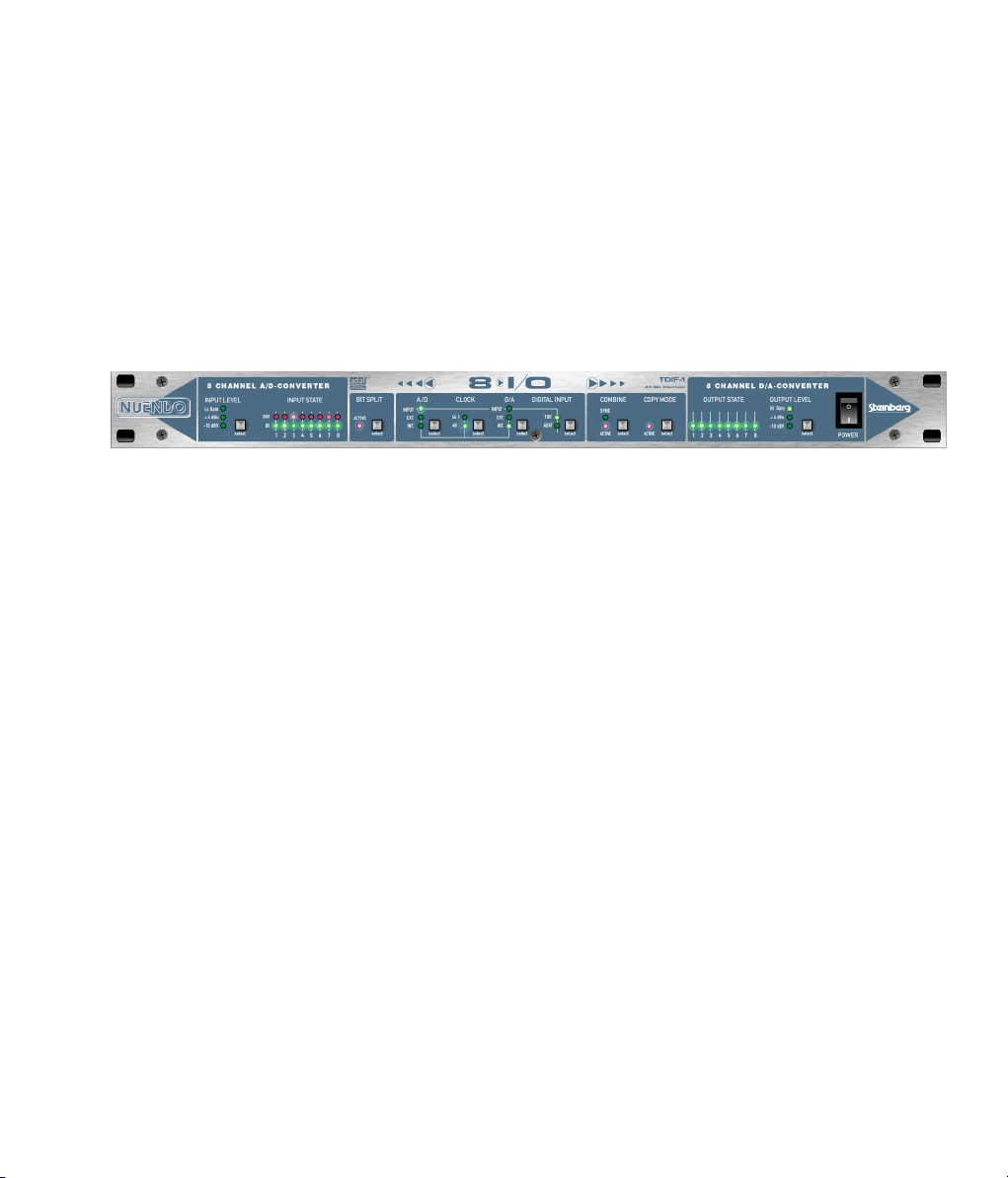
3
Description rapide et caractéristiques
Page 96

NUENDO 8 I/O est un convertisseur AD et DA 8 canaux présenté sous forme d’un rack
de 19” d’une hauteur de 1 U. Les convertisseurs 24 bits les plus récents utilisant un
oversampling 128 fois permettent d’obtenir un rapport dynamique supérieur à 110
dB. Cette valeur n’est pas seulement écrite dans cette brochure, grâce à notre Low Jitter Design, elle est présente dans chaque unité.
L’équilibre des entrées et sorties analogiques s’effectue grâce aux D-sub (pour les câbles XLR optionnels) et les jacks TRS 1/4 de pouce. Le parcours du signal des jacks au
convertisseur analogique numérique (ADC) est équilibré. Les entrées et sorties numériques sont disponibles sous forme de connecteurs ADAT optique et de TDIF-1.
L’un des principaux problèmes avec un convertisseur AD est de maintenir la dynamique au niveau le plus efficace. NUENDO 8 I/O de Steinberg contient des switches élec-
troniques à la pointe de la technologie n’introduisant ni bruit ni distorsion dans le flux
du signal et agissent comme des atténuateurs de niveau. Deux switches sur le panneau frontal contrôlent tous les switches électroniques de tous les canaux pour une
adaptation parfaite aux niveaux les plus fréquents de -10 dBV et +4 dBu. Chaque entrée analogique dispose d’un diode ‘Signal Ok’ et ‘Over’, ainsi les niveaux et les surcharges sont faciles à contrôler.
Le convertisseur AD peut fournir une horloge interne (44,1 et 48 kHz) à toutes les sorties numériques. La technologie exclusive Intelligent Clock Control (ICC) permet une
utilisation flexible de l’horloge interne à 44,1 et 48 kHz, d’une word clock externe ou
des signaux d’entrée numériques. Ces options, aussi disponibles pour la conversion
DA, sont simples. L’état actuel du locking et de la synchronisation de l’horloge est indiqué par des diodes.
La section numérique du NUENDO 8 I/O intègre deux fonctions exceptionnelles. Le Bit
Split permet de séparer un signal 24 bits en deux sorties 16 bits. Cette technique permet par exemple d’utiliser deux lecteurs de cassettes 8 pistes 16 bits pour enregistrer
8 canaux sur 24 bits. L’utilisation du Bit Combine permet de réunir les deux signaux sé-
parés en un seul signal de 24 bits. La méthode de séparation/combinaison est compatible avec le technologie utilisée par la table de mixage numérique Yamaha 02R, aussi
le NUENDO 8 I/O peut-il être utilisé directement avec cette table de mixage en mode
24 bits!
NUENDO 8 I/O
90 Description rapide et caractéristiques
Page 97

De plus, le Copy Mode exclusif permet d’utiliser le périphérique intégralement en numérique. Le Copy Mode envoie le signal de l’entrée numérique aux sorties numériques ADAT et TDIF. Comme ils opèrent simultanément avec des données identiques,
le NUENDO 8 I/O ne devient pas seulement un excellent convertisseur ADAT/TDIF
mais il permet aussi d’effectuer des copies entre appareils de même format et de distribuer le signal entre différents appareils. C’est pourquoi nous appelons le NUENDO 8
I/O une Solution Audio Intelligente.
NUENDO 8 I/O
Description rapide et caractéristiques 91
Page 98

NUENDO 8 I/O
92 Description rapide et caractéristiques
Page 99

4
Données techniques
Page 100

• Alimentation: Interne, 100-240 V AC, 30 Watts
• Dimensions 483 x 44 x 205 mm
• Poids: 2 kg
Spécifications analogique
AD
• Résolution AD: 24 bits
• Rapport signal/bruit : 115 dBA
• THD: < -110 dB, < 0,00032 %
• THD+N: < -102 dB, < 0,0008 %
• Crosstalk: > 130 dB
• Niveau d’entrée maximal AD: +19 dBu
• Réponse en fréquence AD, -0,1 dB: 5 Hz - 21,5 kHz
• Enrtée ligne: 1/4" TRS et D-sub 25 broches, équilibrée
• Impédance de l’entrée ligne: 10 kOhm
• sensibilité de l’entrée commutable: +4 dBu, -10 dBV, Hi Gain
• Niveau d’entrée pour 0 dBFS @ Lo Gain: +19 dBu / -1 dBV
• Niveau d’entrée pour 0 dBFS @ +4 dBu: +13 dBu
• Niveau d’entrée pour 0 dBFS @ -10 dBV: +2 dBV
DA
• Résolution DA: 24 Bit
• Dynamique: 110 dBA (unmuted)
• THD: < -104 dB, < 0,00063 %
• THD+N: < -102 dB, < 0,0008 %
• Crosstalk: > 110 dB
• Niveau de sortie maximal DA: +19 dBu
• Réponse en fréquence DA, -0,1 dB: 5 Hz - 21,6 kHz
• Sortie ligne: 1/4" TRS et D-sub 25 broches, équilibrée
• Impédance de la sortie ligne: 47 Ohm
• Niveau de sortie commutable: Hi Gain, +4 dBu, -10 dBV
• Niveau de sortie à 0 dBFS @ Hi Gain: +19 dBu
• Niveau de sortie à 0 dBFS @ +4 dBu: +13 dBu
• Niveau de sortie à 0 dBFS @ -10 dBV: +2 dBV
NUENDO 8 I/O
94 Données techniques
 Loading...