

Page 1
Page 2

Table of Contents
1. Introduction........................................................................................................6
2. Package Contents.............................................................................................7
3. System Requirements......................................................................................7
4. Brief Description and Characteristics.........................................................8
5. Technical Specifications.................................................................................8
6. Hardware Installation...................................................................................12
7. Software Installation.....................................................................................13
8. Operation and Usage....................................................................................16
9. Configuring the Digiset or Multiset.........................................................24
10. Word Clock.....................................................................................................37
11. Using more than one Nuendo Audiolink 96......................................39
12. Special Characteristics of the S/P-DIF Output...................................39
13. Operation under ASIO 2.0.........................................................................41
14. TotalMix: Routing and Monitoring........................................................45
15. Notes on using Laptops and CardBus..................................................52
16. Problems and Solutions............................................................................55
17. Software and Hardware Compatibility................................................58
18. Installation problems (Windows)...........................................................58
19. Warranty..........................................................................................................59
20. Trademarks....................................................................................................59
21. Diagrams.........................................................................................................61
NUENDO AUDIOLINK 96
ii
Page 3

ENGLISH
Inhaltsverzeichnis
1. Einleitung..........................................................................................................70
2. Lieferumfang....................................................................................................71
3. Systemvoraussetzungen..............................................................................71
4. Kurzbeschreibung und Eigenschaften....................................................72
5. Technische Merkmale...................................................................................72
6. Installation der Hardware............................................................................76
7. Installation der Treiber..................................................................................77
8. Inbetriebnahme und Bedienung..............................................................80
9. Konfiguration des Digiset bzw. Multiset................................................89
10. Wordclock....................................................................................................103
11. Betrieb mehrerer Nuendo Audiolink 96-Karten.............................105
12. Besonderheiten des S/P-DIF Ausganges..........................................105
13. Betrieb unter ASIO 2.0.............................................................................107
14. TotalMix: Routing und Monitoring.....................................................111
15. Hinweise zu Notebooks und CardBus...............................................119
16. Probleme und Lösungen........................................................................122
17. Soft- und Hardware-Kompatibilität....................................................125
18. Installationsprobleme (Windows).......................................................125
19. Garantie........................................................................................................126
20. Warenzeichen.............................................................................................126
21. Diagramme..................................................................................................128
NUENDO AUDIOLINK 96
iii
Page 4

NUENDO AUDIOLINK 96
iv
Page 5

ENGLISH
Nuendo Audiolink 96
Audiolink 96 PCI (PCI Interface Card)
Audiolink 96 Mobile (CardBus Interface Card)
Nuendo Audiolink Digiset (In/Out-Box)
Nuendo Audiolink Multiset (In/Out-Box)
Operation Manual
NUENDO AUDIOLINK 96
English – 5
Page 6

❐
1. Introduction
This manual describes how to use the Nuendo Audiolink 96 on computers
running different operating systems. If a text section only refers to one of
the compatible operating systems, this will be indicated.
Thank you for choosing the Nuendo Audiolink 96. This unique audio
system is capable of transferring digital audio data directly to a computer from practically any device equipped with a digital audio interface, be it S/P-DIF, AES/EBU or ADAT optical.
The numerous unique features and well thought-out configuration dialog puts the Nuendo Audiolink 96 at the very top of the range of digital
audio interface cards.
The package includes drivers for Windows and MacOS.
Installation under Windows is simple, even for the inexperienced user,
thanks to the latest Plug and Play technology and full interrupt-sharing.
Our high-performance philosophy guarantees maximum system per-
formance by executing all functions directly in hardware and not in the
driver (i.e. the CPU).
NUENDO AUDIOLINK 96
English – 6
Page 7

2. Package Contents
Please check that your Nuendo Audiolink 96 system package contains
the following:
ENGLISH
Nuendo Audiolink 96
• Audiolink 96 PCI card
• Driver CD
• Cable IEEE1394, 4.5 m
• Internal cable (3 pin)
Audiolink 96 Mobile CardBus Interface Card
• PCMCIA type II CardBus card
• Driver CD
• Cable CardBus to IEEE1394, 4.5 m
• 12 V car cable
• Battery cable
• Power supply 12 V/1.25 A and power cord
Digiset or Multiset-In/Out Box
• Digiset or Multiset I/O box
• 3 optical cable (TOSLINK), 2 m
PCI Interface Card
3. System Requirements
• Windows 98, Windows 2000, Windows XP or MacOS (version 9.1 or later, G3 300 MHz recommended)
• PCI Interface: a free PCI rev. 2.1 Busmaster slot
• CardBus Interface: a free PCMCIA Slot type II, CardBus-compatible
NUENDO AUDIOLINK 96
English – 7
Page 8

4. Brief Description and Characteristics
• 0% (zero!) CPU load, even when using all 36 (Multiset) or 52 (Digiset)
ASIO channels
• All settings can be changed in real-time
• Enhanced mixed mode: Analog, ADAT In, S/PDIF In, and all outputs can be used
simultaneously (Multiset). ADAT In, S/P-DIF In and all outputs can be used simultaneously (Digiset).
• 8 available buffer sizes/latencies: 1.5 / 3 / 6 / 12 / 23 / 46 / 93 / 186 ms
• Sample Split technology for 4 channels (Multiset) or 12 channels (Digiset)
96 kHz/24-bit record/playback via ADAT optical
• Slave and master clock modes
• Automatic and intelligent master/slave clock control
• Unsurpassed Bitclock PLL (audio synchronization) in ADAT mode
• Word clock input and output
• ADAT Sync in (9-pin D-type) for sample-accurate transfer
• Zero Latency Monitoring: Hardware bypass per track, controlled by Punch in/
out
• Enhanced ZLM for latency-free submixes and perfect ASIO Direct Monitoring
• SyncAlign guarantees sample aligned, non-swapping channels
• SyncCheck tests and reports the synchronization status of input signals
• 1 x MIDI I/O, 16 channels high-speed MIDI (Multiset) or 2 x MIDI I/O, 32 channels
high-speed MIDI (Digiset)
• 1 x Analog Line/headphone output, separate mixer for independent submix
• TotalMix: mixer with 40 bit internal resolution and 720 channels (Multiset) or
1456 channels (Digiset)
5. Technical Specifications
5.1 Digital – Multiset & Digiset
Multiset
• Super Low Jitter Design: < 3 ns word clock PLL, < 2 ns ADAT PLL, < 1 ns internal
• Internal sample rates: 32 / 44.1 / 48 / 88.2 / 96 kHz
• Supported sample rats through word clock: 27 kHz - 103 kHz
• Internal resolution: 24 Bit
• Input PLL ensures zero dropout, even at more than 40 ns jitter
• Bitclock PLL for trouble-free varispeed operation in ADAT mode
NUENDO AUDIOLINK 96
English – 8
Page 9

AD
• High-sensitivity input stage (< 0.2 Vss input level)
• Output voltage 0.8V (consumer mode, phono) or 2.3V (professional mode)
• Phono input and output ground-free transformer coupled
• Connectors: optical (TOSLINK), phono, BNC
• Clocks: ADAT Sync In, word clock I/O
• Formats: S/P-DIF (Consumer and Professional), ADAT optical
Digiset
• Super Low jitter S/P-DIF: < 3 ns in PLL mode (44.1 kHz, optical in)
• Super Low jitter ADAT: < 2 ns in PLL mode (44.1 kHz, optical in)
• Input PLL ensures zero dropout, even at more than 40 ns jitter
• Bitclock PLL for trouble-free varispeed operation in ADAT mode
• High-sensitivity input stage (< 0.2 Vss input level)
• Output voltage 0.8V (consumer mode, phono) or 2.3V (professional mode)
• Sample frequencies: 32 / 44.1 / 48 / 88.2 / 96 kHz and variable
• Phono input and output ground-free transformer coupled
• Connectors: optical (TOSLINK), phono, BNC
• Clocks: ADAT Sync In, word clock I/O
• Formats: S/P-DIF (Consumer and Professional), ADAT optical
ENGLISH
5.2 Analog Output – Multiset
Stereo Monitor Output
• Analog output level +8 dBu @ 0 dBFS
• Dynamic range output: 108 dB (RMS unweighted, unmuted), 112 dBA
• THD+N output: -100 dB / 0.001%
• Frequency response DA, -0.1 dB: 20 Hz - 20.8 kHz (sf 44,1 kHz)
• Frequency response DA, -0.5 dB: 10 Hz - 44 kHz (sf 96 kHz)
• Samplerates playback: 32/44.1/48/64/88.2/96 kHz and variable (word clock)
• Ouput impedance: 75 Ohm
• Channel separation: > 110 dB
• Resolution AD: 24 Bit
• Signal to Noise ratio: 101 dB RMS unweighted, 106 dBA
• THD: < -107 dB, < 0.00045 %
• THD+N: < -96 dB, < 0.0016 %
• Crosstalk: > 120 dB
NUENDO AUDIOLINK 96
English – 9
Page 10

DA
• Analog headroom prior to AD conversion: 13 dB
• Frequency response AD @ 44.1 kHz, -0.5 dB: 5 Hz - 20.7 kHz
• Frequency response AD @ 96 kHz, -0.5 dB: 5 Hz - 32 kHz
• Input Line: 1/4" TRS jack, servo balanced
• Input impedance Line: > 5 kOhm
• Input sensitivity through jumper: Lo Gain, +4 dBu, -10 dBV
• Input level for 0 dBFS @ Lo Gain: +19 dBu
• Input level for 0 dBFS @ +4 dBu: +13 dBu
• Input level for 0 dBFS @ -10 dBV: +2 dBV
• Resolution DA: 24 Bit
• Signal to Noise ratio: 108 dB RMS unweighted, 111 dBA (unmuted)
• THD: < - 98 dB, < 0.0013 %
• THD+N: < -91 dB, < 0.002 %
• Crosstalk: > 100 dB
• Maximum output level DA: +19 dBu
• Frequency response DA @ 44.1 kHz, -0.5 dB: 5 Hz – 20.9 kHz
• Frequency response DA @ 96 kHz, -0.5 dB: 5 Hz - 35 kHz
• Output Line: 1/4" TRS jack, servo balanced
• Output impedance Line: 47 Ohm
• Output level through jumper: Hi Gain, +4 dBu, -10 dBV
• Output level at 0 dBFS @ Hi Gain: +19 dBu
• Output level at 0 dBFS @ +4 dBu: +13 dBu
• Output level at 0 dBFS @ -10 dBV: +2 dBV
5.3 Analog Output – Digiset
• Analog output level +10 dBu @ 0 dBFS
• Dynamic range output: 108 dB (RMS unweighted, unmuted), 112 dBA
• THD+N output: -100 dB / 0.001%
• Frequency response DA, -0.1 dB: 20 Hz - 20.8 kHz (sf 44,1 kHz)
• Frequency response DA, -0.5 dB: 10 Hz - 44 kHz (sf 96 kHz)
• Sample rates playback: 32 / 44.1 / 48 / 64 / 88.2 / 96 kHz and variable (word
clock)
• Ouput impedance: 75 Ohm
• Channel separation: > 110 dB
NUENDO AUDIOLINK 96
English – 10
Page 11

5.4 Transfer Modes: Resolution/Bits per Sample
Windows
ASIO:
24 or 32 bit, 4 bytes stereo 8 bytes
This format is compatible with 16-bit and 20-bit. Resolutions below 24bit are handled by the audio application.
MME:
16 bit, 2 bytes stereo 4 bytes
20 bit, 3 bytes MSB stereo 6 bytes
20 bit, 4 bytes MSB stereo 8 bytes
24 bit, 3 bytes stereo 6 bytes
24 bit, 4 bytes MSB stereo 8 bytes
32 bit, 4 bytes stereo 8 bytes
ENGLISH
Channel Interleave operation is not supported. As no additional Channel Status bits are transferred TMS (Track Marker Support) is not available.
Macintosh
32 bit, 4 bytes stereo 8 bytes
This format is compatible with 16-bit and 20-bit. Resolutions below 24bit are handled by the audio application. The card works internally with
32-bit data, but audio data transfer is limited to 24-bits.
NUENDO AUDIOLINK 96
English – 11
Page 12

❐
6. Hardware Installation
6.1 Audiolink 96 PCI Interface
Before installing the PCI card, please make sure the computer is switched
off and the power cable is disconnected from the mains supply. Inserting
or removing a PCI card while the computer is in operation can cause irreparable damage to both motherboard and card!
1. Disconnect the power cord and all other cables from the computer.
2. Remove the computer's housing. Further information on how to do this
can be found in your computer´s instruction manual.
3. Important: Before removing the card from its protective bag, discharge
any static in your body by touching the metal chassis of the PC.
4. Insert the PCI card firmly into a free PCI slot, press and fasten the screw.
5. Replace the computer's housing.
6. Reconnect all cables including the power cord.
7. Connect PCI interface and Digiset using the supplied cable (IEEE1394).
This is a standard Firewire cable (6-pin).
6.2 Audiolink 96 Mobile Card
Before inserting the CardBus card make sure the complete Audiolink 96
system is ready for operation!
1. Connect the CardBus card with the Digiset using the supplied cable.
2. Insert the CardBus card with the Nuendo logo up into a PCMCIA slot.
3. Plug the power jack of the supplied switching power supply into the connector labeled AUX, on the rear of the Digiset.
4. Connect power cord to power supply, plug into AC outlet. The green LED
of the power supply and the red LED of the Digiset will light up.
NUENDO AUDIOLINK 96
English – 12
Page 13

❐
❐
5. Switch on the notebook and boot the operating system.
The small 15-pin connector of the CardBus card is coded. Only the supplied special cable can be plugged in, and only when the metal sleeve is
up. Forcefully plugging in or out can cause damage to the CardBus card.
7. Software Installation
7.1 Windows 98
After the interface has been installed and connected to the Digiset or
Multiset (see page 12), and the computer has been switched on, Windows will recognize the new hardware component and start its ‘Add
New Hardware Wizard’. Insert the Driver CD into your CD-ROM drive
and follow the instructions on your computer screen.
Windows will install the Nuendo Audiolink 96 System driver and register the card in the system as a new audio device. The Nuendo Audiolink
96 system is now ready for use.
ENGLISH
Unfortunately, there are rare cases where the CD-ROM path (i.e. its driveletter) has to be typed in again during the copy process.
The Audiolink 96 system can be easily configured via its Settings dialog
(see page 27).
7.2 Windows 2000
After the interface has been installed and connected to the Digiset or
Multiset (see page 12), and the computer has been switched on, Windows will recognize the new hardware component and start its ‘Hardware Wizard’. Insert the Driver CD into your CD-ROM drive and follow
the instructions on your computer screen. The driver files are located in
the directory
Windows will install the Nuendo Audiolink 96 System driver and register the card in the system as a new audio device. After a reboot the Nuendo Audiolink 96 system is ready for use.
\win2000
on the Driver CD.
NUENDO AUDIOLINK 96
English – 13
Page 14

❐
❐
Unfortunately, there are rare cases where the CD-ROM path (i.e. its driveletter) has to be typed in again during the copy process.
The Audiolink 96 system can be easily configured via its Settings dialog
(see page 27).
In case the warning messages 'Digital signature not found' or 'Do not
install driver' appear, don't worry, just continue with the installation.
7.3 Macintosh
First fit the card (see page 12), then switch on the computer and install
the drivers from the Driver CD. The driver files are located in the folder
'Nuendo Audiolink 96'.
In case a newer driver version was downloaded from the website, doubleclick the 'madsp_x.sit' archive to decompress it into separate files
(using 'Aladin Stuffit Expander').
If you already installed an older version of the driver first make sure to remove it. To do so open the 'Extensions' folder which is inside your 'System'
folder. Remove the file 'Nuendo Audiolink 96 Driver'. Also remove 'Nuendo
Audiolink 96 Settings' from the directory where it was copied to. Remove
the 'Nuendo Audiolink 96 ASIO' driver file from any 'ASIO Drivers' folder.
Drag the new file Nuendo Audiolink 96 Driver to the System folder. It
will be installed automatically into the 'Extension' folder. Confirm the
system's message to complete the installation. The driver file must now
be located in the 'Extension' folder.
Copy the new files Nuendo Audiolink 96 Settings and Nuendo
Audiolink 96 ASIO into all 'ASIO Drivers' folders found on your com-
puter. As every ASIO software has its own ASIO Drivers folder the files
have to be copied several times.
Configuration of the Nuendo Audiolink 96 is done through the Settings
dialog, which can be called from within any ASIO compatible software
(for example Audio/System/ASIO Control Panel). To be able to call up
the Settings dialog at any time we recommend to create an alias on the
NUENDO AUDIOLINK 96
English – 14
Page 15

❐
❐
desktop. To create an alias select 'Nuendo Audiolink 96 Settings' with
the mouse cursor, press and hold the [Apple] and [Alt] keys on your
keyboard, and drag 'Nuendo Audiolink 96 Settings' to the desired location. See also page 24.
The driver archive includes not only the three driver files Nuendo
Audiolink 96 Driver, Nuendo Audiolink 96 Settings and Nuendo
Audiolink 96 ASIO, but also the following files:
digibox.bin Firmware of the Digiset I/O box
default.mix Default settings for TotalMix
default.vol Default settings for Digiset, as long as TotalMix
isn't started
preset1.mix to
preset8.mix
Presets for the Audiolink 96 mixer
These files must all be copied to the System folder 'Preferences'!
The file 'digibox.bin' includes the firmware of the Digiset, which is
loaded automatically into the Digiset during boot of the computer.
ENGLISH
The files 'default.mix' and 'default.vol' include the latest mixer state.
The files 'preset1.mix' to 'preset8.mix' include the complete mixer state,
which can be called via the Preset buttons in the Quick Access Panel of
TotalMix.
The file ' Nuendo Audiolink 96 TotalMix ' can be copied to any location. When started the Audiolink 96 mixer comes up and allows you to
configure the digital real-time mixer of the Digiset.
TotalMix requires Carbon Library 1.1, which is part of the operating
system since MacOS 9.1. After installation of Carbon Library 1.1 TotalMix
can even be run on older systems (down to 8.6).
To finish installation reboot the computer.
NUENDO AUDIOLINK 96
English – 15
Page 16

8. Operation and Usage
8.1 Connections
Digiset
The front of the I/O-box Digiset has the second MIDI input and output,
the analog stereo output of the digital mixer, and several status LEDs:
MIDI State indicates sent or received data separately for each MIDI
port.
Input State indicates a valid input signal separately for each input.
SyncCheck shows through a blinking LED which of the input signals is
locked but not in sync with the others. See page 31.
The red HOST LED lights up when the power supply or the computer is
switched on, this signalling the presence of operating voltage. At the
same time it operates as Error LED, in case the I/O-box wasn’t initialised,
or the connection to the interface has been interrupted (cable not connected etc.).
Phones is a low impedance line output of highest quality which can
produce sufficient volume undistorted even in connected headphones.
The back of the Digiset has the first MIDI input and output, the power
supply connector AUX (only needed with CardBus operation), and all
digital inputs and outputs:
ADAT I/O (TOSLINK), 1 to 3. The ADAT1 I/O can also be used for optical
S/P-DIF, if this mode is selected in the Settings dialog.
S/P-DIF I/O coaxial (phono).
Wordclock I/O (BNC).
ADAT Sync In (D-sub 9-pin).
The S/P-DIF inputs are selected via the Settings dialog (started by clicking on the Nuendo symbol in the system tray). The Audiolink 96 system
accepts the commonly used digital audio formats, S/P-DIF as well as
AES/EBU. Channel status and copy protection are ignored.
NUENDO AUDIOLINK 96
English – 16
Page 17
In S/P-DIF mode, identical signals are available at both the optical and
the coaxial outputs. An obvious use for this would be simply connecting two devices, i.e. using the Audiolink 96 as a splitter (distribution 1
on 2).
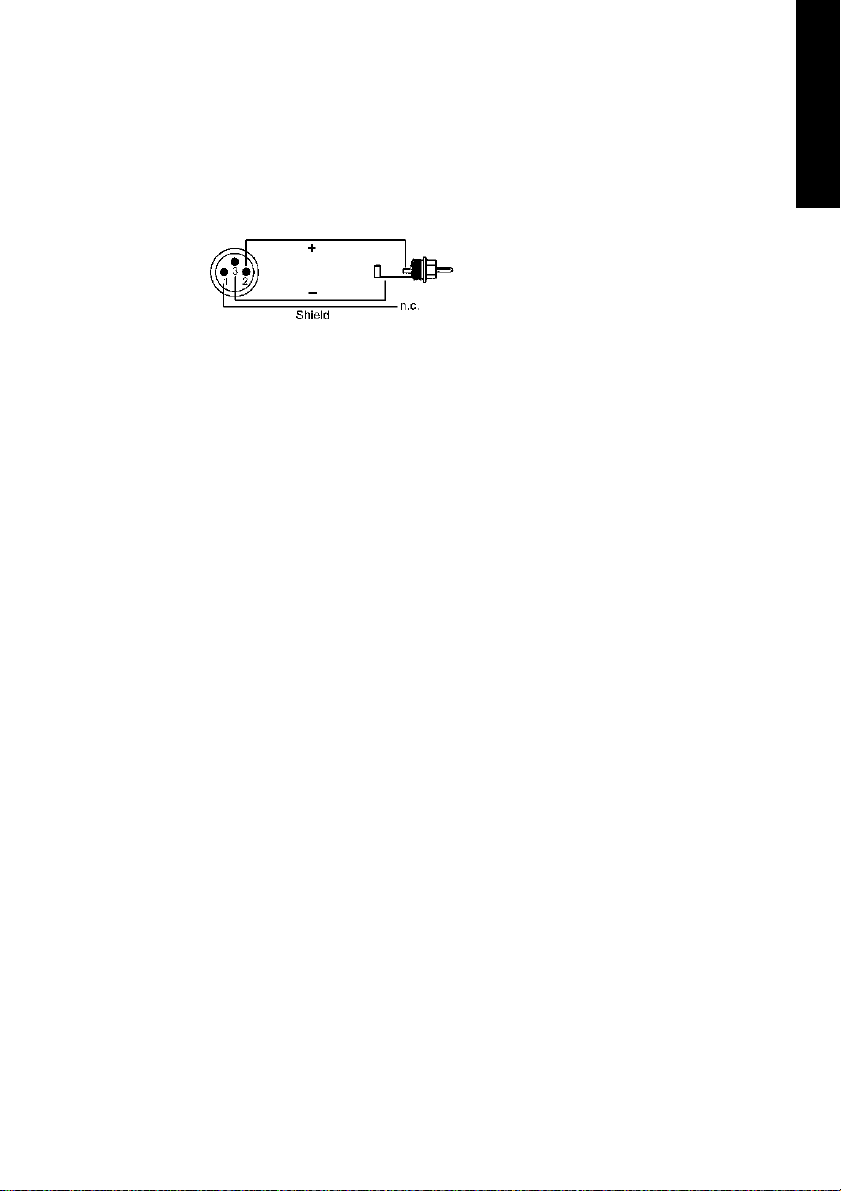
To receive signals in AES/EBU format,
an adapter cable is required. Pins 2
and 3 of an XLR plug are connected
individually to the two pins of a
phono plug. The cable shielding is
only connected to pin 1 of the XLR - not to the phono plug.
The ground-free design using transformers for digital inputs and out-
puts enables trouble-free connection even to AES/EBU devices, and
perfect hum rejection.
Multiset
The front of the I/O-box Multiset has the second MIDI input and output,
the analog stereo output of the digital mixer, and several status LEDs:
ENGLISH
MIDI State indicates sent or received data separately for each MIDI
port.
Input State indicates a valid input signal separately for each input.
SyncCheck shows through a blinking LED which of the input signals is
locked but not in sync with the others. See “9.2 Clock Modes - Synchronization” on page 31.
The red HOST LED lights up when the power supply or the computer is
switched on, thus signalling the presence of operating voltage. At the
same time it operates as Error LED, in case the I/O-box wasn’t initialised,
or the connection to the interface has been interrupted (Error, cable
not connected etc.).
Phones is a low impedance line output of highest quality which can
produce sufficient volume undistorted even in connected headphones.
The back of the Multiset has the first MIDI input and output, the power
supply connector AUX (only needed with CardBus operation), and all
digital inputs and outputs:
NUENDO AUDIOLINK 96
English – 17
Page 18
ADAT I/O (TOSLINK), 1 to 3. The ADAT1 I/O can also be used for optical
S/P-DIF, if this mode is selected in the Settings dialog.
S/P-DIF I/O coaxial (phono).
Word clock I/O (BNC).
ADAT Sync In (D-sub 9-pin).
The S/P-DIF inputs are selected via the Settings dialog (started by clicking on the Nuendo symbol in the system tray). The Audiolink 96 system
accepts the commonly used digital audio formats, S/P-DIF as well as
AES/EBU. Channel status and copy protection are ignored.
In S/P-DIF mode, identical signals are available at both the optical and
the coaxial outputs. An obvious use for this would be simply connecting two devices, i.e. using the Audiolink 96 as a splitter (distribution 1
on 2).
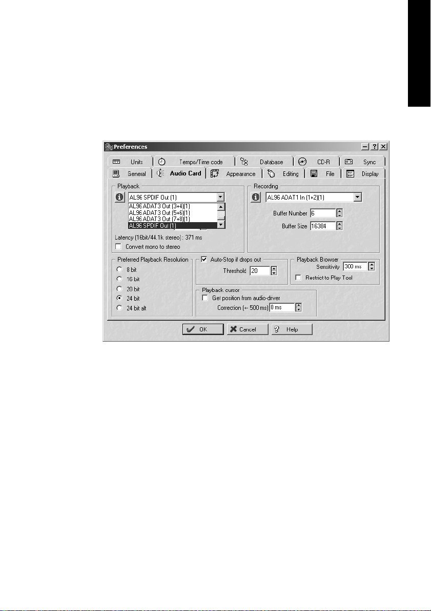
To receive signals in AES/EBU format,
an adapter cable is required. Pins 2
and 3 of an XLR plug are connected
individually to the two pins of a
phono plug. The cable shielding is
only connected to pin 1 of the XLR - not to the phono plug.
The ground-free design using transformers for digital inputs and out-
puts enables trouble-free connection even to AES/EBU devices, and
perfect hum rejection.
8.2 Windows MME Playback
The Audiolink 96 system automatically outputs digital audio data using
the wave file's parameters in case they are supported. Otherwise an error message appears.
In the audio application being used, Audiolink 96 must be selected as
output device. This can often be found in the Options, Preferences or
Settings menus under Playback Device, Audio Devices, Audio etc. We
recommend using 24-bit resolution for playback, to make full use of the
Audiolink 96’s potential.
NUENDO AUDIOLINK 96
English – 18
Page 19
We strongly recommend switching all system sounds off (via >Control
Panel/Sounds<). Also Audiolink 96 should not be the Preferred Device
for playback, as this could cause loss of synchronization and unwanted
noises. If you feel you cannot do without system sounds, you should
consider buying a cheap Blaster clone and select this as Preferred Device in >Control Panel/Multimedia/Audio<.
ENGLISH
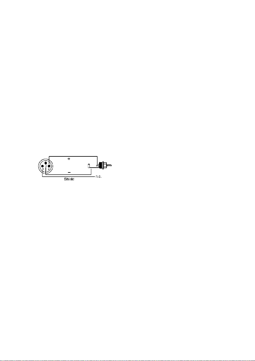
The screenshot above shows a typical configuration dialog as displayed by a (stereo) wave editor. After selecting a device, audio data is
sent either to S/P-DIF or to the ADAT ports, depending on which has
been selected as playback device.
Increasing the number and/or size of audio buffers may prevent the audio signal from breaking up, but also increases latency, i.e. output is delayed. For synchronized playback of audio and MIDI (or similar), be sure
to activate the checkbox ‘Get position from audio driver’. Even at
higher buffer settings in a mixed Audio/MIDI environment, sync problems will not arise because the Nuendo Audiolink 96 always reports the
current play position correctly (even while recording - essential for
chase lock synchronization).
NUENDO AUDIOLINK 96
English – 19
Page 20

The Audiolink 96 system’s ADAT optical interface allows sample rates
of up to 96 kHz using a standard ADAT recorder. Single-channel data at
this frequency requires two ADAT channels, achieved using the ‘Sample Split’ technique. This reduces the number of available ADAT channels from 24 to 12. Under Windows MME, channels are routed to ADAT
devices in double-speed mode as follows:
• Only stereo pairs (1+2) and (3+4) of each ADAT port are available
• Channel 1 is routed to channels 1 and 2, channel 2 is routed to 3 and 4 etc.
Please refer to the diagram ‘ADAT Track Routing, MME 96 kHz’. Routing
for record and playback is identical.
8.3 Windows MME Recording
Unlike analog soundcards which produce empty wave files (or noise)
when no input signal is present, digital I/O cards always need a valid input signal to start recording.
To take this into account, three unique features are included in the Nuendo Audiolink 96 system: a comprehensive I/O signal status display
(showing sample frequency, lock and sync status) in the Settings dialog, status LEDs for each input, and the Check Input safety function.
If a 48 kHz signal is fed to the input and the application is set to 44.1
kHz, Check Input stops the system from recording. This prevents faulty
takes, which often go unnoticed until later on in the production. Such
tracks appear to have the wrong playback rate - the audio quality as
such is not affected.
The sample frequency shown in the Settings dialog (see section “9.
Configuring the Digiset or Multiset” on page 24) is useful as a quick display of the current configuration (the board itself and all connected external equipment). If no sample frequency is recognized, it will read ‘No
Lock’.
With this configuration any suitable audio application for digital recording is simple. After selecting the required input, Nuendo Audiolink
96 displays the current sample frequency. This parameter can then be
changed in the application’s audio attributes (or similar) dialog.
NUENDO AUDIOLINK 96
English – 20
Page 21
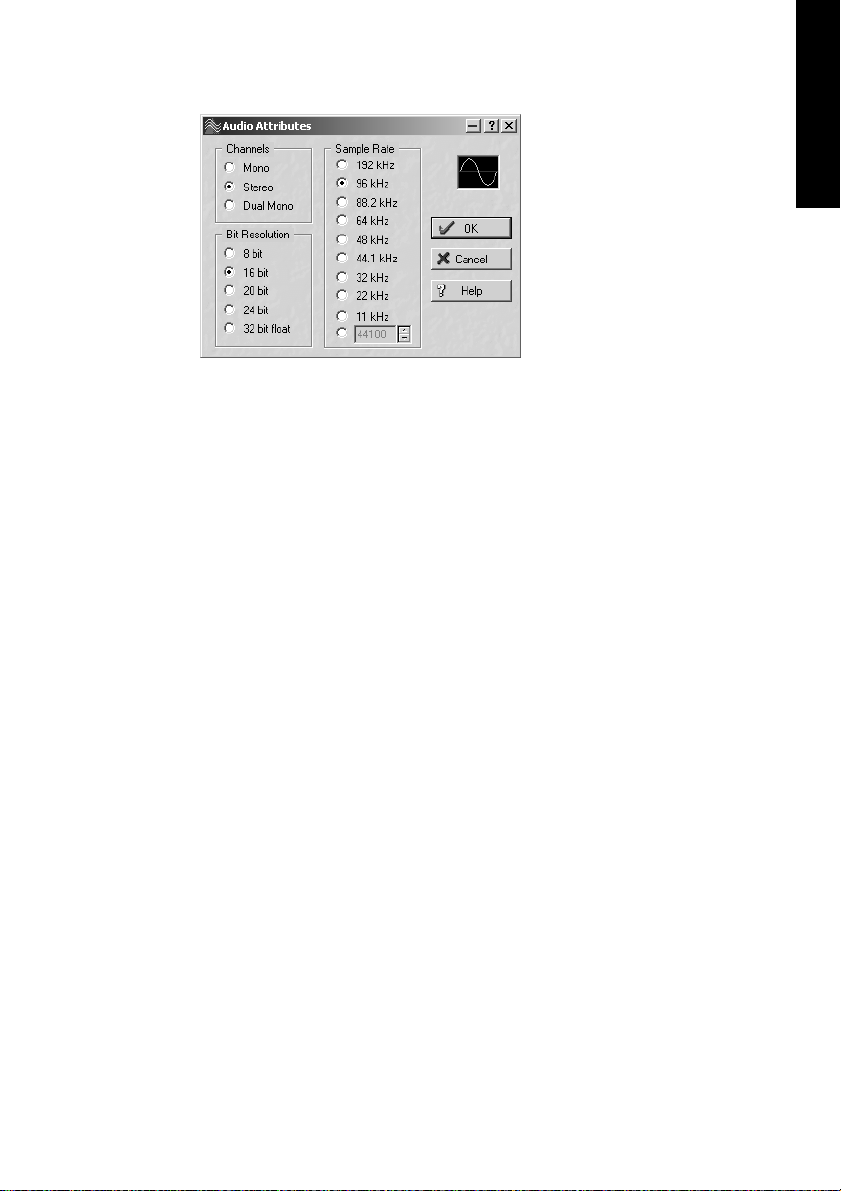
The screenshot to the left
shows a typical dialog used
for changing basic parameters
such as sample frequency and
resolution in an audio application.
Any bit resolution can be selected, providing it is supported by both the audio
hardware and the software.
Even if the input signal is 24
bit, the application can still be set to record at 16-bit resolution. The
lower 8 bits (and therefore any signals about 96dB below maximum
level) are lost entirely. On the other hand, there is nothing to gain from
recording a 16-bit signal at 24-bit resolution - this would only waste
precious space on the hard disk.
It often makes sense to monitor the input signal or send it directly to
the output. This can either be done at zero latency using TotalMix (see
the section “14. TotalMix: Routing and Monitoring” on page 45) or via
the Nuendo Audiolink 96 system’s useful real-time input monitor function (see Monitoring in the Settings dialog). Activating Record or Pause
in the application causes the input signal to be routed directly to the
corresponding output.
ENGLISH
Currently two solutions exist which enable an automated control of
real-time monitoring. ZLM (Zero Latency Monitoring) allows monitoring in Punch I/O mode - with this the system behaves like a tape machine. This method has been implemented in all versions of
Samplitude (by SEK’D), and can be activated using the global track option 'Hardware monitoring during Punch'.
The other solution is Steinberg’s ASIO protocol with our ASIO 2.0 drivers and all ASIO 2.0 compatible programs. When 'ASIO Direct Monitoring' has been switched on the input signal is routed in real-time to the
output whenever Record is started. As opposed to ZLM the monitored
signal can be freely mixed and routed, and is not restricted to the same
channel.
NUENDO AUDIOLINK 96
English – 21
Page 22

8.4 Recording analog – Multiset
For recordings via the analog inputs the corresponding record device
has to be chosen (Audiolink 96 Analog (x+x)). Apart from the internal
jumpers which set the basic operating level, the Multiset has no means
to change the input level. This would make no sense for the digital inputs, but also for the analog inputs one can do without it. It doesn't
matter if the Multiset is operated at a mixing desk or a multichannel
Mic preamp, in either case the level can be controlled directly at the
source to match the Multiset's sensitivity perfectly.
The input sensitivity of the analog inputs can be changed through internal jumpers to meet the most often used studio levels, see page 35.
8.5 Analog Inputs – Multiset
The Multiset provides 8 balanced Line inputs via 1/4" TRS (stereo) jacks.
The electronic input stage is built in a servo balanced design which
handles monaural and stereo jacks correctly. When used unbalanced it
automatically corrects the gain by 6 dB.
❐
When using unbalanced cables with stereo TRS jacks, the 'ring' contact of
the cable's jack should be connected to pin 1 (ground). Otherwise noise may
occur, caused by the unconnected negative input of the balanced input.
One of the main issues when working with an AD-converter is to maintain the full dynamic range within the best operating level. Therefore the
Multiset includes internal jumpers which allow a perfect adaptation for
all 8 channels seperately to the three most often used studio levels.
The 'standardized' studio levels do not result in a (often desired) full scale
level, but take some additional digital headroom into consideration. The
amount of headroom is different in different standards and again differently implemented by different manufacturers. Because of this we decided to define the levels of the Multiset in a most compatible way.
Reference 0 dBFS @ Headroom
Lo Gain +19 dBu 15 dB
+4 dBu +13 dBu 9 dB
-10 dBV +2 dBV 12 dB
NUENDO AUDIOLINK 96
English – 22
Page 23

The device ships with +4 dBu as factory default. The according headroom meets the latest EBU recommendations for Broadcast usage.
At -10 dBV 12 to 15 dB headroom are common practice, each mixing
desk operating at -10 dBV is able to send and receive much higher levels. Lo Gain allows to work with high levels, best suited for professional
users who prefer to work balanced and at highest levels.
Information on how to change the jumpers can be found in the section
“9.3 Changing the Jumper Settings – Multiset” on page 35.
8.6 Analog Outputs – Multiset
The 8 short circuit protected, low impedance and servo balanced line
outputs are available as (stereo) 1/4" TRS jacks. The electronic output
stage is built in a servo balanced design which handles monaural and
stereo jacks correctly. When used unbalanced it automatically corrects
the gain by 6 dB.
To maintain an optimum level for devices connected to the analog outputs the Multiset includes internal jumpers which allow to change the
level of all 8 outputs separately.
As with the analog inputs the analog output levels are defined to maintain a problem-free operation with most other devices. The headroom
of the Multiset lies between 9 and 15 dB, according to the chosen reference level:
ENGLISH
Reference 0 dBFS @ Headroom
Hi Gain +19 dBu 15 dB
+4 dBu +13 dBu 9 dB
-10 dBV +2 dBV 12 dB
The device ships with +4 dBu as factory default. The according headroom meets the latest EBU recommendations for Broadcast usage.
At -10 dBV 12 to 15 dB headroom are common practice, each mixing
desk operating at -10 dBV is able to send and receive much higher levels. Hi Gain allows to work with high levels, best suited for professional
users who prefer to work balanced and at highest levels.
Information on how to change the jumpers can be found on page 35.
NUENDO AUDIOLINK 96
English – 23
Page 24

9. Configuring the Digiset or Multiset
9.1 General Information
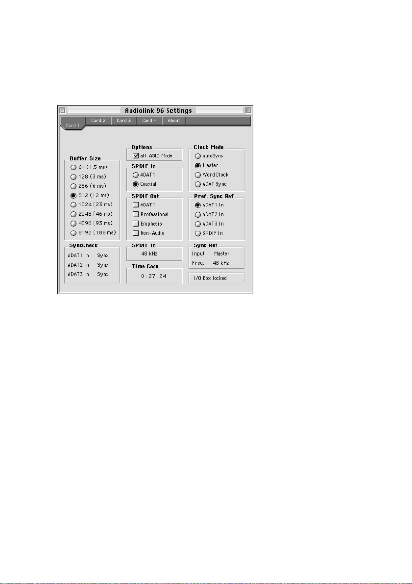
Macintosh
Configuring the Audiolink 96 system is done using its own settings dialog, the program Audiolink 96 Settings.
The Audiolink 96’s hardware offers a number of helpful, well thoughtthrough practical functions and options which affect how the card operates. It can be configured to suit many different requirements. The
following is available in the 'Settings' dialog:
• Input selection
• Output mode
• Output channel status
• Synchronization behaviour
• Input and output status display
• Time code display
NUENDO AUDIOLINK 96
English – 24
Page 25

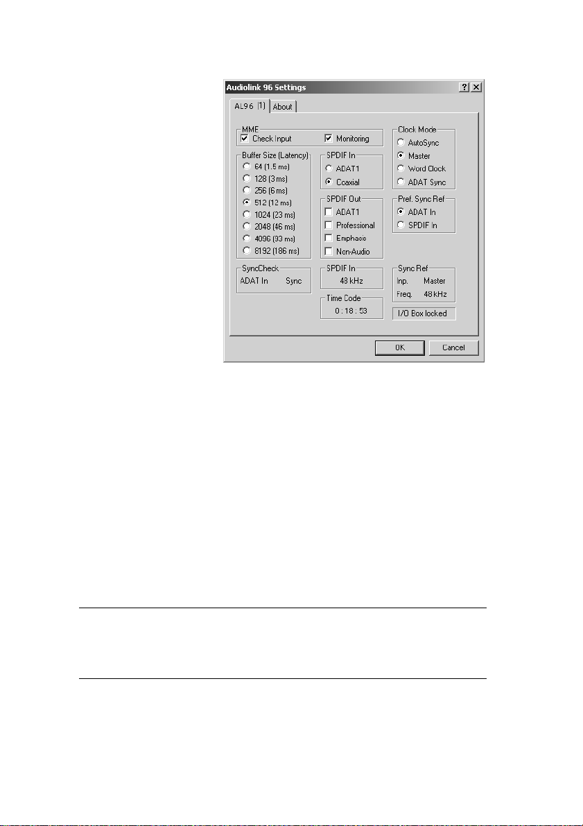
Any changes made in the Settings dialog are applied immediately
– confirmation (e.g. by clicking on OK or exiting the dialog) is not required. However, settings should not be changed during playback or
recording if it can be avoided, as this can cause unwanted noises. Also,
please note that even in 'Stop' mode, several programs keep the recording and playback devices open, which means that any new settings might not be applied immediately.
The status displays at the bottom of the dialog box give the user precise information about the current status of the system, and the status
of all signals. ‘SyncCheck’ indicates whether there is a valid signal for
each input (‘Lock’ or ‘No Lock’), or if there is a valid and synchronous
signal (‘Sync’). The ‘Sync Ref’ display shows the input and frequency of
the current sync source.
'Time Code' displays time information received from the card’s ADAT
Sync In. This is convenient for checking whether the system is running
in time with the transmitting device (e.g. ADAT).
Buffer Size
The setting ‘Buffer Size’ determines the latency between incoming and
outgoing data, as well as affecting system stability (see section “9.3
Changing the Jumper Settings – Multiset” on page 35). We recommend
selecting the highest value here (8192 samples) - the board itself will
still run comfortably. Under Windows MME, buffer sizes (and therefore
latency) can only be set within the audio application being used. Under
GSIF the latency is fixed.
ENGLISH
NUENDO AUDIOLINK 96
English – 25
Page 26
S/P-DIF In
Defines the input for the S/P-DIF signal. 'Coaxial' relates to the phono
socket, 'ADAT1' to the optical input ADAT1.
S/P-DIF Out
The S/P-DIF output signal is constantly available at the phono plug. After selecting 'ADAT1' it is also routed to the optical output ADAT1. For
further details about the settings ‘Professional’, ‘Emphasis’ and ‘NonAudio’, please refer to chapter 12.
Clock Mode
The card can be configured to use the following clock sources: external
input signal as pre-defined via Pref. Sync Ref (AutoSync), internal clock
(Master), or external word clock signal (Word Clock).
Pref. Sync Ref
Used to pre-select the desired clock source. If the selected source isn't
available the card will change to the next available one. The currently
used clock source and sample rate is displayed in the SyncRef display.
NUENDO AUDIOLINK 96
English – 26
Page 27

Options
'Alt. ASIO Mode' activates a different ASIO callback method. This setting
is performed in real-time and under operation. Therefore it's very easy
to check whether this setting results in any performance advantages.
Try this setting if you use software produced by other manufacturers.
I/O-Box State
This display shows the current state of the I/O-box:
I/O Box error I/O-box not connected or missing power.
I/O Box detected The interface has found a I/O-box and tries to load the firmware.
I/O Box locked Communication between interface and I/O-box ok.
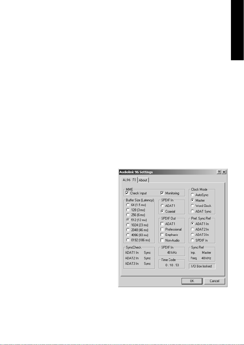
Windows
Configuring the Audiolink 96 system is done using its own settings dialog. The panel 'Settings' can be opened in two different ways:
• By clicking on the Nuendo symbol in the Taskbar's system tray
• By starting the 'Audiolink 96_Set' link from the Desktop
ENGLISH
The mixer of the Nuendo Audiolink 96 System (TotalMix) can be
opened in two different ways:
• By clicking on the mixer icon in the Taskbar's system tray
• By starting the 'Audiolink 96_Mix' link from the Desktop
NUENDO AUDIOLINK 96
English – 27
Page 28
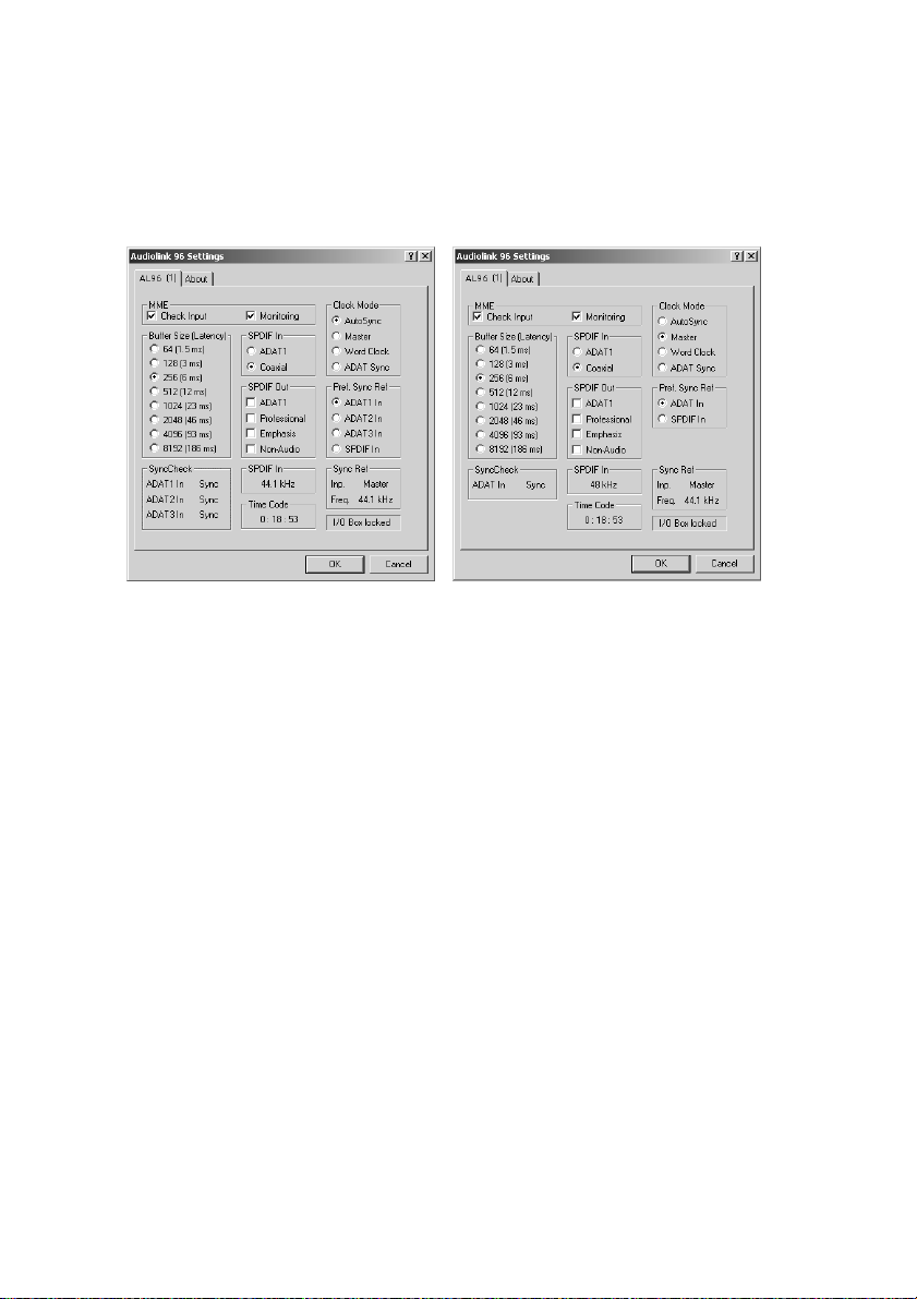
The Nuendo Audiolink 96’s hardware offers a number of helpful, well
thought-through practical functions and options which affect how the
card operates - it can be configured to suit many different requirements. The following is available in the 'Settings' dialog:
Digiset Settings Multiset Settings
• Input selection
• Output mode
• Output channel status
• Synchronization behaviour
• Input and output status display
• Time code display
Any changes made in the Settings dialog are applied immediately
- confirmation (e.g. by clicking on OK or exiting the dialog) is not required. However, settings should not be changed during playback or
recording if it can be avoided, as this can cause unwanted noises. Also,
please note that even in 'Stop' mode, several programs keep the recording and playback devices open, which means that any new settings might not be applied immediately.
The status displays at the bottom of the dialog box give the user precise information about the current status of the system, and the status
of all signals. ‘SyncCheck’ indicates whether there is a valid signal for
each input (‘Lock’ or ‘No Lock’), or if there is a valid and synchronous
signal (‘Sync’). The ‘Sync Ref’ display shows the input and frequency of
the current sync source.
NUENDO AUDIOLINK 96
English – 28
Page 29
'Time Code' displays time information received from the card’s ADAT
Sync In. This is convenient for checking whether the system is running
in time with the transmitting device (e.g. ADAT).
Buffer Size
The setting ‘Buffer Size’ determines the latency between incoming and
outgoing data, as well as affecting system stability (see section “13. Operation under ASIO 2.0” on page 41). We recommend selecting the
highest value here (8192 samples) – the board itself will still run comfortably. Under Windows MME, buffer sizes (and therefore latency) can
only be set within the audio application being used. Under GSIF the latency is fixed.
S/P-DIF In
Defines the input for the S/P-DIF signal. 'Coaxial' relates to the phono
socket, 'ADAT1' to the optical input ADAT1.
S/P-DIF Out
The S/P-DIF output signal is constantly available at the phono plug.
After selecting 'ADAT1'
it is also routed to the
optical output ADAT1.
For further details
about the settings ‘Professional’, ‘Emphasis’
and ‘Non-Audio’, please
refer to chapter 12.
ENGLISH
Digiset Settings
NUENDO AUDIOLINK 96
English – 29
Page 30
Clock Mode
The card can be configured to use the following clock sources:
external input signal as
pre-defined via Pref.
Sync Ref (AutoSync), internal clock (Master), or
external word clock
signal (Word Clock).
Pref. Sync Ref
Used to pre-select the
desired clock source. If
the selected source isn't
available the card will
change to the next available one. The currently
Multiset Settings
used clock source and sample rate is displayed in the SyncRef display.
MME
'Check Input' verifies the current input signal against the settings in the
record program. When de-activated a record will always be allowed,
even with non-valid input signals. 'Monitoring' activates the automatic
pass-through of the input signal when in record mode. Both settings
are valid for MME only.
I/O-Box State
This display shows the current state of the I/O-box:
I/O Box error I/O-box not connected or missing power.
I/O Box detected The interface has found a I/O-box and tries to load the firmware.
I/O Box locked Communication between interface and I/O-box ok.
NUENDO AUDIOLINK 96
English – 30
Page 31

9.2 Clock Modes - Synchronization
In the digital world, all devices are either the ‘Master’ (clock source) or a
‘Slave’ synchronized to the master. Whenever several devices are linked
within a system, there must always be a single master clock. The Nuendo Audiolink 96’s intelligent clock control is very user-friendly, being
able to switch between clock modes automatically. Selecting 'AutoSync' will activate this mode.
In AutoSync mode, the system constantly scans all digital inputs for a
valid signal. If this signal corresponds to the current playback sample
rate, the card switches from the internal quartz (Sync Ref displays 'Internal') to a clock generated from the input signal (Sync Ref displays 'S/PDIF' or 'ADATx'). This allows on-the-fly recording, even during playback,
without having to synchronize the card to the input signal first. It also
allows immediate playback at any sample rate without having to reconfigure the card.
AutoSync guarantees that normal record and record-while-play will always work correctly. In certain cases however, e.g. when the inputs and
outputs of a DAT machine are connected directly to the Nuendo
Audiolink 96, AutoSync causes feedback in the digital carrier, so synchronization breaks down. To remedy this, switch the Audiolink 96’s
clock mode over to 'Master'.
ENGLISH
❐
Remember that a digital system can only have one master! If the Audiolink
96’s clock mode is set to 'Master', all other devices must be set to ‘Slave’.
NUENDO AUDIOLINK 96
English – 31
Page 32
All the ADAT optical
inputs in the Nuendo Audiolink 96
as well as the S/PDIF input will work
simultaneously. Because there is no input selector
however, the
Audiolink 96 has to
be told which of the
signals is the sync
reference (a digital
device can only be
clocked from a sin-
gle source). This is
why the system has been equipped with automatic clock source selection, which adopts the first available input with a valid digital signal as
the clock reference input. The input currently used as sync reference is
shown in the 'Sync Ref' status field, together with the current sample
frequency.
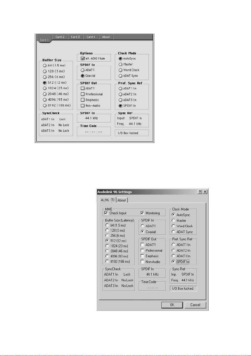
Via 'Pref Sync Ref' (preferred synchronization
reference) a preferred
input can be defined.
As long as the card sees
a valid signal there, this
input will be designated as the sync
source, otherwise the
other inputs will be
scanned in turn. If none
of the inputs are receiving a valid signal, the
card automatically
switches clock mode to
‘Master’.
NUENDO AUDIOLINK 96
English – 32
Page 33
To cope with some situations which may arise in studio practice, setting ‘Pref Sync Ref’ is essential. One example: An ADAT recorder is connected to the ADAT1 input (ADAT1 immediately becomes the sync
source) and a CD player is connected to the S/P-DIF input. Try recording a few samples from the CD and you will be disappointed. Few CD
players can be synchronized. The samples will inevitably be corrupted,
because the signal from the CD player is read with the (wrong) clock
from the ADAT i.e. out of sync. In this case, 'Pref Sync Ref' should be
temporarily set to S/P-DIF (see picture above).
If several digital devices are to be used simultaneously in a system, they
not only have to operate with the same sample frequency but also be
synchronous with each other. This is why digital systems always need a
single device defined as ‘master’, which sends the same clock signal to
all the other (‘slave’) devices. The SyncCheck technology enables an
easy to use check and display of the current clock status. The ‘SyncCheck’ field indicates whether no signal (‘No Lock’), a valid signal
(‘Lock’) or a valid and synchronous signal (‘Sync’) is present at each of
the three ADAT optical inputs. The ‘Sync Ref’ display shows the current
sync source’s input and frequency.
In practice, SyncCheck provides the user with an easy way of checking
whether all digital devices connected to the system are properly configured. With SyncCheck, finally anyone can master this common
source of error, previously one of the most complex issues in the digital
studio world.
ENGLISH
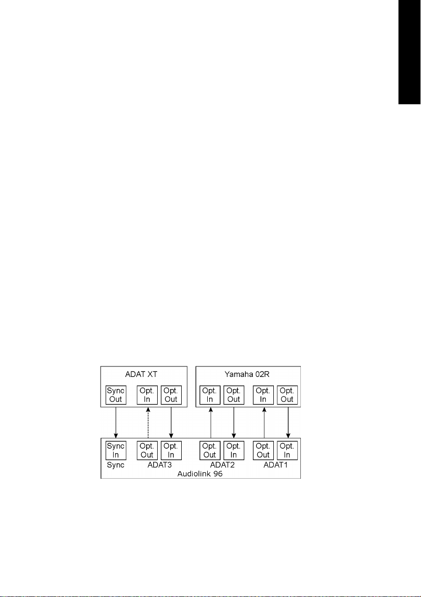
An example to illustrate this: The ADAT1 and ADAT2 inputs are receiving signals from a digital mixing desk that has been set to clock mode
'Internal' or 'Master'. An ADAT recorder is connected to the ADAT3 input. The Nuendo Audiolink 96 is set to AutoSync mode. As expected,
NUENDO AUDIOLINK 96
English – 33
Page 34

SyncCheck shows that the ADAT1 and ADAT2 inputs are in sync (as
they are driven by the same clock from the mixing desk), but shows
‘Lock’ instead of 'Sync' for the ADAT3 input. Because the ADAT recorder
is not receiving any signals from Audiolink 96 or from the mixer, it will
generate its own clock at a rate which is (almost) the same as the sample frequency of the mixing desk - but not identical. Remedy: To drive
the ADAT recorder from its digital input, set it to slave mode (DIG), and
connect the input to the Audiolink 96’s ADAT3 output. The Nuendo
Audiolink 96 is already in sync with the mixing desk, so it will send an
identical (synchronous) signal to ADAT3 out. The ADAT recorder will
lock onto this, its output will also be in sync. The signal from the ADAT
recorder is now fully in sync with the signals from the mixing desk.
Thanks to its AutoSync technique and a lightning fast PLL, the
Audiolink 96 is not only capable of handling standard frequencies, but
also any sample rate between 25 and 105 kHz. The input selected in
'Pref Sync Ref' serves as synchronization source. If word clock input is
selected (clock mode 'Word Clock'), this will serve as the synchronization source, allowing any sample frequency between 25 kHz and 56
kHz in varispeed operation.
The current sample frequency at the S/P-DIF input (displayed in the ‘S/
P-DIF In’ field) is useful for troubleshooting and checking the configuration of all connected digital devices. If an input without a valid signal
(or a faulty one) is selected, ‘No Lock’ will appear. In varispeed mode, or
if the sample frequency is way out of tune, ‘Lock’ is displayed. The Sync
state of the S/P-DIF signal is shown by a blinking (locked) or constantly
lit (Sync) input LED on the front of the Digiset.
At 88.2 or 96 kHz: If one of the ADAT inputs has been selected in ‘Pref
Sync Ref’, the sample frequency shown in the ‘S/P-DIF In’ field differs
from the one shown in ‘Sync Ref’. The card automatically switches to its
Sample Split mode here, because ADAT optical inputs and outputs are
only specified up to 48 kHz. Data from/to a single input/output is
spread over two channels, the internal frequency stays at 44.1 or 48
kHz. In such cases, the ADAT sample frequency is only half the S/P-DIF
frequency.
NUENDO AUDIOLINK 96
English – 34
Page 35

9.3 Changing the Jumper Settings – Multiset
The Multiset has internal jumpers, which allow to change input sensitivity and output level per channel. More information on these settings
can be found in chapter 8.5 and 8.6.
❐
Please note that those jumpers are not meant to be changed every day.
They should be changed when the unit is operated for the first time, so that
it matches the Studio's operating level. Only change them if it is really neccessary. The factory default +4 dBu will in most cases offer perfect results.
To change the jumper settings the Multiset must be opened. Consult
an experienced technician if you are unsure of how to do this. Please
follow the instructions below.
1. Remove all jacks and cables from the Multiset.
2. Loosen and remove both screws of the ADAT Sync D-sub socket.
3. Use a screwdriver (Phillips 1) to remove the 6 screws on the cover of the
Multiset, so that the cover can be taken off.
4. Place the device with the front panel in front of you. Lift the cover at the
front by about one centimeter (0.5 inches). Then pull the cover slowly
about 2 centimeters (1 inch) towards you. When doing so the TRS jacks
and the D-Sub socket will slide out of the rear panel. The cover is now not
attached to the rest of the housing and can be turned to the right.
Use this unique moment and have a look at the internal design of the Multiset.
On the right side of the lower printed circuit board (PCB) you can see the two
switching power supplies. They generate both 5 Volts (for the digital circuitry)
and ±13 Volts (for the analog circuitry) from nearly every possible input voltage. In the center you'll see the heart of the Multiset, the Xilinx FPGA. The analog circuitry and DA-converter for the headphone output is located on the right
of the FPGA. Left of the FPGA two Low Jitter PLLs can be seen. On the outer left
side you'll find 16 capacitors of the analog outputs and a 50-pin flat cable connector. The flat cable connects lower and upper board, the latter being the analog board, which is mounted on the inside of the cover.
ENGLISH
The analog board is covered by a thin metalized shield, preventing noise from
digital circuitry and flat cable being coupled into analog inputs and outputs.
Lift the shielding and take a look at the analog board.
NUENDO AUDIOLINK 96
English – 35
Page 36

But now back to the jumper settings.
5. Bend the flexible shield carefully upwards. You'll now see the analog
board with its 16 jumpers for level settings.
6. The jumpers controlling the sensitivity of the inputs are located directly
behind each TRS input jack. They allow three different settings: left (middle
plus left pin), right (middle plus right pin), and without jumper. If the device
is still placed with the front panel to the front, then left means +4 dBu
(factory default), right means Lo Gain, and without jumper means –10 dBV.
7. The jumpers controlling the output level are located on the other side of
the board, and are placed in pairs. The jumper nearer to the center of the
board is the one for an even channel (2/4/6/8). Again three settings are
possible: left (middle plus left pin), right (middle plus right pin), and without jumper. If the device is still placed with the front panel to the front,
then left means +4 dBu (factory default), right means Lo Gain, and without
jumper means –10 dBV.
A drawing showing the jumper position for each level setting is found
on the left side (underneath the flat cable) on the analog board.
❐
To prevent the loss of jumpers in –10 dBV mode, we recommend not to remove them completely, but to mount them at the outside of the jumper
(no connection to the center pin).
Now you are ready to re-assemble the Multiset.
8. Turn the cover to the left and move it back over the Multiset.
❐
Try to fold the flat cable the way it was when you opened the device. Otherwise, it may be difficult to close the housing again.
9. Move the cover so that it is placed 2 centimeters (1 inch) above the housing. Tilt the cover so that the jacks point to the holes in the rear panel.
Carefully slide the jacks into the holes by moving the cover away from
you. When inserted completely into the rear panel, the cover can now be
layed down.
10. Re-fit the 6 screws into the cover, and re-fit and tighten both screws of the
D-sub jack. That's it!
NUENDO AUDIOLINK 96
English – 36
Page 37

10. Word Clock
10.1 Technical Description and Usage
Correct interpretation of digital audio data is dependent upon a definite sample frequency. Signals can only be correctly processed or transferred between devices if these all share the same clock, otherwise
digital signals are misinterpreted, causing distortion, clicks/crackle and
even dropouts.
AES/EBU, S/P-DIF and ADAT are self-clocking, so an additional line for
word clock could be considered redundant. In practice however, using
several devices at the same time can cause problems. For example, if
devices are connected in a loop without there being a defined ‘master’
device, self-clocking may break down. Besides, the clocks of all devices
must be synchronized from a single source. Devices without S/P-DIF inputs (typically playback devices such as CD players) cannot be synchronized via self-clocking.
In digital studios, synchronization requirements can be met by connecting all devices to a central sync source. For instance, the master device could be a mixing desk, sending a reference signal - word clock - to
all other devices. However, this will only work if all the other devices
have word clock inputs (e.g. some professional CD players) allowing
them to run as slaves. This being the case, all devices will receive the
same clock signal, so there is no fundamental reason for sync problems
when they are connected together.
ENGLISH
10.2 Cables and Termination
Word clock signals are usually distributed in the form of a network, split
with BNC T-adapters and terminated with resistors. We recommend using off-the-shelf BNC cables to connect all devices, as this type of cable
is used for most computer networks. You will find all the necessary
components (T-adapters, terminators, cables) in most electronics and/
or computer stores.
To avoid voltage loss and reflections, both the cable itself and the terminating resistor should have an impedance of 75 Ohm. If the voltage
is too low, synchronization will fail. High frequency reflection effects
can cause both jitter and sync failure.
NUENDO AUDIOLINK 96
English – 37
Page 38

In practice, the situation has improved in recent years. The relatively low
frequency of word clock signals is not a problem for modern electronic
circuits. Because of the higher voltage, word clock networks are often
more stable and reliable if cables are not terminated at all. Also, 75 Ohm
cable is almost impossible to find these days. 50 Ohm cable is standard
– this will also work as long as the termination resistors are 75 Ohm.
The word clock input of the Nuendo Audiolink 96 is a high-impedance
type ensuring maximum flexibility, and is therefore not terminated. If
normal termination is necessary (e.g. because Nuendo Audiolink 96 is
the last device in the chain), simply connect a T-adapter to its BNC input jack, connect the cable supplying the word clock signal to one arm
of the T-adapter and terminate the other with a 75 Ohm resistor (as a
short BNC plug).
In case Nuendo Audiolink 96 resides within a chain of devices receiving
word clock, plug a T-adapter into Nuendo Audiolink 96’s BNC input jack
and the cable supplying the word clock signal to one end of the
adapter (as above), but connect the free end to the next device in the
chain via a further BNC cable. The last device in the chain should be terminated using another T-adapter and a terminator plug as described in
the previous paragraph.
10.3 General Operation
The green ‘Lock’ LED (Input State) will light up when the input sees a
valid word clock signal. Selecting ‘Word Clock’ in the ‘Clock Mode’ field
will switch clock control over to the word clock signal. As soon as there
is a valid signal at the BNC jack, 'Sync Ref' will display 'Word'. This message has the same function as the green ‘Lock’ LED, but appears on the
monitor, i.e. the user can check immediately whether a valid word clock
signal is present and is currently being used.
❐
The wordclock input and output as well as all ADAT ports only work in
Single Speed mode. At 96 kHz, the word clock output will therefore be a
48 kHz signal.
NUENDO AUDIOLINK 96
English – 38
Page 39

11. Using more than one Nuendo Audiolink 96
The current drivers support multiple interfaces and any combination of
I/O-boxes. Please note that (of course) only one ADAT Sync can be
used. Also all systems must be in sync, i.e. have to receive valid sync information (either via wordclock or using AutoSync).
12. Special Characteristics of the S/P-DIF Output
Apart from the audio data itself, digital signals in S/P-DIF or AES/EBU
format have a header containing channel status information. False
channel status is a common cause of malfunction. The Nuendo
Audiolink 96 ignores the received header and creates a totally new one
for the output signal.
❐
Note that in record or monitor modes, set emphasis bits will disappear.
Recordings originally done with emphasis should always be played back
with the emphasis bit set!
This can be done by selecting the 'Emphasis' switch in the Settings dialog ('S/P-DIF Out'). This setting is updated immediately, even during
playback. The Nuendo Audiolink 96’s new output header is optimized
for largest compatibility with other digital devices:
ENGLISH
• 32 kHz, 44.1 kHz, 48 kHz, 88.2 kHz or 96 kHz, depending on the current sample rate
• Audio use, Non-Audio
• No Copyright, Copy Permitted
• Format Consumer or Professional
• Category General, Generation not indicated
• 2-channel, No Emphasis or 50/15 µs
• Aux bits Audio Use
Professional AES/EBU equipment can be connected to the Nuendo
Audiolink 96 thanks to the transformer-balanced coaxial outputs, and
the ‘Professional’ format option with doubled output voltage. Output
cables should have the same pinout as those used for input (see section “8.1 Connections” on page 16), but with a male XLR plug instead of
a female one.
NUENDO AUDIOLINK 96
English – 39
Page 40

❐
Note that most consumer-orientated equipment (with optical or phono S/
P-DIF inputs) will only accept signals in ‘Consumer’ format!
The audio bit in the header can be set to 'Non-Audio'. This is necessary
when Dolby AC-3 encoded data is sent to external decoders (surroundsound receivers, television sets etc. with AC-3 digital inputs), as these
decoders would otherwise not recognize the data as AC-3.
NUENDO AUDIOLINK 96
English – 40
Page 41
13. Operation under ASIO 2.0
13.1 General
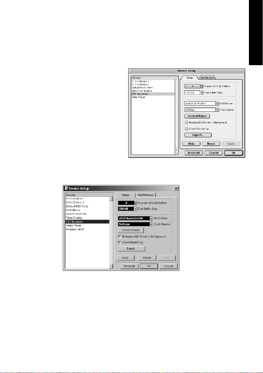
Start Nuendo and open
the ‘Device Setup’ dialog from the Device
menu. Select 'VST Multitrack' and make the desired settings.
If necessary, read the
corresponding sections of the Nuendo
documentation.
By clicking on the 'Control Panel' button, you
can open the Nuendo Audiolink 96 Settings dialog (see section “9. Configuring the Digiset or Multiset” on page 24).
Nuendo Audiolink 96
also allows simultaneous record and playback of S/P-DIF audio
data together with
record and playback in
ADAT format.
ENGLISH
Please note that the external S/P-DIF devices
have to be running in
sync, otherwise record-
ings will be corrupted.
Nuendo Audiolink 96 supports 'ASIO Direct Monitoring'.
When the sample frequency is set to 88.2 or 96 kHz, all the ADAT optical
inputs and outputs operate in Sample Split mode, so the number of
available channels is reduced 4 (Multiset) or 12 (Digiset), respectively.
NUENDO AUDIOLINK 96
English – 41
Page 42

13.2 Performance
A very common problem is insufficient hard disk performance. If the
first track is missing while recording
multiple tracks, or the error mes-
sage ‘Audio: Record Error’ appears,
the disk sub-system is too slow, i.e. it is unable to write the audio data
to the disk quickly enough. The problem can almost always be remedied by changing ‘Disk Block Buffer Size’ from the default 64kB to
256kB.
This is especially true if you want to
record more than 12 tracks at the
same time. 26 tracks are only possible after changing ‘Disk Block Buffer
Size’ to 256kB (depending on your
computer). Please note that these parameters are only updated after
clicking on ‘Apply’.
The heyday of (expensive) SCSI hard disks in high-speed audio workstations is over. Today’s cheap high-capacity EIDE disks allow continuous
transfer rates of well over 5 MB per second. In practical terms, this is
more than enough to record up to 24 simultaneous tracks using Nuendo and Nuendo Audiolink 96!
Windows However, the hard disks have to work using the Windows 98 Busmaster
drivers. To activate the EIDE Busmaster mode, open the Device Manager
(Control Panel/System). Double-click on ‘Disk drives’, then on the required
hard disk(s). Select ‘DMA’ in the Properties dialog, then restart Windows.
The Buffer Size value in Nuendo Audiolink 96’s Settings dialog determines the latency (in this case the delay) between the audio application and the Audiolink 96 as well as general system stability. The higher
the value, the more tracks can be recorded and played back simultaneously and the longer the system takes to react. At the given maximum of about 0.2 seconds, you will not notice much delay at all - the
system will still respond quickly and smoothly.
Windows Present systems are unable to use the 1.5 ms mode without audible clicks.
Current PCs can handle 3 ms. For optimum reliability we recommend setting the highest latency possible, 182 ms.
NUENDO AUDIOLINK 96
English – 42
Page 43

13.3 Synchronization
On the Transport menu,
select ‘Synchronization
Setup’ to open the corresponding dialog. In the
dialog’s Time code source
section, activate ‘ASIO Positioning Protocol’ by
clicking on the respective
radio button. Activate
Sync mode with a single
mouse click on the Online
button on Nuendo’s
Transport bar.
ENGLISH
To achieve sample-accuracy between the ADAT
recorder and Nuendo
Audiolink 96 while running Nuendo, connect
the ADAT sync output
with the 9-pin D-type
sync input of the
Audiolink 96. The ‘Time
Code’ field in the Settings
dialog should now show
the same position as the
ADAT recorder.
If synchronization is not working i.e. Nuendo does not respond when
the ADAT is set to ‘Play’, please try the following:
• Check the cables.
• Switch Online off and on again (in Nuendo’s transport panel).
• Click on the ‘Reset’ button in the ‘Reset Devices’ dialog that you can open from
the ‘Devices’ menu.
• Switch on the ADAT recorder(s) before starting Nuendo.
• Use the BRC as Master and send its word clock to all other devices.
• Use the Clock Mode ADAT Sync.
NUENDO AUDIOLINK 96
English – 43
Page 44

13.4 Known Problems
Dropouts, noise and crackling will occur if your computer has insufficient CPU power or insufficiient PCI bus transfer rates. We also recommend to deactivate all PlugIns to verify that these are not the reason for
such effects.
Windows Unfortunately some newer UltraATA66 and UltraATA100 hard disk con-
trollers (also Raid controllers) appear not to follow the PCI specifications.
To achieve the highest throughput they hog the PCI bus, even in their default setting. Thus when working with low latencies heavy drop outs
(clicks) are heard. Try to solve this problem by changing the default setting
of the controller (for example by reducing the 'PCI Bus Utilization').
Another common source of trouble is incorrect synchronization. ASIO
does not support asynchronous operation, which means that the input
and output signals must not only have the same sample frequency, but
they must also be in sync. All devices connected to the Nuendo
Audiolink 96 must be properly configured for Full Duplex operation. As
long as SyncCheck (in the Settings dialog) only displays 'Lock' instead
of 'Sync', the devices have not been set up properly!
NUENDO AUDIOLINK 96
English – 44
Page 45

14. TotalMix: Routing and Monitoring
The Nuendo Audiolink 96 system includes a powerful digital real-time
mixer. The unique TotalMix technology allows for nearly unlimited mixing and routing with all inputs and playback channels simultaneously.
Here are some typical applications for TotalMix:
• Setting up delay-free submixes (headphone mixes)
• Unlimited routing of inputs and outputs (free utilisation, patchbay function)
• Distributing signals to several outputs at a time
• Simultaneous playback of different programs over only one stereo channel
• Mixing of the input signal to the playback signal (complete ASIO Direct Moni-
toring)
• Integration of external devices (effects etc). in real-time
• Mixdown of three ADAT inputs to one (realizing two additional inputs)
On page 67 you’ll find a block diagram of the TotalMix mixer of the
Digiset. It can help to understand the basic signal flow and routing. It
shows that the record signal always stays un-altered, but can be passed
on as often as desired, even with different levels. The level meters of inputs and playback channels are connected pre-fader (due to the enormous routing capabilities). The level meters of the hardware’s outputs
are connected post-fader.
ENGLISH
Macintosh To call up the mixer start the program Nuendo Audiolink 96 TotalMix.
14.1 Interface Elements
The visible design of the mixer is mainly determined by the architecture of the Audiolink 96 system:
• Upper row: hardware inputs. The level shown is that of the input signal, i.e.
Fader independent. Per fader and routing window, any input channel can be
routed and mixed to any hardware output (third row).
• Middle row: playback channels (playback tracks of the software). Per fader and
routing window, any playback channel can be routed and mixed to any hardware output (third row).
• Lower row: hardware outputs. Because they refer to the output of a subgroup,
the level can only be attenuated here (in order to avoid overloads), routing is
not possible. This row has two additional channels, the analog outputs.
NUENDO AUDIOLINK 96
English – 45
Page 46

Every single channel has several elements:
Input and playback channels each have a mute and solo button.
Below each there is the panpot in the form of an indicator bar
(L/R) in order to save space.
In the window below this, the present level is displayed in RMS
or Peak, updated about every half a second. Overs are indicated here by an additional red dot.
This is followed by the fader with a levelmeter. The meter
shows both peak values (zero attack, 1 sample is enough for
displaying full scale) by means of a yellow line and mathematically correct RMS values by means of a green bar. The RMS display has a relatively slow time constant, so that it shows the
average loudness quite well.
Below the fader the current gain and panorama values are
shown.
The white area shows the channel name, the black area shows the cur-
rent routing target.
14.2 TotalMix – Introduction
In the following chapters we will explain all functions of the user interface step by step. When launching TotalMix, the last settings are recalled automatically. When executing the application for the first time,
a default file is loaded, sending all playback tracks 1:1 to the corresponding hardware outputs with 0 dB gain. The faders in the top row
are set to maximum attenuation (called m.a. in the following), so there
is no monitoring of the input channels.
NUENDO AUDIOLINK 96
English – 46
Page 47

We will now create a small submix for the analog
headphone output. Please start a multitrack playback and connect your headphones to the analog
output. In playback channel 1 (labeled 'Out 1'), click
onto the routing window below the label. A list
pops up, showing a checkmark in front of '1+2'.
Click onto 'Analog'. The list disappears, the routing
window no longer shows '1+2', but 'Analog'. Now
move the fader with the mouse. As soon as the
fader value is unequal m.a., the present state is being stored and routing is activated. Move the fader
button to around 0 dB. The present gain value is
displayed below the fader in green letters. In the
lower row, on channels 27 and 28 (AN.L. and AN.R.),
you can also see the level of what you are hearing
in the phones. The level meter of the hardware output shows the outgoing level. Click into the area
above the fader and drag the mouse in order to set
the panorama, in this case the routing between
channels 27 and 28. The present pan value is also
being displayed below the fader.
ENGLISH
Please carry out the same steps for 'Out 2' now, in order to route it to
the analog output as well.
Often signals are stereo, i.e. a pair of two channels. It is therefore helpful
to be able to make the routing settings for two channels at once. Press
the [Ctrl]-key and click into the routing window of 'Out 3' with the key
pressed. The routing list pops up with a checkmark at '3+4'. Click onto
'Analog'. Now, channel 4 has already been set to 'Analog' as well.
When you want to set the fader to exactly 0 dB, this can be difficult, depending on the mouse configuration. Move the fader close to the 0 position and press the [Shift]-key. This activates the fine-mode, which
stretches the mouse movements by a factor of 8. In this mode, a gain
setting accurate to 0.1 dB is no problem at all.
Please set 'Out 4' to a gain of around -20 dB and the pan close to center.
Click onto the routing window. You'll now see two checkmarks, one at
'3+4', the other one at 'Analog'. Click onto 'S/P-DIF'. The window disappears, fader and panpot jump to their initial values and the signal can
NUENDO AUDIOLINK 96
English – 47
Page 48

be routed to the S/P-DIF output. You can continue until all entries have
got a checkmark, i.e. you can send the signal to all outputs simultaneously. This is one of several differences to the Nuendo mixer, which
does not allow for multiple selections.
You will certainly have noticed that the headphone mix did not change
while you were routing the channel to other outputs and setting different gain values. With all analog and most digital mixing desks, the fader
setting would affect the level for every routed bus - not so for TotalMix.
TotalMix allows for setting all fader values individually. Therefore the
faders and the panpots jump to the appropriate setting as soon as another routing is chosen.
The checkmarks are un-checked by moving the fader to m.a. This setting deactivates the routing…why route if there is no level? Click onto
'3+4' in the routing window, pull the fader down, open the routing window again – the checkmark is gone.
14.3 Submix View
Such a wide range of possibilities makes it difficult to keep an overview
because practically all hardware outputs can be used for different submixes, as shown. And when opening the routing windows you might
see lots of checkmarks making it very difficult to see how the signals
come together and where. This problem is removed by the view mode
'Submix'. In this mode, all routing windows jump to the routing pair
currently selected. Here you see immediately which channels and
which fader and pan settings make a submix (for example 'Analog').
14.4 Mute and Solo
Mute works pre-fader, thus mutes all active routings of the channel. As
soon as any Mute button is pressed, the Master Mute button lights up
in the quick access area. It can switch all selected mutes off and on
again. You can comfortably make mute groups to activate and deactivate this way.
The same holds true for the Solo and the Master Solo buttons. Solo is
working as a solo-in-place. As soon as one Solo button is pressed, all
other Mute buttons are activated and light up. But TotalMix would not
be an Intelligent Audio Solution if it didn't behave as you'd expect from
NUENDO AUDIOLINK 96
English – 48
Page 49

a mixing console. If you, for instance, mute 'Out 1' to 'Out 4' and press
Solo for 'Out 5', of course all Mute buttons will light up. If you deactivate Solo, the Mute buttons for 'Out 1' to 'Out 4' light up as before. And
if you chose Solo for a channel of this Mute group, mute will be deactivated, but immediately activated again, if Solo is released.
14.5 Hotkeys
TotalMix knows only a few but very effective key combinations that
make setting the mixer up considerably easier and faster. The [Shift]key for the fine-mode for faders and panpots has already been mentioned. But the [Ctrl]-key can do far more than changing the routing for
channel pairs:
• Clicking anywhere into the fader area with the [Ctrl]-key pressed sets the fader
to 0 dB, -6 dB for the hardware outputs.
• Clicking anywhere into the pan area with the [Ctrl]-key pressed sets the panorama to <C> meaning 'Center'.
Windows The faders can also be moved in pairs, corresponding to the stereo-routing
settings.
Macintosh The faders can also be moved in pairs, corresponding to the stereo pairs.
ENGLISH
This can be achieved by pressing the [Alt]-key and is especially comfortable when setting the S/P-DIF and analog output level.
Macintosh Even the Panoramas can be operated with [Alt], from stereo through mono
to inversed channels.
At the same time, TotalMix also supports combinations of these keys. If
you press [Ctrl] and [Alt] at the same time, clicking with the mouse
makes both faders jump to 0 dB, and they can be set in pairs by [Shift][Alt] in fine-mode.
Also very useful: the faders have two mouse areas. The first area is the
fader button, which can be grabbed at any place without changing the
position. This avoids unwanted changes when clicking onto it. The second area is the whole fader setting area. Clicking into this area makes
the fader jump to the mouse pointer position at once. If you want to set
several faders to m.a. for instance, it is sufficient to click onto the lower
end of the fader path. Which happens in pairs with the [Alt]-key pressed.
For more hotkeys see the section “14.7 Level Meter” on page 51.
NUENDO AUDIOLINK 96
English – 49
Page 50
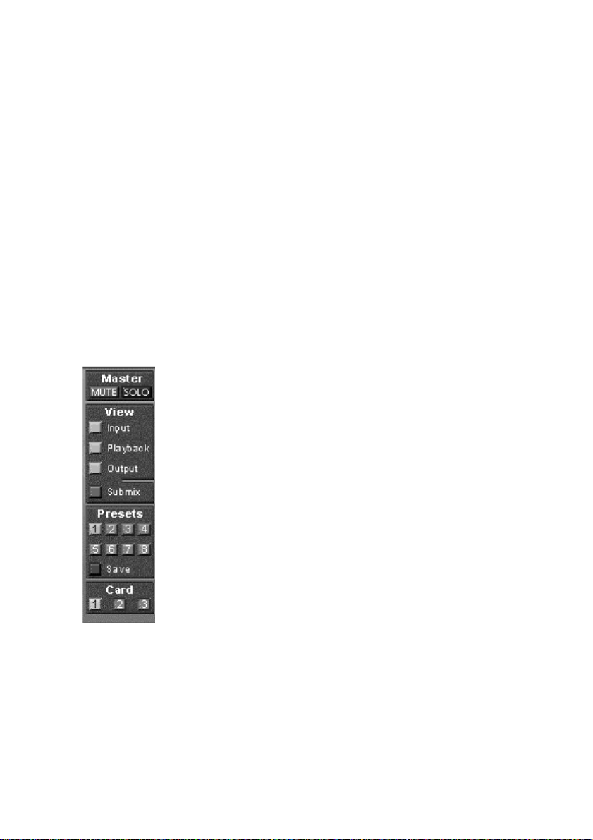
14.6 The Quick Access Panel
This section includes additional options, further improving the handling of TotalMix. The Master button for Mute and Solo has already
been described, it allows group-based working with these functions.
In the View section the single rows can be made visible or invisible. If
the inputs are not needed for a pristine playback mix, the top row is
hidden after a click on the input button. If the hardware outputs don't
interest you either, the visible interface can thus be reduced to the
playback channels to save space. All combinations are possible.
Submix sets all routing windows to the same selection as described before. Deactivating Submix automatically recalls the previous view.
The mixer can also be made smaller horizontally and scrolled. TotalMix
can be made substantially smaller and space-saving on the desktop/
screen, if you have to monitor or set only a few channels or level meters.
The Presets are one of the mightiest and most useful
features of TotalMix. There are eight buttons corresponding to eight preset files. These contain the complete mixer state. Just try it: all faders and other settings
follow the changing of preset(s) in real-time, at a single
mouse click. The Save button allows storing the present
settings in the current preset. You can change back and
forth between a signal distribution, complete input
monitoring and various submixes without any problem.
If any parameter is altered after loading a preset (e.g.
moving a fader), the preset display flashes indicating
that something was changed while still showing which
state the present mix is based on.
If no preset button is lit, another preset had been loaded
via the File menu and 'Open file'. Mixer settings can of
course be saved the usual way, and with long file names.
Up to three Nuendo Audiolink 96 systems can be used simultaneously.
The Card buttons switch between the systems. Systems, because card 1
can be a Digiset, but card 2 can also be a Multiset.
NUENDO AUDIOLINK 96
English – 50
Page 51
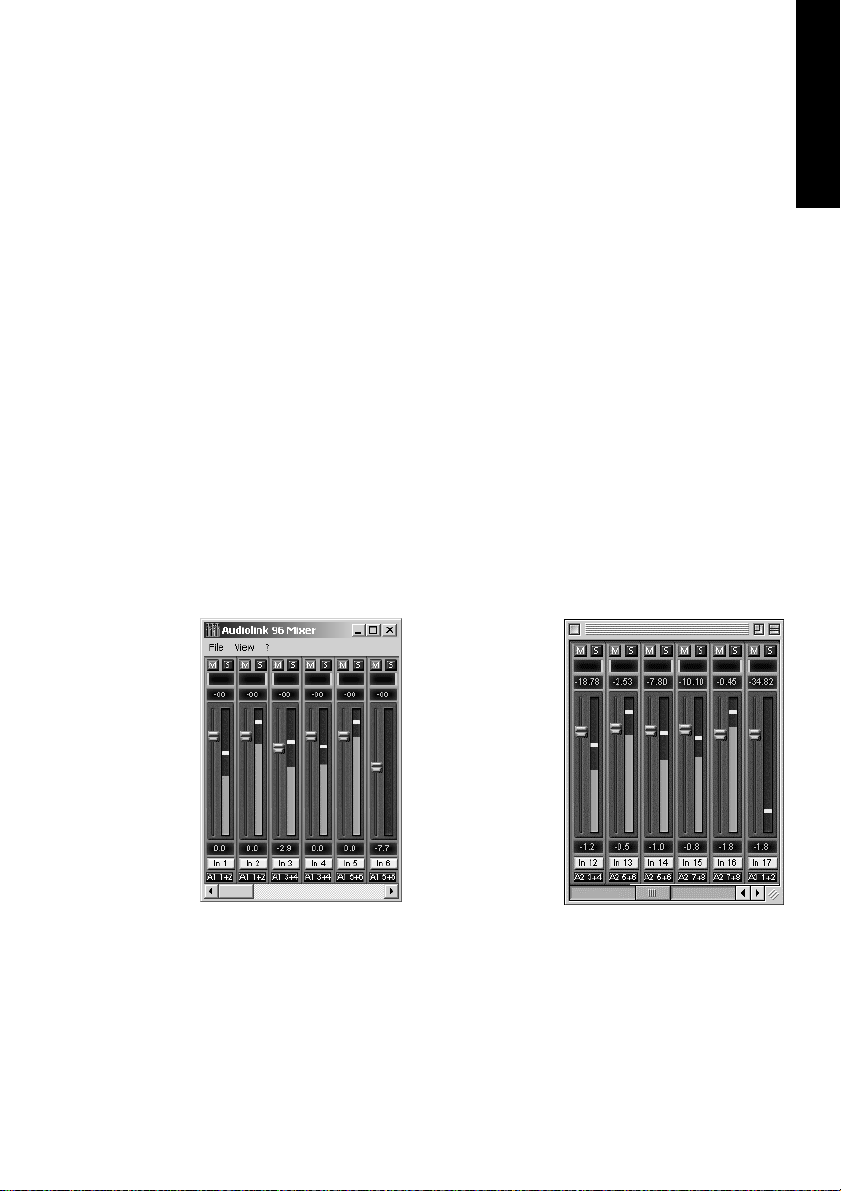
The number of ADAT channels is reduced to half automatically when
chosing double speed operation (88.2 or 96 kHz). The display is adjusted accordingly, but the fader settings remain stored.
14.7 Level Meter
Nuendo Audiolink 96’s calculation of the peak and RMS levels is performed in hardware, in order to be capable of using them independent
of the software in use, and to significantly reduce the CPU load.
The level meters integrated in TotalMix – for their size alone – cannot
be compared with a pure meter bridge (available later). Nevertheless,
they include many useful functions.
Peak and RMS is displayed for every channel. Several option are available, either through 'Level Meter Setup' or via hotkeys:
• Display range 40 or 60 dB (hotkey 4 or 6)
• Peak Hold time adjustable
• Numerical display selectable either Peak or RMS (Hotkey P or R)
• Number of consecutive samples for Overload display (1 to 15)
• RMS display absolute or relative to 0 dBFS (Hotkey 0 or 3)
The latter is a
point often
overlooked, but
nonetheless important. RMS
shows 3 dB less
for sine signals.
This is mathematically correct, but not
very reasonable for a level
meter. Therefore, we corrected the RMS display by 3 dB, a full scale sine signal shows
both 0 dBFS Peak and RMS. This setting also yields directly readable signal-to-noise values, while other applications (like WaveLab) will show a
value 3 dB better than it really is (because the reference is not 0 dB, but
-3 dB).
ENGLISH
NUENDO AUDIOLINK 96
English – 51
Page 52

The value displayed in the text field is independent of the setting 40/60
dB, it represents the full 24 bit range of the RMS measurement, thus
making possible an SNR measurement 'RMS unweighted', which you
would otherwise need extremely expensive measurement devices for.
An ADI-8 DS connected to the Digiset will therefore show around -113
dB on all 8 channels.
This level display will constantly bring the reduced dynamic range of
your equipment, maybe of the whole studio, in front of your eyes. Nice
to have everything 24 bit - but still noise and hum everywhere in the
range around -90 dB or worse…sorry, but this is hard reality. The upside about it is that TotalMix allows for constantly monitoring the signal quality without effort. Thus it can be a valuable tool for sound optimization and error removal in the studio.
❐
Measuring SNR (Signal to Noise) requires to press R (for RMS) and 3 (for referring to 0 dBFS, a full scale signal). The text display will then show the
same value as an expensive measurement system, when measuring ‘RMS
unweighted’.
15. Notes on using Laptops and CardBus
Windows
The Audiolink 96 system uses the notebook’s PCMCIA type II port as
CardBus interface. Compared to a PC-Card, which only has access to
the outdated ISA-bus, CardBus is a 32 bit PCI interface. Like with a desktop system it’s not possible to remove a PCI device while in operation.
First the operating system has to receive a ‚removal request’, then the
device has to be stopped. Finally the card can be pulled out of the PCMCIA slot.
To remove the hardware, click on the green
arrow symbol in the systray. It is possible to
stop the Audiolink 96 directly, or to first call up the info dialog by double clicking the symbol, and then stopping it.
NUENDO AUDIOLINK 96
English – 52
Page 53

When inserting the CardBus card it usually will be detected automatically by the notebook hardware and then Windows. A double beep signals detection and removal. In rare cases detection will fail. If so, simply
remove the card and insert it again. On one of the tested notebooks the
card was never activated at Windows boot, but only when plugged in
manually. The problem vanished after a fresh install of Windows ME.
The Nuendo Audiolink 96 system was tested thoroughly on several notebooks. Basically our CardBus card operates with any notebook we have
tested. But there were some significant performance differences, and
some laptops suffered from a very low data transfer rate of the PC-Card
controller. Detailed information on this can be found under
http://www.rme-audio.com/english/techinfo/index.htm.
The mobile operation of the Audiolink 96 system can cause problems.
Explanations and solutions on digital noise, ground loops, headphone
operation and Line Out wiring, power supplies and the mobile operation with battery can be found on the website
http://www.rme-audio.com/english/techinfo/index.htm.
The hardware of a notebook differs in many points from that of a desktop computer – sometimes…Detailed information on all components,
from CPU to the display, can be found on the website
http://www.rme-audio.com/english/techinfo/index.htm.
ENGLISH
Why does your notebook behave completely different from your desktop computer? And how can you still change it for good performance
(not only audio performance)? Find answers to these and many other
questions about software tuning and installation, clicks under Win9x,
the usage of the low latency solution Windows 2000, and the optimization of the memory bandwidth, under
http://www.rme-audio.com/english/techinfo/index.htm.
Macintosh
The Audiolink 96 system uses the notebook’s PCMCIA type II port as
CardBus interface. Compared to a PC-Card, which only has access to
the outdated ISA-bus, CardBus is a 32 bit PCI interface. When inserting
the CardBus card it usually is detected automatically by the notebook
hardware and then by the MacOS. An icon labeled 'Audiolink 96' will
appear on the desktop.
NUENDO AUDIOLINK 96
English – 53
Page 54

Like with a desktop computer it is not possible to remove a PCI device
while in operation. First the operating system has to receive a 'removal
request’, then the device has to be stopped.
This procedure prooves to be very simple on the MacOS: just drag the
'Audiolink 96' icon in the trash can. The MacOS internally de-installs the
CardBus card and switches off power (the red Host LED begins to blink).
The card can now be pulled out of the PCMCIA slot.
The Nuendo Audiolink 96 system was tested thoroughly on several
notebooks. We did not find any compatibility problems with older G3
Powerbooks or the latest Titanium. The performance was good and allowed to use latencies down to 1.5 ms.
The mobile operation of the Audiolink 96 system can cause problems.
Explanations and solutions on digital noise, ground loops, headphone
operation and Line Out wiring, power supplies and the mobile operation with battery can be found on the website
http://www.rme-audio.com/english/techinfo/index.htm.
The hardware of a notebook differs in many points from that of a desktop computer – sometimes…Detailed information on all components,
from CPU to the display, can be found on the website
http://www.rme-audio.com/english/techinfo/index.htm.
Although the information on the website refers to IBM-compatible
computers, it might still be interesting for Mac users.
NUENDO AUDIOLINK 96
English – 54
Page 55

16. Problems and Solutions
ENGLISH
Problem Operating
System
The ADAT timecode is not in sync
ADAT timecode is
running, but Nuendo does not
start 'Play' automatically
The input signal
cannot be monitored in real-time
The first 8 channels
don’t seem to work
Low Latency ASIO
operation under
Windows 2000 on
single CPU systems:
The performance
with emagic's
Logic is poor
All The tape is formatted to 48 kHz, but played back at
All The input displayed in ‘Sync Ref’ is not in sync mode.
All ASIO Direct Monitoring has not been enabled, and/or
All S/P-DIF output has been switched to ADAT1. This
Windows To use ASIO at lowest latencies under Windows 2000
Macintosh Ensure that 'Alt.ASIO Mode' is checked (Nuendo
Solution
44.1 kHz (Pitch). This 'Blackface' problem cannot be
solved in a satisfactory way.
Sync mode is essential, because ADAT’s so-called time
code is really a sample position, and is therefore only
valid for synchronous audio data.
Sync is displayed (referring to the card’s clock), but
the incoming data is not in sync with the sample position received at the ADAT Sync In. Then Nuendo does
not start. Set ‘Pref. Sync Ref’ to the input corresponding to the received ADAT Sync signal.
Sync mode wasn't activated (button in the transport
panel), or ASIO 2.0 has not been chosen as the SMPTE
sync source.
monitoring has been globally disabled.
means that the first ADAT output device, and therefore the first 8 channels in the ASIO application, are no
longer available. All channels and their assignments
still exist, but the optical transmitter has been disconnected from the ADAT and is now fed from the S/PDIF output (channels 25 and 26).
even when only having one CPU, the system performance has to be optimized for background tasks. Go
to Control Panel/System/Advanced/Performance Options. Change the default 'Applications' to 'Background tasks'. The lowest usable latency will drop
from 23 ms to around 3 ms. This is no issue when using dual CPU systems.
Audiolink 96 Settings, Options). This setting can be
changed on the fly.
NUENDO AUDIOLINK 96
English – 55
Page 56

Problem Operating
System
The following
symptoms are typical for PCI related
problems:
When booting the
control panels are
displayed too big,
or spread across
the whole screen.
Software or OS
crash as soon as
the card is used.
The dialog 'New
hardware component found’ does
not appear:
Macintosh These problems were reported with older computers
Windows Check whether the CardBus card is completely in-
Solution
(prior to G3). They can be solved in most cases by simply using a different slot, or by exchanging slots with
other PCI cards (like SCSI controllers or graphics
cards).
serted into the PCMCIA slot, or the PCI interface is correctly inserted in the PCI slot.
The card and drivers have been installed correctly,
but playback does
not work:
The card and drivers have been installed correctly,
but playback does
not work:
Playback works,
but record doesn’t:
Macintosh Check whether the Nuendo Audiolink 96 has been se-
lected as current ASIO device.
Windows Check whether the Nuendo Audiolink 96 appears in
the Device Manager. If the ' Nuendo Audiolink 96’ device has a yellow exclamation mark, then there is an
address or interrupt conflict.
Even if there is no yellow exclamation mark, it is worth
checking the ‘Resources’ tab anyway.
Check whether the Nuendo Audiolink 96 has been selected as current ASIO device.
All Check that there is a valid signal at the input. If so, the
current sample frequency is displayed in the Settings
dialog.
Check whether the Nuendo Audiolink 96 has been selected as recording device in the audio application.
Check whether the sample frequency set in the audio
application (‘Recording properties’ or similar)
matches the input signal.
Check that cables/devices have not been connected
in a closed loop. If so, set the systems’s clock mode to
‘Master’.
NUENDO AUDIOLINK 96
English – 56
Page 57

ENGLISH
Problem Operating
System
Crackle during
record or playback:
Crackle during
record or playback:
The computer
crashes whenever
the Nuendo
Audiolink 96 is accessed:
32 kHz files will not
play back:
All Increase the number and size of buffers in the ‘Set-
Windows Activate Busmaster mode for the hard disks (see sec-
Windows If your graphics board is an older Matrox Mystique or
All Nuendo Audiolink 96 does not have an internal 32
Solution
tings’ dialog or in the application.
Try different cables (coaxial or optical) to rule out any
defects here.
Check that cables/devices have not been connected
in a closed loop. If so, set the system’s clock mode to
‘Master’.
Increase the buffer size of the hard disk cache.
tion “13.2 Performance” on page 42).
In case of a recently done BIOS update of the motherboard: Propably 'Load BIOS Defaults' was loaded instead of 'Load Setup Defaults'. This sets the 'PCI
Latency Timer' to 0 (default: 32).
uses a ‘968’ S3 chip, there could be a memory allocation error. Change the memory area allocated to the
Nuendo Audiolink 96 via /Resources/Change Setting.
Detailed information on this subject can be found on
the Internet. Please point your browser to http://
www.rme-audio.com/english/techinfo/index.htm.
kHz clock, as this frequency is not covered by the
ADAT standard. However, you can record and playback via S/P-DIF if the card is clocked from an external
device i.e. AutoSync or Word Clock are active, and fed
S/P-DIF or equivalent word clock signal is 32 kHz.
NUENDO AUDIOLINK 96
English – 57
Page 58

17. Software and Hardware Compatibility
Nuendo Audiolink 96 is fully compatible with PCI bus version 2.1.
Nuendo Audiolink 96 is fully compatible with ASIO 1.0 and ASIO 2.0.
As far as we are aware, the Nuendo Audiolink 96 digital inputs and out-
puts are fully compatible with all devices with S/P-DIF or AES/EBU interfaces.
18. Installation problems (Windows)
The card is normally found in the Device Manager (>Settings/Control
Panel/System<) in the category 'Sound-, Video- and Gamecontroller'. A
double click on ' Nuendo Audiolink 96 ' starts the properties dialog.
Choosing 'Resources' shows Interrupt and Memory Range.
NUENDO AUDIOLINK 96
English – 58
Page 59

19. Warranty
Each individual Nuendo Audiolink 96 undergoes comprehensive quality control and a complete test in a PC environment before shipping.
This may cause very slight signs of wear (if it looks like it was used one
time before – it was). The usage of high grade components allows us to
offer a full two year warranty. We accept a copy of the sales receipt as
valid warranty legitimation.
The replacement service within this period is handled by the retailer. If
you suspect that your card is faulty, please contact your local retailer.
The warranty does not cover damage caused by improper installation
or maltreatment - replacement or repair in such cases can only be carried out at the owner’s expense.
Steinberg Media Technologies AG does not accept claims for damages
of any kind, especially consequential damage. Liability is limited to the
value of the Nuendo Audiolink 96. The general terms of business drawn
up by Steinberg Media Technologies AG apply at all times.
20. Trademarks
ENGLISH
All trademarks, registered or otherwise, are the property of their respective owners. RME, DIGI96, SyncAlign, ZLM and Hammerfall are registered trademarks of RME Intelligent Audio Solutions. SyncCheck,
TotalMix and TMS are trademarks of RME Intelligent Audio Solutions.
Alesis and ADAT are registered trademarks of Alesis Corp. ADAT optical
is a trademark of Alesis Corp. Microsoft, Windows, Windows 98/2000
are registered trademarks or trademarks of Microsoft Corp. Apple and
MacOS are registered trademarks of Apple Computer Inc. Steinberg,
Nuendo and VST are registered trademarks of Steinberg Media Technologies AG. ASIO is a trademark of Steinberg Media Technologies AG.
emagic and Logic Audio are registered trademarks of emagic Soft- und
Hardware GmbH. Pentium is a registered trademark of Intel Corp.
Copyright ” Matthias Carstens, 07/2001. Version 1.1
Current driver version: W98: 1.01, W2k: 1.01
NUENDO AUDIOLINK 96
English – 59
Page 60

Although the contents of this User’s Guide have been thoroughly
checked for errors, Steinberg Media Technologies AG can not guarantee that it is correct throughout. Steinberg Media Technologies AG
does not accept responsibility for any misleading or incorrect information within this guide. Lending or copying any part of the guide or the
Driver CD, or any commercial exploitation of these media without express written permission from Steinberg Media Technologies AG is prohibited. Steinberg Media Technologies AG reserves the right to change
specifications at any time without notice.
NUENDO AUDIOLINK 96
English – 60
Page 61

21. Diagrams
21.1 Block Diagram Digiset
Digiset
ENGLISH
NUENDO AUDIOLINK 96
English – 61
Page 62

Multiset
NUENDO AUDIOLINK 96
English – 62
Page 63

21.2 ADAT Track Routing
Digiset running under ASIO with ADAT optical at 96 kHz)
This diagram shows the signal paths in ASIO double speed mode (88.2 / 96
kHz). The devices available under ASIO have been implemented according
to the hardware. Signal routing is identical for record and playback.
Device: The device name in the audio application, SR: Sample Rate, Device
name code: Channel in ASIO host, ADAT interface, Digiset, card number
ENGLISH
NUENDO AUDIOLINK 96
English – 63
Page 64
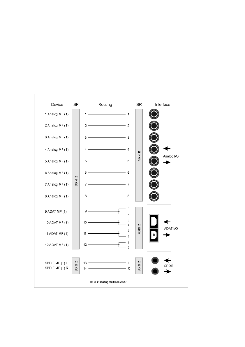
Multiset running under ASIO with ADAT optical at 96 kHz)
This diagram shows the signal paths in ASIO double speed mode (88.2 / 96
kHz). The devices available under ASIO have been implemented according
to the hardware. Signal routing is identical for record and playback.
Device: The device name in the audio application, SR: Sample Rate, Device name code: Channel in ASIO host, ADAT interface, Multiset, card
number
NUENDO AUDIOLINK 96
English – 64
Page 65

Digiset running under MME at 96 kHz
This diagram shows the signal paths in MME double speed mode (88.2
/ 96 kHz). The devices available via wave driver have been designed to
avoid conflicts in normal operation, which is why channels 5, 6, 7 and 8
of each ADAT device have been omitted. Signal routing is identical for
record and playback.
Device: The device name in the audio application, SR: Sample Rate
ENGLISH
NUENDO AUDIOLINK 96
English – 65
Page 66
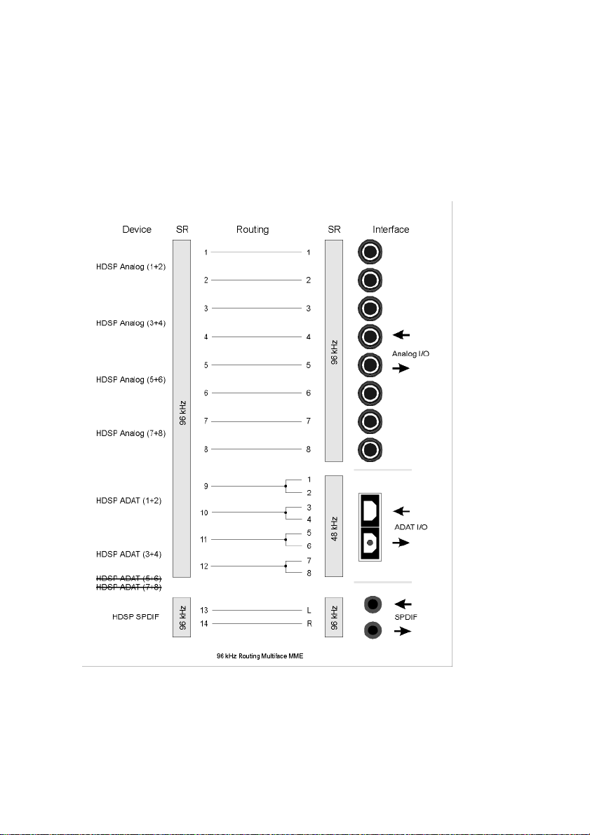
Multiset running under MME at 96 kHz
This diagram shows the signal paths in MME double speed mode (88.2
/ 96 kHz). The devices available via wave driver have been designed to
avoid conflicts in normal operation, which is why channels 5, 6, 7 and 8
of each ADAT device have been omitted. Signal routing is identical for
record and playback.
NUENDO AUDIOLINK 96
English – 66
Page 67

21.3 Block diagram TotalMix
This diagram shows the signal flow inside the TotalMix mixer of the
Digiset or Multiset. It shall clarify the following function:
• The input signal of the hardware (Digiset: ADAT/S/P-DIF In, Multiset: Analog/
ADAT/S/P-DIF) is always directly fed through to the recording software. At the
same time it can be routed to all 28 (Digiset) or 20 (Multiset) hardware outputs
(Digiset: ADAT/ S/P-DIF/ Analog, Multiset: Analog/ADAT/ S/P-DIF/Monitor),
even to all of them simultaneously.
ENGLISH
NUENDO AUDIOLINK 96
English – 67
Page 68

CE
This device has been tested and found to comply with the EN55022
class B and EN50082-1 norms for digital devices, according to the European Council directive on counterpart laws in the member states relating to electromagnetic compatibility (EMVG).
FCC
This device has been tested and found to comply with the requirements listed in FCC Regulations, part 15 for Class ‘B’ digital devices.
Compliance with these requirements provides a reasonable level of assurance that your use of this product in a residential environment will
not result in harmful interference with other electronic devices.
This equipment generates radio frequencies and, if not installed and
used according to the instructions in the User’s Guide may cause interference harmful to the operation of other electronic devices.
Compliance with FCC regulations does not guarantee that interference
will not occur in all installations. If this product is found to be the source
of interference, which can be determined by turning the unit off and on
again, please try to eliminate the problem by using one of the following measures:
• Relocate either this product or the device that is being affected by the interference
• Use power outlets on different branch circuits, or install AC line filters
• Contact your local retailer or any qualified radio and television engineer
When connecting external devices to this product, compliance to limits
for a Class ‘B’ device requires the use of shielded cables.
FCC compliance statement: Tested to comply with FCC standards for
home or office use.
NUENDO AUDIOLINK 96
English – 68
Page 69

Nuendo Audiolink 96
Audiolink 96 PCI (PCI-Interface-Karte)
Audiolink 96 Mobile (CardBus-Interface-Karte)
Nuendo Audiolink Digiset (In/Out-Box)
Nuendo Audiolink Multiset (In/Out-Box)
Handbuch
DEUTSCH DEUTSCH
NUENDO AUDIOLINK 96
Deutsch – 69
Page 70

1. Einleitung
❐
In diesem Handbuch wird die Verwendung von Nuendo Audiolink 96 im
Zusammenhang mit unterschiedlichen Computer-Betriebssystemen beschrieben. Wenn sich im Folgenden ein Textabschnitt auf nur eines der
kompatiblen Betriebssysteme bezieht, so wird dies durch einen entsprechenden Hinweis deutlich gemacht.
Vielen Dank für Ihr Vertrauen in Nuendo Audiolink 96. Dieses einmalige
Audiosystem ermöglicht das Überspielen digitaler Audiodaten von
praktisch allen Geräten mit digitalem Audioanschluss, sei es S/P-DIF,
AES/EBU oder ADAT optical, direkt in Ihren Computer.
Zahlreiche einzigartige Merkmale und ein durchdachter Settings-Dialog
stellen Nuendo Audiolink 96 an die Spitze aller Digital-Audio Interfacesysteme.
Im Lieferumfang befinden sich Treiber für Windows und MacOS.
Dank modernster Plug & Play-Technologie gestaltet sich die Installation
unter Windows auch für den unerfahrenen Anwender sehr einfach.
Unsere Hi-Performance-Philosophie garantiert volle Systemleistung,
indem alle Funktionen nicht vom Treiber (der CPU), sondern von der
Karten-Hardware ausgeführt werden.
NUENDO AUDIOLINK 96
Deutsch – 70
Page 71

2. Lieferumfang
Bitte überzeugen Sie sich vom vollständigen Lieferumfang des Nuendo
Audiolink 96-Systems.
Audiolink 96 PCI Interface-Karte
• Audiolink 96 PCI-Karte
• Treiber-CD
• Verbindungskabel IEEE1394, 4,5 m
• Internes Kabel (3-polig)
Audiolink 96 Mobile CardBus Interface-Karte
• PCMCIA Typ II CardBus-Karte
• Treiber-CD
• Verbindungskabel CardBus auf IEEE1394, 4,5 m
• 12 V-Autokabel
• Akkukabel
• Netzteil 12 V / 1,25 A mit Netzkabel
Digiset- bzw. Multiset-In/Out-Box
DEUTSCH DEUTSCH
• Digiset- oder Multiset-I/O-Box
• 3 optische Kabel (TOSLINK)
3. Systemvoraussetzungen
• Windows 98, Windows 2000, Windows XP oder MacOS (ab Version 9.1,
G3 300 MHz empfohlen)
• PCI-Interface: Ein freier PCI Busmaster-Steckplatz der PCI Rev. 2.1
• CardBus-Interface: Ein freier PCMCIA-Slot TypII, CardBus-fähig
NUENDO AUDIOLINK 96
Deutsch – 71
Page 72

4. Kurzbeschreibung und Eigenschaften
• 0% CPU-Belastung selbst bei Nutzung aller 36 (Multiset) bzw. 52 (Digiset)
ASIO-Kanäle
• Alle Einstellungen in Echtzeit änderbar
• Enhanced Mixed Mode: Analog, ADAT I/O plus S/P-DIF I/O simultan nutzbar (Mul-
tiset) bzw. ADAT In plus S/P-DIF In plus alle Ausgänge simultan nutzbar ( Digiset)
• 8 Puffergrößen/Latenzzeiten wählbar: 1,5 / 3 / 6 / 12 / 23 / 46 / 93 / 186 ms
• 4 (Multiset) bzw. 12 (Digiset) Kanäle 96 kHz/24 Bit Record/Playback über ADAT
optical dank Sample Split
• Clock-Modi Slave und Master
• Automatische und intelligente Master/Slave-Clocksteuerung
• Unübertroffene Bitclock PLL (Audio-Synchronisation) im ADAT-Betrieb
• Wordclock Ein- und Ausgang
• ADAT Sync In (9-pol Sub-D) für samplegenaue Transfers
• Zero Latency Monitoring: Hardware Bypass pro Spur, gesteuert von Punch-In/Out
• Enhanced-ZLM für Latenz-freie Submixe und perfektes ASIO Direct Monitoring
• SyncAlign garantiert samplegenaue und niemals wechselnde Kanalzuordnungen
• SyncCheck prüft die Synchronität der Eingangssignale
• 1 x MIDI I/O für16 Kanäle Hi-Speed MIDI (Multiset) bzw. 2 x MIDI I/O für 32 Kanäle
Hi-Speed MIDI (Digiset)
• 1 x Analog Line/Headphone Out, separater Ausgang für unabhängigen Submix
• DIGICheck DSP: Levelmeter in Hardware mit Peak- und RMS-Berechnung
• TotalMix: Mischer mit 40 Bit interner Auflösung, 720 Kanälen (Multiset) bzw. 1456
Kanälen (Digiset)
5. Technische Merkmale
5.1 Digitaler Teil – Multiset & Digiset
Multiset
• Super Low Jitter Design: < 3 ns Wordclock PLL, < 2 ns ADAT PLL, < 1 ns intern
• Interne Samplefrequenz: 32 / 44,1 / 48 / 88,2 / 96 kHz
• Unterstützte Samplefrequenz per Wordclock In: 27 kHz - 103 kHz
• Interne Auflösung: 24 Bit
• Eingangs-PLL arbeitet selbst mit mehr als 40 ns Jitter ohne Aussetzer
• Bitclock PLL für störungsfreies Vari-Speed im ADAT Betrieb
• Hochempfindliche Eingangsstufe (< 0,2 Vss Eingangspegel)
NUENDO AUDIOLINK 96
Deutsch – 72
Page 73

• Ausgangsspannung Cinch Consumer 0,8 V, Professional 2,3 V
• Digitale Ein- und Ausgänge vollständig galvanisch entkoppelt
• Anschlüsse: optisch (TOSLINK), Cinch, BNC
• Clocks: ADAT Sync In, Wordclock I/O
• Formate: S/P-DIF (Consumer und Professional), ADAT optical
Digiset
• Super Low Jitter Design: < 3 ns im PLL Betrieb (44,1 kHz, optical In, S/P-DIF)
• Super Low Jitter Design: < 2 ns im PLL Betrieb (44,1 kHz, optical In, ADAT)
• Eingangs-PLL arbeitet selbst mit mehr als 40 ns Jitter ohne Aussetzer
• Bitclock PLL für störungsfreies Vari-Speed im ADAT Betrieb
• Hochempfindliche Eingangsstufe (< 0,2 Vss Eingangspegel)
• Ausgangsspannung Cinch Consumer 0,8 V, Professional 2,3 V
• Unterstützte Samplefrequenz: 32 / 44,1 / 48 / 88,2 / 96 kHz und variabel
• Digitale Ein- und Ausgänge vollständig galvanisch entkoppelt
• Anschlüsse: optisch (TOSLINK), Cinch, BNC
• Clocks: ADAT Sync In, Wordclock I/O
• Formate: S/P-DIF (Consumer und Professional), ADAT optical
5.2 Analoger Teil – Multiset
DEUTSCH DEUTSCH
Stereo-Monitorausgang
• Ausgangspegel +8 dBu @ 0 dBFS
• Dynamik Ausgang: 108 dB (RMS unbewertet, unmuted), 112 dBA
• THD+N Ausgang: -100 dB / 0,001 %
• Frequenzgang DA, -0,1 dB: 20 Hz - 20,8 kHz (sf 44,1 kHz)
• Frequenzgang DA, -0,5 dB: 10 Hz - 44 kHz (sf 96 kHz)
• Samplefrequenz Wiedergabe: 32 / 44,1 / 48 / 64 / 88,2 / 96 kHz und variabel
(Wordclock)
• Ausgangsimpedanz: 75 Ohm
• Kanaltrennung: > 110 dB
AD
• Auflösung AD: 24 Bit
• Rauschabstand (SNR): 101 dB RMS unbewertet, 106 dBA
• THD: < -107 dB, < 0,00045 %
• THD+N: < -96 dB, < 0,0016 %
•Übersprechdämpfung: > 120 dB
NUENDO AUDIOLINK 96
Deutsch – 73
Page 74

• Analoger Headroom vor AD-Wandlung: 13 dB
• Frequenzgang AD @ 44,1 kHz, -0,5 dB: 5 Hz - 20,7 kHz
• Frequenzgang AD @ 96 kHz, -0,5 dB: 5 Hz - 32 kHz
• Eingang Line: 6,3 mm Stereoklinke, servosymmetrisch
• Eingangsimpedanz Line: > 5 kOhm
• Eingangsempfindlichkeit per Jumper: Lo Gain, +4 dBu, -10 dBV
• Eingangspegel für 0 dBFS @ Lo Gain: +19 dBu
• Eingangspegel für 0 dBFS @ +4 dBu: +13 dBu
• Eingangspegel für 0 dBFS @ -10 dBV: +2 dBV
DA
• Auflösung DA: 24 Bit
• Rauschabstand (DR): 108 dB RMS unbewertet, 111 dBA (ohne Mute)
• THD: < - 98 dB, < 0,0013 %
• THD+N: < -91 dB, < 0,002 %
•Übersprechdämpfung: > 100 dB
• Maximaler Ausgangspegel DA: +19 dBu
• Frequenzgang DA @ 44,1 kHz, -0,5 dB: 5 Hz - 20,9 kHz
• Frequenzgang DA @ 96 kHz, -0,5 dB: 5 Hz - 35 kHz
• Ausgang Line: 6,3 mm Stereoklinke, servosymmetrisch
• Ausgangsimpedanz Line: 47 Ohm
• Ausgangspegel per Jumper: Hi Gain, +4 dBu, -10 dBV
• Ausgangspegel bei 0 dBFS @ Hi Gain: +19 dBu
• Ausgangspegel bei 0 dBFS @ +4 dBu: +13 dBu
• Ausgangspegel bei 0 dBFS @ -10 dBV: +2 dBV
5.3 Analoger Teil – Digiset
• Ausgangspegel +10 dBu @ 0 dBFS
• Dynamik Ausgang: 108 dB (RMS unbewertet, unmuted), 112 dBA
• THD+N Ausgang: -100 dB / 0,001 %
• Frequenzgang DA, -0,1 dB: 20 Hz - 20,8 kHz (sf 44,1 kHz)
• Frequenzgang DA, -0,5 dB: 10 Hz - 44 kHz (sf 96 kHz)
• Samplefrequenz Wiedergabe: 32 / 44,1 / 48 / 64 / 88,2 / 96 kHz und variabel
(Wordclock)
• Ausgangsimpedanz: 75 Ohm
• Kanaltrennung: > 110 dB
NUENDO AUDIOLINK 96
Deutsch – 74
Page 75

5.4 Transfer-Modi: Auflösung / Bits pro Sample
Windows
ASIO:
24 / 32 Bit 4 Byte Stereo 8 Bytes
Dieses Format ist kompatibel mit 16 und 20 Bit. Auflösungen unter
24 Bit werden von der Anwendungssoftware bestimmt.
MME:
16 Bit 2 Byte (Stereo 4 Bytes)
20 Bit 3 Byte MSB (Stereo 6 Bytes)
20 Bit 4 Byte MSB (Stereo 8 Bytes)
24 Bit 3 Byte (Stereo 6 Bytes)
24 Bit 4 Byte MSB (Stereo 8 Bytes)
32 Bit 4 Byte (Stereo 8 Bytes)
DEUTSCH DEUTSCH
Die Karte arbeitet nur im Multi Device Modus, Channel Interleave wird
nicht unterstützt. Da die zusätzlichen Channel Status Bits nicht übertra-
gen werden, ist TMS (Track Marker Support) nicht möglich. Außerdem
arbeitet die Funktion Channel Status Display in DIGICheck nicht.
Macintosh
32 Bit 4 Bytes Stereo 8 Bytes
Dieses Format ist kompatibel mit 16 und 20 Bit. Auflösungen unter
24 Bit werden von der ASIO-Applikation bereitgestellt. Die Karte arbeitet intern immer mit 32 Bit, der Audio-Datentransfer ist jedoch auf 24 Bit
beschränkt.
NUENDO AUDIOLINK 96
Deutsch – 75
Page 76

6. Installation der Hardware
6.1 Audiolink 96 PCI-Interface-Karte
❐
Vor dem Einbau der PCI-Karte ist der Computer auszuschalten und durch
Abziehen des Netzkabels vom Stromnetz zu trennen. Das Ein- und Ausstecken der Karte im laufenden Betrieb führt zu einer irreparablen
Beschädigung von Mainboard und Karte.
1. Strom- und andere Anschlusskabel vom Rechner abziehen.
2. PC-Gehäuse öffnen. Genauere Hinweise enthalten die Unterlagen zu Ihrem Rechner.
3. Vor dem Auspacken der Karte aus der Schutzhülle: Elektrostatische Aufladungen durch Berühren des PC-Metallchassis ableiten.
4. Karte in einen freien PCI-Steckplatz drücken und festschrauben.
5. PC-Gehäuse wieder schließen und festschrauben.
6. Strom- und Anschlusskabel wieder befestigen.
7. Verbinden Sie PCI-Interface und Digiset bzw. Multiset mit dem mitgelieferten Kabel (IEEE1394). Hierbei handelt es sich um ein handelsübliches
Firewire-Kabel 6-polig.
6.2 Audiolink 96 Mobile-Karte
Vor dem Einstecken der CardBus-Karte ist das gesamte Audiolink 96System betriebsbereit zu machen!
1. Verbinden Sie die CardBus-Karte mit dem Digiset bzw. Multiset über das
mitgelieferte Spezialkabel.
2. CardBus-Karte mit dem Nuendo-Logo nach oben in den PCMCIA-Slot einstecken.
3. Den Niederspannungsstecker des mitgelieferten Netzteils in die Buchse
AUX stecken.
NUENDO AUDIOLINK 96
Deutsch – 76
Page 77

4. Netzkabel an Netzteil anstecken und in eine Netzsteckdose stecken. Die
grüne LED des Netzteiles und die rote LED des Digiset bzw. Multiset müssen nun leuchten.
5. Notebook einschalten und Betriebssystem hochfahren.
❐
Der kleine 15-polige Stecker in der CardBus-Karte ist kodiert. Es lässt sich
nur das mitgelieferte Spezialkabel einstecken, und nur mit der metallenen
Seite nach oben. Jede Gewaltanwendung bein Ein- und Ausstecken kann
zu einer Beschädigung der CardBus-Karte führen.
7. Installation der Treiber
7.1 Windows 98
Nach der Installation des Interfaces, Verkabelung mit dem Digiset bzw.
Multiset (siehe Seite 76) und Einschalten des Rechners findet Windows
eine neue Hardwarekomponente und startet den Assistenten zur Geräteinstallation. Legen Sie die Treiber-CD in das CD-ROM-Laufwerk und
folgen Sie den Anweisungen des Assistenten am Bildschirm.
DEUTSCH DEUTSCH
Windows installiert nun die Treiber des Nuendo Audiolink 96-Systems und
meldet es als Audiogerät im System an. Danach ist es direkt betriebsbereit.
❐
Leider muss manchmal der Pfad zum CD-ROM–Laufwerk (dessen Laufwerksbuchstabe) während des Kopiervorgangs erneut eingegeben werden.
Die Konfiguration des Audiolink 96-Systems erfolgt über einen eigenen
Settings-Dialog (siehe Seite 92).
7.2 Windows 2000
Nach der Installation des Interfaces, Verkabelung mit dem Digiset oder
Multiset (siehe Seite 80) und Einschalten des Rechners findet Windows
eine neue Hardwarekomponente und startet den Assistenten zur Geräteinstallation. Legen Sie die Treiber-CD in das CD-ROM-Laufwerk,
und folgen Sie den Anweisungen des Assistenten am Bildschirm. Verweisen Sie während der Installation auf das Verzeichnis \win2000 der
Treiber-CD.
NUENDO AUDIOLINK 96
Deutsch – 77
Page 78

Windows installiert nun die Treiber des Nuendo Audiolink 96-Systems
und meldet es als Audiogerät im System an. Nach einem Neustart ist es
betriebsbereit.
❐
Leider muss manchmal der Pfad zum CD-ROM-Laufwerk (dessen Laufwerksbuchstabe) während des Kopiervorgangs erneut eingegeben werden.
Die Konfiguration des Audiolink 96-Systems erfolgt über einen eigenen
Settings-Dialog (siehe Seite 92).
Falls Warnmeldungen über 'Digitale Signatur nicht gefunden' erscheinen: einfach ignorieren und Installation fortsetzen.
7.3 Macintosh
Nach dem Einbau der Hardware (siehe Seite 76) und Boot des Rechners
installieren Sie die Treiber von der Treiber-CD. Die Treiberdateien befinden sich im Ordner 'Nuendo Audiolink 96'.
Falls Sie eine neuere Version von der Website heruntergeladen haben,
doppelklicken Sie auf das 'madsp_x.sit'-Archiv, um es in separate Dateien zu entpacken (dies geschieht mittels Aladdin Stuffit Expander).
❐
Ist bereits eine ältere Treiberversion installiert, entfernen Sie zunächst die
alte Treibersoftware. Öffnen Sie den Ordner 'Systemerweiterungen' im
'System-Ordner' und ziehen die Datei 'Nuendo Audiolink 96 Driver' in den
Papierkorb. Gleiches bitte für die Datei 'Nuendo Audiolink 96 Settings',
welche sich in dem von Ihnen gewählten Ordner befindet. Löschen Sie
'Nuendo Audiolink 96 ASIO' in jedem 'ASIO Drivers' Ordner.
Ziehen Sie nach der Dekompression die Datei Nuendo Audiolink 96
Driver auf den System-Ordner. Die Installation erfolgt automatisch in
den Ordner 'Systemerweiterungen'. Bestätigen Sie die Rückfrage des
Systems zur Installation. Danach sollte sich die Treiberdatei im Ordner
'Systemerweiterungen' befinden.
Kopieren Sie die Dateien Nuendo Audiolink 96 Settings und Nuendo
Audiolink 96 ASIO in jeden 'ASIO Drivers' Ordner Ihres Rechners. Da jedes ASIO-fähige Programm einen eigenen solchen Ordner besitzt, müssen die Dateien mehrmals von Hand kopiert werden.
NUENDO AUDIOLINK 96
Deutsch – 78
Page 79

Die Konfiguration der Nuendo Audiolink 96 erfolgt durch Aufruf des Settings-Dialoges aus dem jeweiligen ASIO-Programm heraus (z.B. Audio/
System/ASIO-Systemsteuerung). Um den Settings-Dialog ( jederzeit aufrufen zu können, empfiehlt sich die Erzeugung eines Alias beispielsweise
auf dem Desktop. Ein Alias entsteht, wenn Sie 'Nuendo Audiolink 96 Settings' mit dem Mauszeiger anfassen, die Tastenkombination Befehl-Wahl
(Apfel-Alt) gedrückt halten, und 'Nuendo Audiolink 96 Settings' an den
gewünschten Ort ziehen. Siehe auch Seite 89.
Außer den drei Treiberdateien Nuendo Audiolink 96 Driver, Nuendo
Audiolink 96 Settings und Nuendo Audiolink 96 ASIO befinden sich im Archiv weitere Dateien:
digibox.bin Firmware der Digiset I/O Box
default.mix Default-Einstellung für TotalMix
default.vol Default-Einstellung für Digiset, solange
TotalMix noch nicht gestartet wurde
preset1.mix bis
preset8.mix
❐
Diese Dateien müssen alle in den System-Ordner 'Preferences' kopiert werden!
Presets des Audiolink 96 Mischers
DEUTSCH DEUTSCH
Die Datei 'digibox.bin' enthält die Firmware des Digiset, die automatisch beim Booten des Rechners in das Digiset geladen wird.
Die Dateien 'default.mix' und 'default.vol' enthalten den letztmaligen
Mischerzustand.
Die Dateien 'preset1.mix' bis 'preset8.mix' enthalten den kompletten,
per Preset-Button abrufbaren Mischerzustand.
Die Datei 'Nuendo Audiolink 96 TotalMix' kann an jeden gewünschten
Ort kopiert werden. Beim Aufruf erscheint der Audiolink 96-Mischer und
erlaubt eine Konfiguration des digitalen Echtzeit-Mischers des Digiset.
❐
TotalMix erfordert die Carbon Library 1.1, die seit MacOS 9.1 im System
enthalten ist. Nach der Installation der Carbon Library 1.1 ist TotalMix
auch unter älteren Systemen (ab 8.6) lauffähig.
Zum Abschluss der Installation ist der Rechner neu zu booten.
NUENDO AUDIOLINK 96
Deutsch – 79
Page 80

8. Inbetriebnahme und Bedienung
8.1 Anschlüsse
Digiset
Auf der Frontseite der I/O-Box Multiset befinden sich der MIDI-Ein- und
Ausgang, der analoge Stereo-Ausgang des Digitalmischers, sowie
mehrere Status LEDs.
Auf der Frontseite der I/O-Box Digiset befinden sich der zweite MIDI-Einund Ausgang, der analoge Stereo-Ausgang des Digitalmischers, sowie
mehrere Status LEDs:
MIDI State signalisiert für jeden MIDI-Port getrennt, ob Daten gesen-
det oder empfangen werden.
Input State signalisiert für jeden Eingang getrennt, ob ein gültiges Ein-
gangssignal anliegt. SyncCheck zeigt zusätzlich per blinkender LED,
welches der Eingangssignale zwar gelockt, nicht aber synchron zu den
anderen ist. Siehe auch Seite 96.
Die rote LED HOST leuchtet nach Anstecken des Netzteiles bzw. Einschalten des Rechners rot auf und signalisiert damit das Vorhandensein
der Betriebsspannung. Gleichzeitig dient sie als Error-LED (Fehler),
wenn die I/O-Box noch nicht initialisiert wurde oder die Verbindung
zum Interface unterbrochen wurde (Error, Kabel nicht gesteckt etc.).
Phones ist ein niederohmiger Line-Ausgang höchster Qualität, der in der
Lage ist, genug Lautstärke unverzerrt auch in Kopfhörern zu erzeugen.
Auf der Rückseite des Digiset befinden sich der erste MIDI-Ein- und
Ausgang, der Netzteilanschluss AUX (nur bei Betrieb mit CardBus-Karte
notwendig), sowie sämtliche digitalen Ein- und Ausgänge:
ADAT I/O (TOSLINK), 1 bis 3. ADAT1 kann nach Umschaltung im SettingsDialog ( auch als optischer S/P-DIF Ein- und Ausgang genutzt werden.
S/P-DIF I/O Koaxial (Cinch)
Wordclock I/O (BNC)
ADAT Sync In (Sub-D 9-polig)
NUENDO AUDIOLINK 96
Deutsch – 80
Page 81

Die Konfiguration des S/P-DIF-Einganges erfolgt über den Nuendo
Audiolink 96 Settings-Dialog. Das Audiolink 96-System akzeptiert alle
üblichen Digitalquellen, sowohl S/P-DIF als auch AES/EBU. Kennung
und Kopierschutz werden ignoriert.
Optischer und koaxialer Ausgang arbeiten im S/P-DIF-Betrieb parallel,
geben also ein identisches Signal aus. So lassen sich auch zwei S/P-DIFGeräte gleichzeitig anschließen und die Audiolink 96 als Splitter benutzen (Verteilung 1 auf 2).
Das Einspeisen von Signalen im AES/
EBU Format erfordert einen Kabeladapter. Dazu werden die Pins 2 und 3
einer XLR-Kupplung einzeln mit den
beiden Anschlüssen eines Cinch-Steckers verbunden. Die abschirmende Masse des Kabels ist nur an Pin 1
der XLR-Kupplung anzuschließen.
Die Trafosymmetrierung des koaxialen Ein- und Ausganges bietet neben dem problemlosen Anschluss eines AES/EBU-Gerätes eine sichere
Vermeidung von Brummschleifen.
Multiset
DEUTSCH DEUTSCH
Auf der Frontseite der I/O-Box Multiset befinden sich der MIDI-Ein- und
Ausgang, der analoge Stereo-Ausgang des Digitalmischers, sowie
mehrere Status LEDs:
MIDI State signalisiert, ob MIDI-Daten gesendet oder empfangen werden.
Input State signalisiert getrennt für jeden digitalen Eingang, ob ein
gültiges Eingangssignal anliegt. SyncCheck zeigt zusätzlich per blinkender LED, welches der Eingangssignale zwar gelockt, nicht aber synchron
zu den anderen ist. Siehe auch »9.2 Clock-Modi – Synchronisation« auf
Seite 96.
Die rote LED HOST leuchtet nach Anstecken des Netzteiles bzw. Einschalten des Rechners rot auf und signalisiert damit zunächst eine anliegende Betriebsspannung. Gleichzeitig dient sie als Error-LED (Fehler),
wenn die I/O-Box noch nicht initialisiert wurde, oder die Verbindung
zum Interface unterbrochen wurde (Error, Kabel nicht gesteckt etc.).
NUENDO AUDIOLINK 96
Deutsch – 81
Page 82

Phones ist ein niederohmiger Line-Ausgang höchster Qualität, der in der
Lage ist, genug Lautstärke unverzerrt auch in Kopfhörern zu erzeugen.
Auf der Rückseite des Multiset befinden sich die 8 analogen Ein- und
Ausgänge, der Netzteilanschluss AUX (nur bei Betrieb mit CardBus-Karte
notwendig), sowie sämtliche digitalen Ein- und Ausgänge:
ADAT I/O (TOSLINK). Kann nach Umschaltung im Settings-Dialog auch
als optischer S/P-DIF Ein- und Ausgang genutzt werden.
S/P-DIF I/O Koaxial (Cinch)
Wordclock I/O (BNC)
ADAT Sync In (Sub-D 9-polig)
Die Konfiguration des S/P-DIF-Einganges erfolgt über den Settings-Dialog , aufzurufen per Mausklick auf das Nuendo-Symbol im Systray der
Taskleiste. Das Audiolink 96-System akzeptiert alle üblichen Digitalquellen, sowohl S/P-DIF als auch AES/EBU. Kennung und Kopierschutz
werden ignoriert.
Optischer und koaxialer Ausgang arbeiten im S/P-DIF-Betrieb parallel,
geben also ein identisches Signal aus. So lassen sich auch zwei S/P-DIFGeräte gleichzeitig anschließen, und die Audiolink 96 als Splitter benutzen (Verteilung 1 auf 2).
Das Einspeisen von Signalen im Format AES/EBU erfordert einen Kabeladapter. Dazu werden die Pins 2 und 3
einer XLR-Kupplung einzeln mit den
beiden Anschlüssen eines Cinch-Steckers verbunden. Die abschirmende Masse des Kabels ist nur an Pin 1
der XLR-Kupplung anzuschließen.
Die Trafosymmetrierung des koaxialen Ein- und Ausganges bietet neben dem problemlosen Anschluss eines AES/EBU-Gerätes eine sichere
Vermeidung von Brummschleifen.
NUENDO AUDIOLINK 96
Deutsch – 82
Page 83
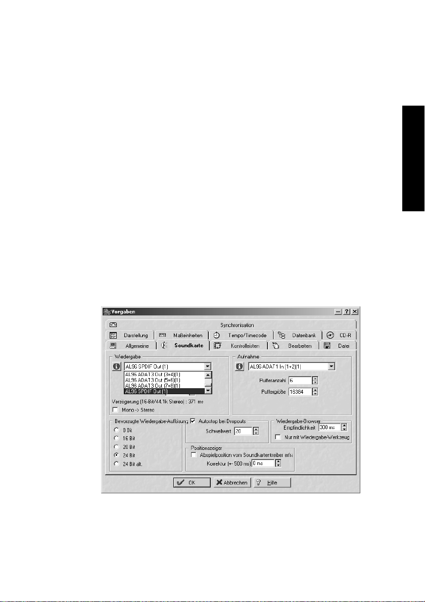
8.2 Wiedergabe Windows MME
Das Audiolink 96-System sendet digitale Audiodaten automatisch in
den Parametern der Wavedatei, wenn das auszugebende Format unterstützt wird. Ansonsten erscheint eine Fehlermeldung.
Zuerst ist Audiolink 96 als ausgebendes Gerät in der jeweiligen Software einzustellen. Übliche Bezeichnungen sind Playback Device, Device,
Audiogerät etc, meist unter Optionen, Vorgaben oder Preferences zu finden. Als Wiedergabeauflösung empfehlen wir 24 Bit, da nur in dieser
Einstellung die volle Leistung des Audiolink 96-Systems zur Verfügung
steht.
Wir empfehlen dringend, alle Systemsounds abzustellen (über >Systemsteuerung/Akustische Signale<), und das Audiolink 96 keinesfalls
als Bevorzugtes Wiedergabegerät einzustellen, da es sonst zu Synchronisationsverlust und Störgeräuschen kommen kann. Wenn Sie ohne Systemsounds nicht leben können, empfehlen wir den zusätzlichen
Erwerb eines günstigen Blaster-Clones. Dieser sollte dann als Bevorzug-
tes Wiedergabegerät in >Systemsteuerung / Multimedia / Audio< konfi-
guriert werden.
DEUTSCH DEUTSCH
NUENDO AUDIOLINK 96
Deutsch – 83
Page 84

Das Beispiel auf der Vorseite zeigt einen typischen Konfigurationsdialog eines (2-spurigen) Wave-Programmes. Eine Wiedergabe ist nach
Auswahl des entsprechende Devices sowohl auf dem S/P-DIF- als auch
den ADAT Ports möglich.
Mehr oder größere Buffer ergeben eine höhere Störsicherheit, aber
auch eine größere Verzögerung bis zur Ausgabe der Daten. Im Falle
von synchroner Audioausgabe zu MIDI oder ähnlichem, aktivieren Sie
auf jeden Fall die Option 'Abspielposition vom Soundkartentreiber erfragen'. Da die Nuendo Audiolink 96 die aktuelle Abspielposition korrekt zurückmeldet (übrigens auch bei Aufnahme, was im Chase Lock
Sync Betrieb sogar unverzichtbar ist), gibt es auch bei größeren Buffereinstellungen keine Timing-Probleme mit gemischten Audio- und MIDI
Anwendungen.
Mit dem Audiolink 96-System ist es möglich über die ADAT optical
Schnittstelle(n) bis zu 96 kHz Samplefrequenz zu nutzen (also auf einem handelsüblichen ADAT Rekorder aufzuzeichnen). Dazu werden
die Daten eines Kanales im Sample-Split-Verfahren auf zwei Kanäle verteilt. Demzufolge stehen statt 8 (Multiset) bzw. 24 (Digiset) nur noch 4
(Multiset) bzw. 12 (Digiset) ADAT-Spuren zur Verfügung. Unter Windows MME ist die Spurverteilung auf den ADAT Devices im Double
Speed Modus folgendermaßen geregelt:
• Es sind nur noch die Stereopaare (1+2) und (3+4) eines ADAT Ports ansprechbar.
• Der Kanal 1 wird auf den Kanälen 1 und 2 ausgegeben, der Kanal 2 auf 3 und 4 usw.
Auf Seite 133 finden Sie eine Darstellung, welche den Sachverhalt noch
einmal erläutert. Für die Aufnahme gilt die gleiche Verteilung.
8.3 Aufnahme Windows MME
Im Gegensatz zu analogen Soundkarten, welche auch ohne Eingangssignal eine leere (nur aus Rauschen bestehende) Wavedatei erzeugen,
müssen digitale Interface-Systeme zum Start einer Aufnahme immer
ein gültiges Eingangssignal erhalten.
Wegen dieser Besonderheit wurde das Nuendo Audiolink 96-System
mit drei einzigartigen Merkmalen versehen: einer umfassenden Statusanzeige in der Settingsbox für Ein- und Ausgangsignal, welche Samplefrequenz, Lock und Sync Status anzeigt, Status-Leuchtdioden für jeden
Eingang, sowie der Sicherheitsfunktion Check Input.
NUENDO AUDIOLINK 96
Deutsch – 84
Page 85
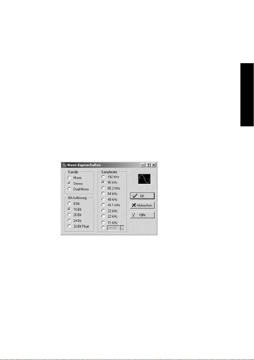
Wenn ein Signal mit 48 kHz anliegt, die Aufnahme-Software jedoch auf
44,1 kHz eingestellt ist, wird die Aufnahme verweigert (Check Input).
Dies verhindert fehlerhafte Aufnahmen, die sich weniger durch
schlechten Klang als durch eine falsche Wiedergabegeschwindigkeit
auszeichnen, was oft erst in einem späteren Stadium der Bearbeitung
bemerkt wird.
Die Anzeige der Samplefrequenz (siehe Kapitel »9. Konfiguration des
Digiset bzw. Multiset« auf Seite 89) in der Statusanzeige bietet einen
schnellen Überblick über die aktuelle Konfiguration von Karte und extern angeschlossenem Equipment. Liegt keine erkennbare Frequenz
an erscheint ‘No Lock’.
Damit wird eine Konfiguration der jeweiligen Software zur Durchführung
einer digitalen Aufnahme zum Kinderspiel. Nach der Wahl des richtigen
Eingangs zeigt Ihnen das Audiolink 96-System die aktuelle Samplefrequenz. Diese können Sie nun im Eigenschaftendialog des jeweiligen Aufnahme-Programmes einstellen.
Der nebenstehende Screenshot zeigt einen solchen Dialog, in dem grundlegende Parameter wie Samplefrequenz
und Bitauflösung einzustellen
sind.
DEUTSCH DEUTSCH
Bei der Wahl der Bitauflösung
sind prinzipiell beliebige Einstellungen möglich, solange
diese von der Hardware unter-
stützt werden. Auch wenn am
Eingang 24 Bit anliegen, kann man die Software mit nur 16 Bit aufnehmen lassen. Die unteren Bits (und damit alle Signale circa 95 dB unterhalb der Vollaussteuerung) gehen dann jedoch unwiderruflich verloren.
Umgekehrt bringt die Aufnahme in 24 Bit von einer 16-bittigen Quelle
keinerlei Gewinn, verschwendet jedoch unnötig Speicherplatz.
NUENDO AUDIOLINK 96
Deutsch – 85
Page 86

Oft ist es sinnvoll das Eingangssignal abzuhören oder weiterzuleiten.
Für solche Fälle enthält das Audiolink 96-System neben dem frei konfigurierbaren TotalMix (siehe »14. TotalMix: Routing und Monitoring«
auf Seite 111) einen nützlichen Automatik-Echtzeit-Monitorbetrieb,
der im Settings-Dialog aktivierbar ist (Monitoring). Ein 'Scharfschalten'
der Aufnahmesoftware per Pause oder Record führt dann zum Durchschleifen des Eingangssignales zum jeweils gleichen Ausgang.
Um bei einer Aufnahme einen gesteuerten Echtzeit-Monitoring-Betrieb
zu erlauben existieren derzeit zwei Lösungen. ZLM erlaubt das Monitoring im Punch-I/O-Betrieb, das System verhält sich damit wie eine Bandmaschine. Dieses Verfahren ist derzeit in allen Samplitude-Versionen
von SEK'D enthalten und wird innerhalb der Programme über die globale Spuroption 'Hardware Monitoring während Punch aktiv' aktiviert.
Die zweite Lösung bietet Steinbergs ASIO Protokoll mit unseren ASIO-
2.0-Treibern und jedem mit ASIO 2.0 kompatiblen Programm. Nach Aktivierung der Option 'ASIO Direct Monitoring' wird ab Punch-In das Eingangssignal in Echtzeit zum Ausgang durchgeschliffen. Im Gegensatz
zu ZLM ist dabei das Monitoring frei misch- und routbar, das Durchschleifen also nicht auf den gleichen Kanal beschränkt.
8.4 Aufnahme analog – Multiset
Aufnahmen über die analogen Eingänge gelingen nach Anwahl eines
entsprechenden Aufnahmedevices (Audiolink 96 Analog (x+x)). Das
Multiset besitzt – abgesehen vom per Jumper einstellbaren Arbeitspegel – keine Pegeleinstellmöglichkeit für die Eingangssignale. Digital
wäre dies sowieso Unsinn, aber auch analog kann darauf problemlos
verzichtet werden. Egal ob das Multiset an einem Mischpult oder einem mehrkanaligen Mikrofonvorverstärker betrieben wird, im Normalfall kann der Pegel an der Quelle perfekt an das Multiset angepasst
werden.
Die Eingangsempfindlichkeit der analogen Eingänge kann über interne
Jumper an die weltweit gängigsten Pegel angepasst werden, siehe »9.3
Ändern der Jumpereinstellung – Multiset« auf Seite 100.
NUENDO AUDIOLINK 96
Deutsch – 86
Page 87

8.5 Analoge Eingänge – Multiset
Das Multiset besitzt symmetrische Line-Eingänge in Form von 6,3 mm
Stereo-Klinkenbuchsen. Die elektronische Eingangsschaltung arbeitet
servosymmetrisch. Sie kann sowohl symmetrische (Stereo-Klinkenstecker) als auch unsymmetrische (Mono-Klinkenstecker) Eingangssignale
korrekt verarbeiten, bei unveränderter Pegelreferenz.
❐
Bei Verwendung von unsymmetrischen Verbindungen mit Stereo-Klinkensteckern sollte deren Anschluss 'Ring' mit Masse verbunden sein, da es
sonst zu Störgeräuschen durch den 'offenen' negativen Eingang der symmetrischen Eingangsstufe kommen kann.
Eines der Hauptprobleme eines AD-Wandlers ist die korrekte Anpassung
des Nennpegels, damit der Wandler stets im optimalen Arbeitsbereich
betrieben wird. Deshalb besitzt das Multiset interne Jumper, mit denen
sich alle 8 Kanäle getrennt an die drei gebräuchlichsten Arbeitspegel anpassen lassen.
Der 'genormte' Studiopegel führt nicht zur (oft erwünschten) Vollaussteuerung, sondern berücksichtigt einen zusätzlichen digitalen Headroom. Der Headroom ist leider in verschiedenen Normen verschieden
definiert, und daher unter den Geräteherstellern nicht einheitlich implementiert. Wir haben versucht, die Pegeldefinition des Multiset möglichst kompatibel umzusetzen.
DEUTSCH DEUTSCH
Referenz 0 dBFS @ Headroom
Lo Gain +19 dBu 15 dB
+4 dBu +13 dBu 9 dB
-10 dBV +2 dBV 12 dB
Das Gerät wird in der Stellung +4 dBu ausgeliefert. Der dabei vorhandene Headroom von 9 dB entspricht den aktuellen Empfehlungen der
EBU im Rundfunkbereich. Bei -10 dBV sind 12 bis 15 dB Headroom üblich, jedes Mischpult in -10 dBV Technik liefert und verkraftet relativ
hohe Pegel. Lo Gain eignet sich besonders für Anwender, welche gerne
symmetrisch und hochpegelig arbeiten, und entspricht einem Arbeitspegel von + 4 dBu mit 15 dB Headroom.
NUENDO AUDIOLINK 96
Deutsch – 87
Page 88

Informationen zur Änderung der Jumpereinstellung enthält der Abschnitt »9.3 Ändern der Jumpereinstellung – Multiset« auf Seite 100.
8.6 Analoge Ausgänge – Multiset
Die kurzschlussfesten und niederohmigen symmetrischen Line-Ausgänge sind in Form von 6,3 mm Stereo-Klinkenbuchsen realisiert. Die
elektronische Ausgangsschaltung arbeitet servosymmetrisch. Sie kann
sowohl symmetrisch (Stereo-Klinkenstecker) als auch unsymmetrisch
(Mono-Klinkenstecker) betrieben werden.
Um den analogen Ausgang optimal an nachfolgende Geräte anpassen
zu können besitzt das Multiset interne Jumper, mit denen der Ausgangspegel aller 8 Kanäle getrennt eingestellt werden kann.
Wie die analogen Eingangspegel sind auch die analogen Ausgangspegel des Multiset so ausgelegt, dass sie mit möglichst allen Geräten stör-
frei zusammenarbeiten. Der Headroom des Multiset beträgt daher je
nach Referenzpegel zwischen 9 und 15 dB:
Referenz 0 dBFS @ Headroom
Hi Gain +19 dBu 15 dB
+4 dBu +13 dBu 9 dB
-10 dBV +2 dBV 12 dB
Das Gerät wird in der Stellung +4 dBu ausgeliefert. Der dabei vorhandene Headroom von 9 dB entspricht den aktuellen Empfehlungen der
EBU im Rundfunkbereich. Bei -10 dBV sind 12 bis 15 dB Headroom üblich, jedes Mischpult in -10 dBV Technik liefert und verkraftet relativ
hohe Pegel. Hi Gain eignet sich besonders für Anwender, welche gerne
symmetrisch und hochpegelig arbeiten, und entspricht einem Arbeitspegel von + 4 dBu mit 15 dB Headroom.
Informationen zur Änderung der Jumpereinstellung finden Sie auf
Seite 100.
NUENDO AUDIOLINK 96
Deutsch – 88
Page 89
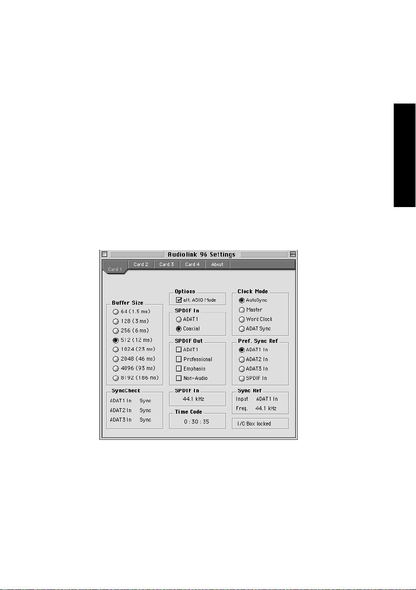
9. Konfiguration des Digiset bzw. Multiset
9.1 Allgemeines
Macintosh
Die Konfiguration des Audiolink 96-Systems Digiset erfolgt über einen
eigenen Settings-Dialog.
• Auf dem Macintosh lässt sich der Settings-Dialog durch Starten des Programms
Nuendo Audiolink 96 Settings aufrufen.
Die Hardware des Audiolink 96-Systems stellt eine Reihe hilfreicher,
durchdachter und praxisgerechter Funktionen und Optionen bereit,
mit denen der Betrieb gezielt den aktuellen Erfordernissen angepasst
werden kann. Über 'Settings' besteht Zugriff auf:
DEUTSCH DEUTSCH
• Die Umschaltung des Einganges
• Die Arbeitsweise des Ausganges
• Die Kennung auf dem Ausgang
• Das Synchronisationsverhalten
• Den Status von Ein- und Ausgang
• Die Anzeige des Timecodes
NUENDO AUDIOLINK 96
Deutsch – 89
Page 90

Alle Einstellungen im Settings-Dialog werden in Echtzeit übernommen,
sind also ohne Klick auf 'OK' oder das Schließen der Dialogbox aktiv.
Veränderungen an den Settings sollten möglichst nicht während laufender Wiedergabe oder Aufnahme erfolgen, da es sonst zu Störungen
kommen kann. Bitte beachten Sie, dass verschiedene Programme auch
im Modus 'Stop' das Aufnahme- und Wiedergabegerät geöffnet halten,
und deshalb die neuen Einstellungen eventuell nicht sofort wirksam
werden.
Die Statusanzeigen im unteren Teil des Settings-Dialoges geben genaue Auskunft über den Betriebszustand des Systems, sowie den aller
anliegenden Signale. SyncCheck zeigt für alle Eingänge getrennt an, ob
ein gültiges Signal anliegt, (No Lock, Lock), oder ob ein gültiges und
synchrones Signal anliegt (Sync). Die Anzeige der Sync Referenz gibt
an, zu welchem Signal die Synchronität besteht.
Im Feld 'Time Code' wird die Zeitinformation am 'ADAT Sync In' der
Karte ausgegeben, so dass die korrekte Zusammenarbeit beispielsweise mit einem ADAT-Recorder auf einen Blick ersichtlich ist.
Buffer Size
Die Einstellung der 'Buffer Size' (Puffergröße) bestimmt unter ASIO sowohl die Latenz zwischen eingehenden und ausgehenden Daten, als
auch die Betriebssicherheit des Systems (siehe Kapitel »13. Betrieb unter ASIO 2.0« auf Seite 107). Wir empfehlen, den höchsten Wert (8192
Samples) einzustellen, da die Karte selbst dann noch angenehm schnell
arbeitet. Unter Windows MME wird die Latenz innerhalb der jeweiligen
Anwendungssoftware eingestellt. Unter GSIF ist die Latenz fest vom
Programm vorgegeben.
NUENDO AUDIOLINK 96
Deutsch – 90
Page 91
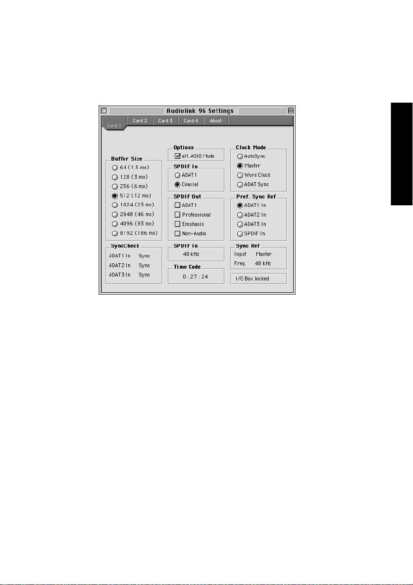
S/P-DIF In
Bestimmt den Eingang für das S/P-DIF-Signal. 'Coaxial' entspricht der
Cinchbuchse, 'ADAT1' dem optischen Eingang ADAT1.
DEUTSCH DEUTSCH
S/P-DIF Out
Das S/P-DIF-Ausgangssignal steht konstant an der Cinchbuchse bereit,
nach Anwahl von 'ADAT1' auch am optischen Ausgang ADAT1. Näheres zu Professional, Emphasis und Non-Audio finden Sie in Kapitel 12.
Clock Mode
Die Karte kann als Clock-Quelle das über Pref. Sync Ref gewählte Eingangssignal (AutoSync), ihre eigene Clock (Master), ein Wordclocksignal (Wordclock), oder den ADAT-Sync-Anschluss verwenden.
Pref. Sync Ref.
Dient zur Voreinstellung der bevorzugten Clock-Quelle. Steht die gewählte nicht zur Verfügung wechselt die Karte automatisch zur
nächsten verfügbaren Quelle. Die aktuell verwendete Clock-Quelle und
Samplefrequenz wird im Feld SyncRef angezeigt.
NUENDO AUDIOLINK 96
Deutsch – 91
Page 92

Options
'Alt. ASIO Mode' aktiviert ein anderes Verfahren der ASIO-Abwicklung.
Die Umschaltung erfolgt in Echtzeit und im laufenden Betrieb. Es lässt
sich daher sehr leicht feststellen, ob ein Programm im alternativen
ASIO-Modus eine höhere Performance bringt. Versuchen Sie es mit dieser Einstellung, wenn Sie Software anderer Hersteller verwenden.
I/O-Box Status:
In diesem Feld wird der aktuelle Status der I/O-Box angezeigt:
I/O Box error I/O-Box nicht angeschlossen oder ohne Strom.
I/O Box detected Das Interface hat eine I/O-Box erkannt und ver-
sucht sie zu initialisieren.
I/O Box locked Kommunikation zwischen Interface und I/O-Box
arbeitet korrekt.
Windows
Die Konfiguration des Audiolink 96-Systems Digiset bzw. Multiset erfolgt über einen eigenen Settings-Dialog. Das Fenster 'Settings' lässt
sich auf zwei Arten aufrufen:
• Per Mausklick auf das Nuendo-Symbol rechts unten in der Taskleiste
• Per Mausklick auf die Verknüpfung 'Audiolink 96_Set' auf dem Desktop
Der Mischer des Nuendo Audiolink 96-Systems (TotalMix) lässt sich auf
zwei Arten aufrufen:
• Per Mausklick auf das Mischersymbol rechts unten in der Taskleiste
• Per Mausklick auf die Verknüpfung 'Audiolink 96_Mix' auf dem Desktop
NUENDO AUDIOLINK 96
Deutsch – 92
Page 93

Die Hardware des Audiolink 96-Systems stellt eine Reihe hilfreicher,
durchdachter und praxisgerechter Funktionen und Optionen bereit,
mit denen der Betrieb gezielt den aktuellen Erfordernissen angepasst
werden kann. Über 'Settings' besteht Zugriff auf:
Digiset Settings Multiset Settings
• Die Umschaltung des Einganges
• Die Arbeitsweise des Ausganges
• Die Kennung auf dem Ausgang
• Das Synchronisationsverhalten
• Den Status von Ein- und Ausgang
• Die Anzeige des Timecodes
DEUTSCH DEUTSCH
Alle Einstellungen im Settings-Dialog werden in Echtzeit übernommen,
sind also ohne Klick auf 'OK' oder das Schließen der Dialogbox aktiv. Veränderungen an den Settings sollten möglichst nicht während laufender
Wiedergabe oder Aufnahme erfolgen, da es sonst zu Störungen kommen kann. Bitte beachten Sie, dass verschiedene Programme auch im
Modus 'Stop' das Aufnahme- und Wiedergabegerät geöffnet halten, und
deshalb die neuen Einstellungen eventuell nicht sofort wirksam werden.
Die Statusanzeigen im unteren Teil des Settings-Dialoges geben genaue Auskunft über den Betriebszustand des Systems, als auch den aller anliegenden Signale bzw. Digitalsignale. SyncCheck zeigt für alle
Eingänge (Digiset) bzw. die Eingänge ADAT, S/P-DIF und Wordclock
getrennt (Multiset) an, ob ein gültiges Signal anliegt, (No Lock, Lock),
oder ob ein gültiges und synchrones Signal anliegt (Sync). Die Anzeige
der Sync Referenz gibt an, zu welchem Signal die Synchronität besteht.
NUENDO AUDIOLINK 96
Deutsch – 93
Page 94

Im Feld 'Time Code' wird die Zeitinformation am 'ADAT Sync In' der
Karte ausgegeben, so dass die korrekte Zusammenarbeit beispielsweise mit einem ADAT-Recorder auf einen Blick ersichtlich ist.
Buffer Size
Die Einstellung der 'Buffer Size' (Puffergröße) bestimmt unter ASIO sowohl die Latenz zwischen eingehenden und ausgehenden Daten, als
auch die Betriebssicherheit des Systems (siehe Kapitel »13. Betrieb unter ASIO 2.0« auf Seite 107). Wir empfehlen, den höchsten Wert (8192
Samples) einzustellen, da die Karte selbst dann noch angenehm schnell
arbeitet. Unter Windows MME wird die Latenz innerhalb der jeweiligen
Anwendungssoftware eingestellt.
S/P-DIF In
Bestimmt den Eingang für das S/P-DIF-Signal. 'Coaxial' entspricht der
Cinchbuchse, 'ADAT1' dem optischen Eingang ADAT1 (Digiset) bzw.
'ADAT' dem optischen Eingang ADAT (Multiset).
S/P-DIF Out
Das S/P-DIF-Ausgangssignal steht konstant
an der Cinchbuchse
bereit, nach Anwahl
von 'ADAT(1)' auch am
optischen Ausgang
ADAT(1). Näheres zu
Professional, Emphasis
und Non-Audio finden
Sie in Kapitel 12.
NUENDO AUDIOLINK 96
Deutsch – 94
Digiset Settings
Page 95

Clock Mode
Die Karte kann als
Clock-Quelle das über
'Pref. Sync Ref' gewählte Eingangssignal
(AutoSync), ihre eigene Clock (Master),
ein Wordclocksignal
(Wordclock), oder den
ADAT-Sync-Anschluss
verwenden.
Pref. Sync Ref.
Dient zur Voreinstellung der bevorzugten
Clock-Quelle. Steht die
gewählte nicht zur Verfügung, wechselt die
Multiset Settings
Karte automatisch zur nächsten verfügbaren Quelle. Die aktuell verwendete Clock-Quelle und Samplefrequenz wird im Feld SyncRef angezeigt.
DEUTSCH DEUTSCH
MME
Check Input prüft, ob das Eingangssignal den Einstellungen im Aufnah-
meprogramm entspricht. Nach Abwahl wird eine Aufnahme in jedem
Fall, auch bei ungültigem Signal, erlaubt.
Monitoring aktiviert das automatische Durchschleifen im Aufnahmebetrieb. Beide Einstellungen sind nur für MME, nicht jedoch für ASIO gültig.
NUENDO AUDIOLINK 96
Deutsch – 95
Page 96

I/O-Box Status:
In diesem Feld wird der aktuelle Status der I/O-Box angezeigt:
I/O Box error I/O-Box nicht angeschlossen oder ohne Strom.
I/O Box detected Das Interface hat eine I/O-Box erkannt und ver-
sucht sie zu initialisieren.
I/O Box locked Kommunikation zwischen Interface und I/O-Box
arbeitet korrekt.
9.2 Clock-Modi – Synchronisation
In der digitalen Welt sind Geräte immer Master (Taktgeber) oder Slave
(Taktempfänger). Bei der Zusammenschaltung mehrerer Geräte muss
es immer einen Master geben. Die Nuendo Audiolink 96 besitzt eine
besonders benutzerfreundliche, intelligente Clocksteuerung. Sie ist
nach einem Klick auf 'AutoSync' aktiv.
Im Modus 'AutoSync' sucht das System ständig an allen Eingängen
nach einem gültigen Digitalsignal. Entspricht dieses der aktuellen Playback-Samplefrequenz, schaltet die Karte vom internen Quarz (Anzeige
Sync Ref 'Internal') auf den aus dem Eingangssignal gewonnenen Takt
(Anzeige Sync Ref 'S/P-DIF' oder 'ADAT' bzw. 'ADATx') um. Der Start einer Aufnahme kann deshalb sofort, und auch während laufender Wiedergabe erfolgen, ohne dass sich das System erst auf das
Eingangssignal synchronisieren muss. Auch eine Wiedergabe ist jederzeit in allen Samplefrequenzen möglich, ohne die Konfiguration des
Systems ändern zu müssen.
AutoSync garantiert eine fehlerfreie Funktion in den Modi 'Record' und
'Record while Play'. In bestimmten Fällen, wie der direkten Verbindung
der Ein- und Ausgänge eines DAT mit der Nuendo Audiolink 96, führt
AutoSync jedoch zu einer Rückkopplung des digitalen Carriers, und damit zu einem Verlust der Synchronisation. In solchen und ähnlichen
Fällen ist das System in den Clock Modus 'Master' zu schalten.
❐
Innerhalb eines digitalen Verbundes darf es nur einen Master geben! Ist
bei der Audiolink 96 der Clock Mode 'Master' aktiv, müssen alle anderen
Geräte Slave sein.
NUENDO AUDIOLINK 96
Deutsch – 96
Page 97
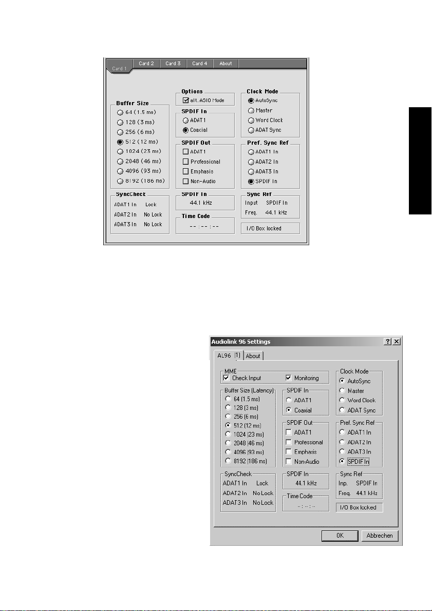
Beim Nuendo
Audiolink 96-System
arbeiten alle ADAT
optical Eingänge
(Digiset) bzw. der
ADAT optical Eingang (Multiset) und
der S/P-DIF Eingang
gleichzeitig. Da es
keinen Eingangswahlschalter gibt
muss dem System
jedoch zumindest
die Synchronisationsquelle mitgeteilt
werden (ein digitales Gerät kann seine Clock immer nur aus einem Eingang gewinnen).
Die Audiolink 96 besitzt deshalb eine automatische Clock-Eingangswahl, welche den ersten verfügbaren Eingang mit gültigem Digitalsignal als Clock-Referenz verwendet. Der jeweils aktive Eingang wird in
der Statusbox 'Sync Ref' (Synchronisations-Referenz) angezeigt, zusammen mit der aktuellen Samplefrequenz.
DEUTSCH DEUTSCH
Über 'Pref Sync Ref'
(Preferred Sync Reference – bevorzugte
Synchronisationsquelle) kann der ClockAutomatik ein Eingang
vorgegeben werden.
Dieser ist solange aktiv,
wie an ihm ein gültiges
Digitalsignal anliegt,
danach sucht die Automatik nach einem anderen. Wird gar keiner
gefunden, schaltet die
Audiolink 96 in den
Clock Modus 'Master'.
NUENDO AUDIOLINK 96
Deutsch – 97
Page 98
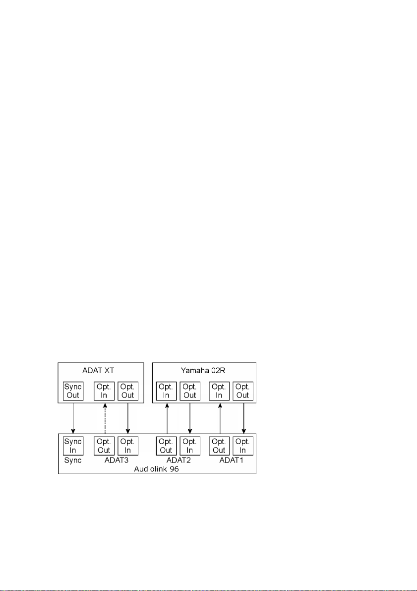
Die Vorgabe einer 'Sync Ref' ist notwendig, um im Studio jeder Situation gerecht zu werden. Dazu ein Beispiel: Am ADAT(x)-Eingang ist ein
ADAT angeschlossen (ADAT(x) wird damit sofort Sync Ref), an S/P-DIF
ein CD-Player. Nun möchten Sie kurz vom CD-Player ein paar Samples
in den Rechner einspielen – geht nicht. In den wenigsten Fällen sind
CD-Player synchronisierbar. Daher wird die Übertragung mit Störgeräuschen versehen, da das Signal des CD-Players mit der (falschen)
Clock des ADAT eingelesen wird. In diesem Fall ist also kurzfristig die
'Pref Sync Ref' auf S/P-DIF umzustellen (siehe Bild oben).
Bei gleichzeitiger Verwendung mehrerer digitaler Geräte müssen diese
nicht nur mit der gleichen Samplefrequenz arbeiten, sondern auch synchron zueinander sein. Dazu ist innerhalb des digitalen Verbundes ein
Master zu definieren, der alle weiteren Geräte mit einer (der gleichen)
Clock versorgt. Das SyncCheck-Verfahren dient der einfachen Prüfung
und Anzeige der aktuellen Clock-Situation. Die mit SyncCheck beschriftete Statusbox zeigt für die drei ADAT optical Eingänge des Digiset und
den ADAT-, S/P-DIF- und Wordclock-Eingang des Multiset jeweils getrennt an, ob kein Signal (No Lock), ein gültiges Signal (Lock), oder ob
ein gültiges und synchrones Signal anliegt (Sync). Die Anzeige der
Sync-Referenz gibt an, zu welchem Signal die Synchronität besteht.
In der Praxis erlaubt SyncCheck einen sehr schnellen Überblick über die
korrekte Konfiguration aller digitalen Geräte. Damit wird eines der
schwierigsten und fehlerträchtigsten Themen der digitalen Studiowelt
endlich für jedermann leicht beherrschbar.
Hierzu ein Beispiel, das sich auf das Digiset bezieht: Die Eingänge
ADAT1 und 2 werden von einem digitalen Mischpult gespeist, welches
im Clock Mode 'Internal' oder 'Master' arbeitet. Am Eingang ADAT3 ist
ein ADAT angeschlossen. Nuendo Audiolink 96 läuft im Modus Auto-
NUENDO AUDIOLINK 96
Deutsch – 98
Page 99

Sync. Sie werden nun feststellen, dass die Eingänge ADAT1 und 2 wie
gewünscht zueinander synchron sind (weil sie im Mischpult von einer
gemeinsamen Clock stammen), der Eingang ADAT3 jedoch nur 'Lock'
statt 'Sync' anzeigt. Da es keine Verbindung von Karte oder Mischpult
zum ADAT gibt, erzeugt dieser eine eigene Clock, welche zwar (fast) der
Samplefrequenz des Mischpultes entspricht, aber eben nicht identisch
ist. Abhilfe: Ausgang ADAT3 der Audiolink 96 mit dem Eingang des
ADAT verbinden, und diesen über seinen digitalen Eingang clocken
(DIG). Die Audiolink 96 clockt sich ja auf das Signal des Mischpultes und
gibt ein identisches (synchrones) am Ausgang ADAT3 aus. Darauf clockt sich nun der ADAT, dessen Ausgangssignal wiederum synchron ist.
Damit ist schließlich auch das Signal am Eingang ADAT 3 voll synchron
zu dem des Mischpultes.
Dank des beschriebenen AutoSync-Mechanismus und einer blitzschnellen PLL kann die Nuendo Audiolink 96 nicht nur mit den üblichen Samplefrequenzen arbeiten, sondern mit jeder Frequenz im
Bereich von 25 kHz bis 105 kHz. Als Synchronisationsquelle dient der in
'Pref Sync Ref' gewählte Eingang. Bei Verwendung des Wordclock-Einganges (Clock-Modus 'Word Clock') kann auch dieser als Synchronisationsquelle dienen. Hier ist jede Frequenz zwischen 25 kHz und 56 kHz
im Varispeed Betrieb erlaubt.
DEUTSCH DEUTSCH
Die Anzeige der aktuellen Samplefrequenz des S/P-DIF-Einganges hilft
bei Fehlersuche und richtiger Konfiguration aller digitalen Geräte. Bei
Wahl eines Einganges ohne oder mit fehlerhaftem Signal erscheint die
Angabe ‘No Lock’, im Varispeed-Betrieb oder bei stark verstimmten
Samplefrequenzen dagegen nur ‘Lock’. Auch S/P-DIF wird per SyncCheck auf Synchronität geprüft. Als Anzeige dient die LED am Digiset
bzw. Multiset (blinken bei Lock, konstant bei Sync).
Die Anzeige der S/P-DIF-Samplefrequenz unterscheidet sich bei 88,2/
96 kHz von der unter Sync Ref angezeigten, wenn einer der ADAT-Eingänge (Digiset) bzw. der ADAT-Eingang (Multiset) die aktuelle 'Sync
Ref' ist. Da ADAT optical Ein- und Ausgänge nur bis 48 kHz spezifiziert
sind geht die Karte bei 88,2/96 kHz automatisch in den Sample-SplitModus und verteilt die Daten eines Ein- und Ausganges auf jeweils
zwei Kanäle. Die interne Frequenz bleibt jedoch bei 44,1/48 kHz. Daher
ist in diesem Fall die Samplefrequenz an ADAT nur halb so hoch wie an
S/P-DIF.
NUENDO AUDIOLINK 96
Deutsch – 99
Page 100

9.3 Ändern der Jumpereinstellung – Multiset
Das Multiset besitzt intern Steckkontakte, mit denen sich die Eingangsempfindlichkeit sowie der Ausgangspegel pro Kanal einstellen lässt.
Nähere Informationen zu den verfügbaren Einstellungen enthalten die
Kapitel 8.5 und 8.6.
❐
Wir weisen ausdrücklich darauf hin, dass die Jumper nicht für ständige Än-
derungen gedacht sind. Sie sollten bei der ersten Inbetriebnahme der Studio-Situation angepasst werden, ansonsten jedoch nur geändert werden,
wenn es wirklich unvermeidlich ist. Die Werkseinstellung +4 dBu wird in
den meisten Fällen hervorragende Ergebnisse liefern.
Um die Jumperstellung zu verändern, muss das Multiset geöffnet werden. Wenn Sie sich hierbei unsicher fühlen, lassen Sie sich den Vorgang
von einem Techniker zeigen. Ansonsten folgen Sie bitte Schritt für
Schritt dieser Anleitung.
1. Entfernen Sie alle Stecker und Kabel vom Multiset.
2. Lösen und entfernen Sie die beiden Schrauben der ADAT Sync Sub-DBuchse.
3. Benutzen Sie einen Kreuzschlitzschaubendreher (Phillips 1) zum Entfernen der 6 Schrauben auf der Oberseite des Multiset, so dass der Deckel abgenommen werden kann.
4. Legen Sie das Gerät so hin, dass es mit der Frontplatte zu Ihnen zeigt. Heben Sie den Deckel an der Seite der Frontplatte vorsichtig um circa einen
Zentimeter an, und ziehen ihn dann circa zwei Zentimeter in Richtung der
Frontplatte. Bei diesem Vorgang lösen sich die oberen Klinkenbuchsen
und die Sub-D-Buchse aus der Rückwand. Der Deckel ist nun frei und kann
nach rechts umgeklappt werden.
Nutzen Sie die einmalige Gelegenheit, um sich den inneren Aufbau des Multiset anzuschauen. Auf der unteren Leiterplatte sehen Sie rechts die beiden
Schaltnetzteile, welche aus einer nahezu beliebigen Eingangsspannung sowohl 5 Volt (für die gesamte Digital-Elektronik), als auch ±13 Volt (für den analogen Schaltungsteil) erzeugen. In der Mitte befindet sich das Herz des Multiset,
das Xilinx FPGA, rechts davon DA-Wandler und analoger Schaltungsteil des
NUENDO AUDIOLINK 96
Deutsch – 100
 Loading...