

Page 1
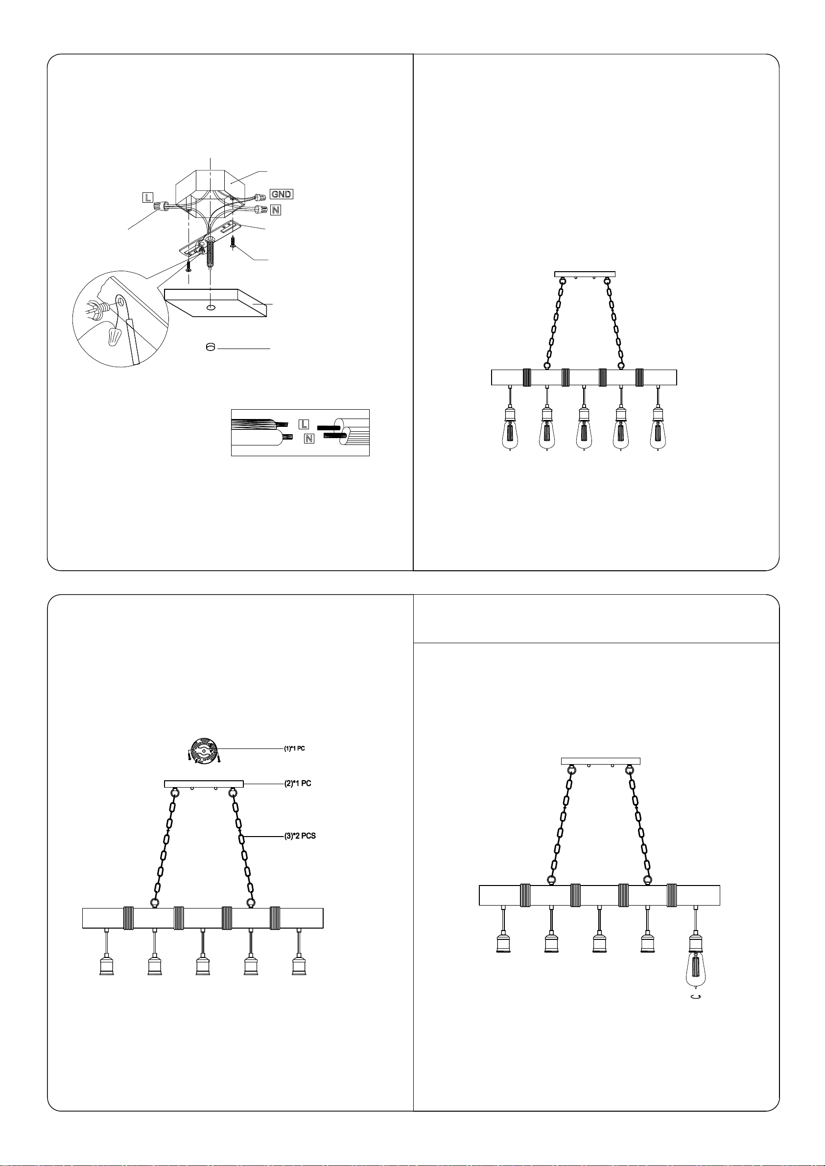
MOUNTING AND WIRING
WARNING:
Improper installation may cause electrical shock,fire, or equipment damage.
The person performing the installation must befamiliar with the construction
and operation ofthe product and associated hazards
INSTALLATION INSTRUCTIONS
F-Junction Cap
A-Existing Electrical Box
B-Crossbar
C-Crossbar Screws
E-Canopy
D-Decorative Nuts
Wire Connection Diagram:
IMPORTAN TSAFE T Y INSTRUCTIONS:
.
Please read through all the instructions carefully and completely before
beginning assembly and installation
This product must be installed in accordance with installation instructions
.
and all safety and building codes. It is strongly suggested that all direct
wiredfixtures be installed by a licensed electrician
.
Be sure the electricity to the wires you are working on is shut off; either the
use is removed or the circuit breaker is turned off. Turning the power o
f
using the light switch is not sufficient to prevent electrical shock
ff
Pl ea se proceed in an alp h ab etical ord er:
.
Attach the Round Crossbar (B) on the Electrical Box (A) with Crossbar screw (C).
.
Secure the Ground Wire on the Round Crossbar (B).
.
Connect the power source wire (L) & (N) with black & white main wire witd
Junction Cap (D).
.
Secure the fixture Canopy (F) on the Round Crossbar (B) with Decorative Nute
(E).
P A RT LIST AND ASSEMBL Y ILLUSTRATION
Note :Some parts may be pre-installed or pre-assembled.
ASSEMBLING, INSTALLATION, AND MOUNTING
 Loading...