

Page 1
The tools of innovation.
112 Inverness Circle East Suite F Englewood, CO 80112
1– 87STEELMAX, FAX 303 – 690 – 9172
OPERATOR’S MANUAL
A
A
R
R
C
C
R
Ruunnnneerr
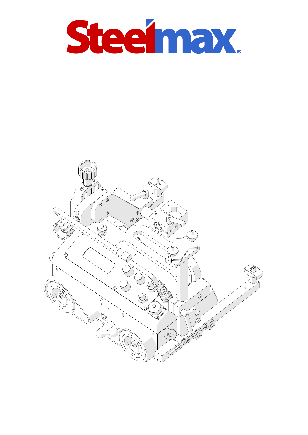
WELDING CARRIAGE
Page 2

Contents
1. GENERAL INFORMATION ................................................................................................ 3
1.1. Application ................................................................................................................. 3
1.2. Technical data............................................................................................................ 4
1.3. Equipment included ................................................................................................... 5
1.4. Dimensions ................................................................................................................ 6
1.5. Design ....................................................................................................................... 7
2. SAFETY PRECAUTIONS .................................................................................................. 8
3. STARTUP AND OPERATION...........................................................................................10
3.1. Preparing ..................................................................................................................10
3.2. Connecting to welding circuits ...................................................................................11
3.3. Positioning at the worksite ........................................................................................12
3.4. Starting .....................................................................................................................14
3.5. Programming ............................................................................................................14
3.6. Welding procedure ....................................................................................................16
3.7. Operating ..................................................................................................................17
3.8. Using oscillator (accessory) ......................................................................................18
3.9. Troubleshooting ........................................................................................................21
4. MAINTENANCE ...............................................................................................................22
5. ACCESSORIES ................................................................................................................23
5.1. Oscillator ...................................................................................................................23
5.2. Torch clamps ............................................................................................................25
5.3. Rods .........................................................................................................................26
5.4. Torch holders ................................................................................................ ............27
5.5. Torch extension arm .................................................................................................29
5.6. Guide arms ................................................................................................ ...............30
5.7. Dual torch mount .......................................................................................................35
5.8. Flexible guide set ......................................................................................................36
5.9. Guide adjustment tool ...............................................................................................38
5.10. 76 mm cross slide ...................................................................................................39
5.11. Display protection shield .........................................................................................40
5.12. Fall arrester .............................................................................................................40
5.13. Stainless steel wheels .............................................................................................41
6. 115–230 V EXPLODED VIEWS AND PARTS LIST ..........................................................42
7. 42 V EXPLODED VIEWS AND PARTS LIST ....................................................................47
8. 115–230 V WIRING DIAGRAM .........................................................................................52
9. 42 V WIRING DIAGRAM ..................................................................................................53
10. DECLARATION OF CONFORMITY ...............................................................................54
11. QUALITY CERTIFICATE ................................................................................................55
12. WARRANTY CARD ........................................................................................................56
Page 3

ARC Runner
ARC Runner Operator’s Manual
3
1. GENERAL INFORMATION
1.1. Application
The ARC Runner is a welding carriage designed to make continuous or stitch butt
and fillet welds. The carriage allows MIG/MAG torches with the handle diameter of
16–22 mm (0.63–0.87’’). It is fixed by permanent magnets and can work in the following
welding positions: PA/1F/1G, PB/2F, PC/2G, PD/4F, and PE/4G.
Accessories allow, for instance, welding with oscillation, using torches with the
handle diameter larger than 22 mm, using two torches at the same time, and guiding
the carriage along outside edges, lap joints and templates, walls low or with holes, and
on ceilings, pipes, and tanks.
Page 4
ARC Runner
ARC Runner Operator’s Manual
4
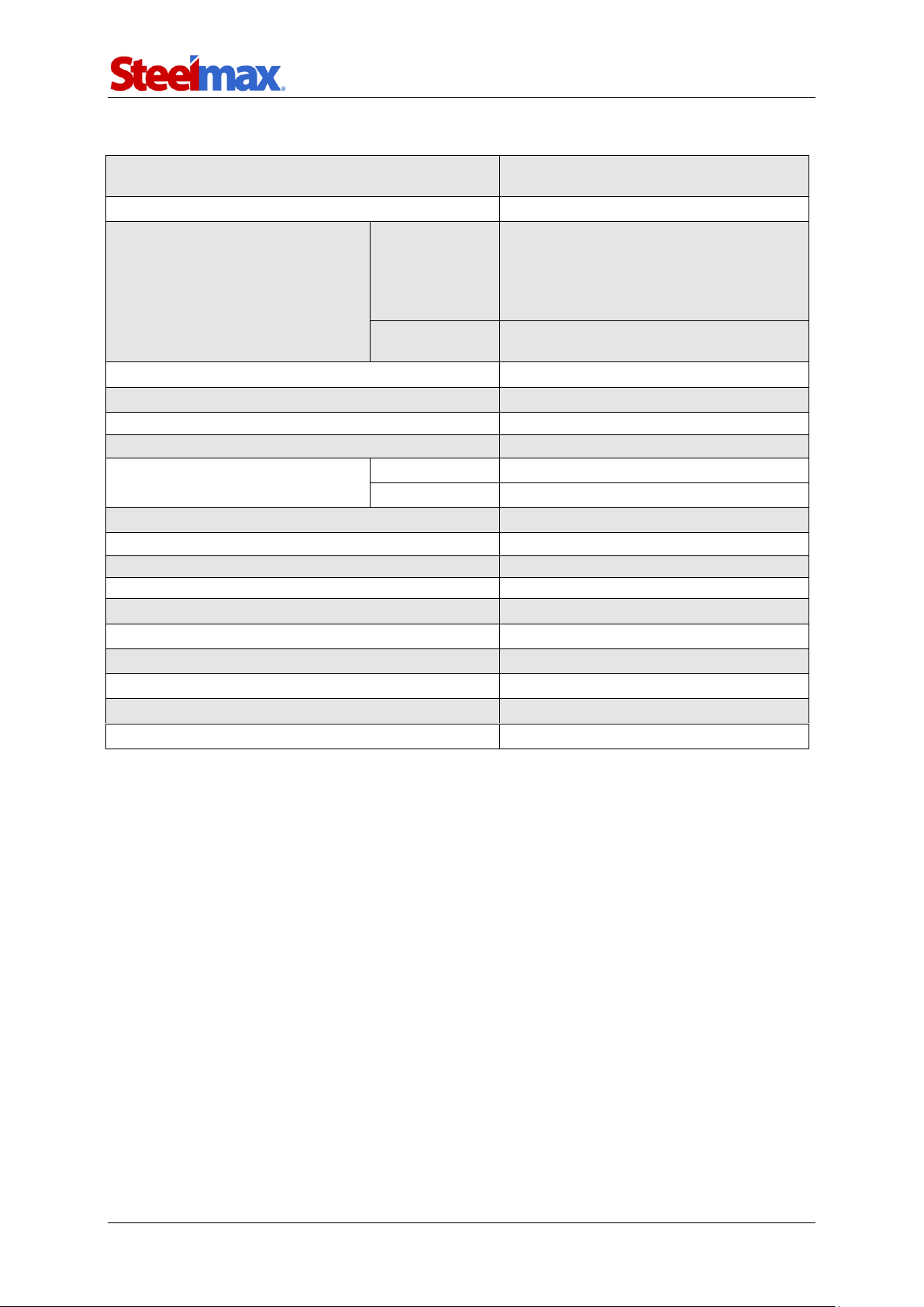
1.2. Technical data
Voltage
1~ 115–230 V, 50–60 Hz
1~ 42 V, 50–60 Hz (60 V DC)
Power
25 W
Welding position (according to
EN ISO 6947 and AWS/ASME)
Horizontal
PA / 1F / 1G
PB / 2F
PC / 2G
PD / 4F
PE / 4G
Vertical
PF / 3F / 3G (with optional oscillator)
PG / 3F / 3G (with optional oscillator)
Minimum path curve radius
1500 mm (5 ft)
Torch type
MIG/MAG
Torch diameter
16–22 mm (0.63–0.87’’)
Maximum torch reach
80 mm (3.15’’)
Maximum allowed cable weight
Horizontal work
12 kg (27 lbs)
Vertical work
8 kg (18 lbs)
Minimum workpiece thickness
5 mm (0.20’’)
Ground clearance
5 mm (0.20’’)
Horizontal pulling force
220 N (48 lbs)
Vertical pulling force
150 N (33 lbs)
Cross slide adjustment range
0–35 mm (0–1.38’’, up-down, left-right)
Guide arm adjustment range
0–75 mm (2.95’’)
Horizontal speed
0–120 cm/min (0–47.2 in/min)
Vertical speed
0–110 cm/min (0–43.3 in/min)
Noise level
Less than 70 dB
Weight
14 kg (31 lbs)
Page 5
ARC Runner
ARC Runner Operator’s Manual
5
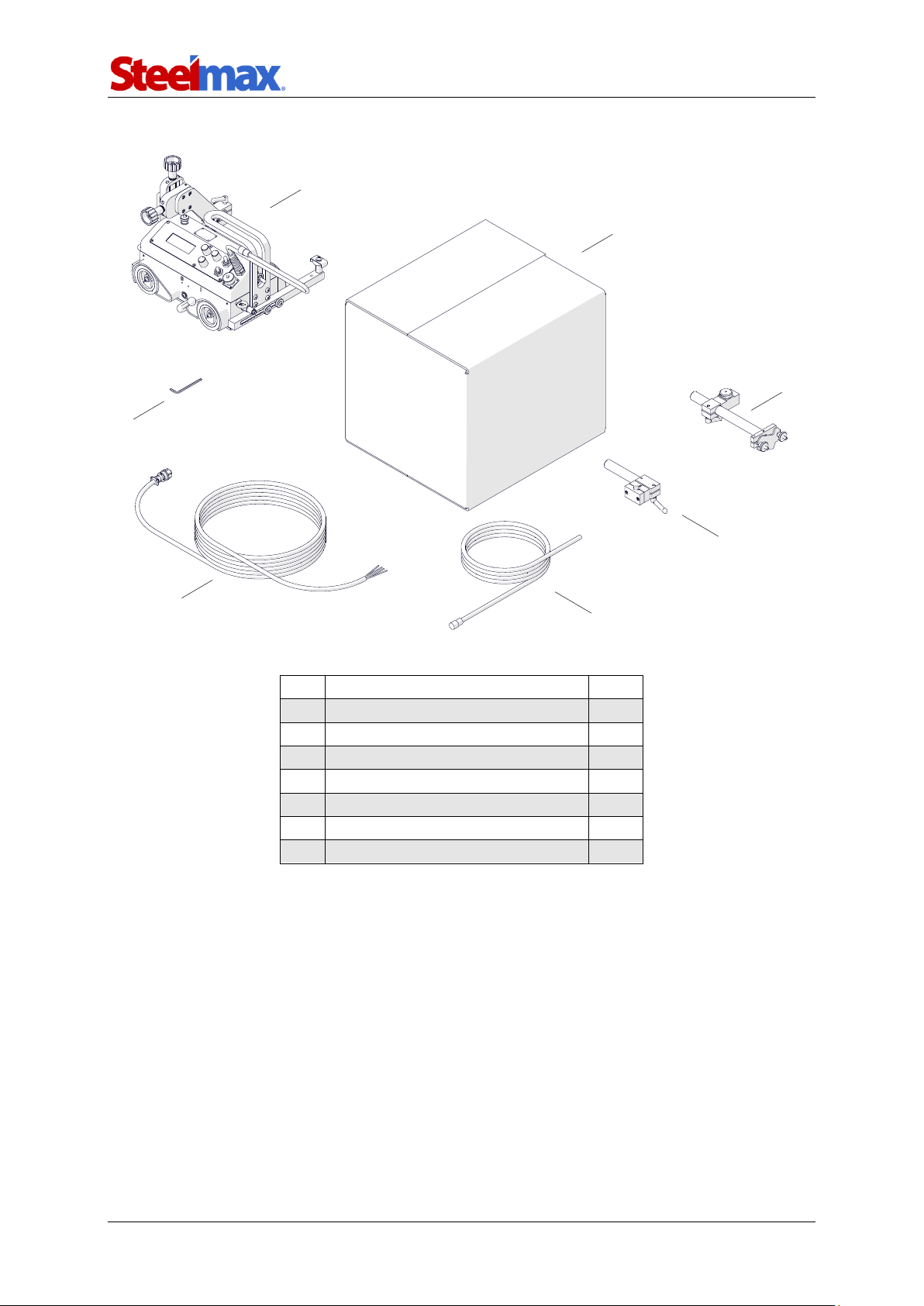
1.3. Equipment included
1
Carriage
1 unit
2
Foam-filled cardboard box
1 unit
3
Cable anchor
1 unit
4
Short rod torch holder with clip
1 unit
5
3 m (10 ft) power cord
1 unit
6
6.5 m (21 ft) arc ignition cable
1 unit
7
4 mm hex wrench
1 unit
–
Operator’s Manual
1 unit
1
2 3 4 5 6
7
Page 6
ARC Runner
ARC Runner Operator’s Manual
6
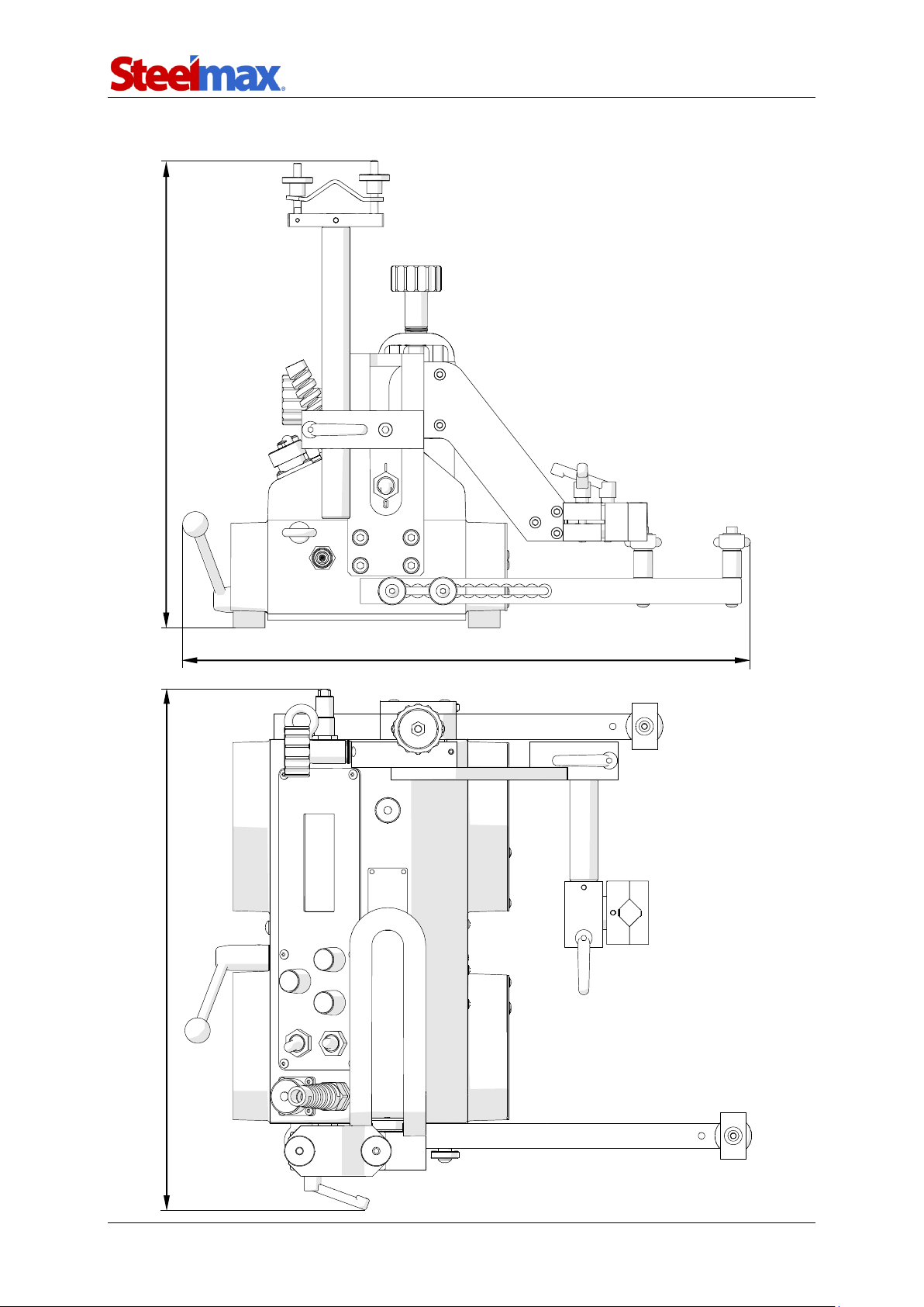
1.4. Dimensions
411 mm (16.2’’) 368 mm (14.5’’)
447 mm (17.6’’)
Page 7
ARC Runner
ARC Runner Operator’s Manual
7
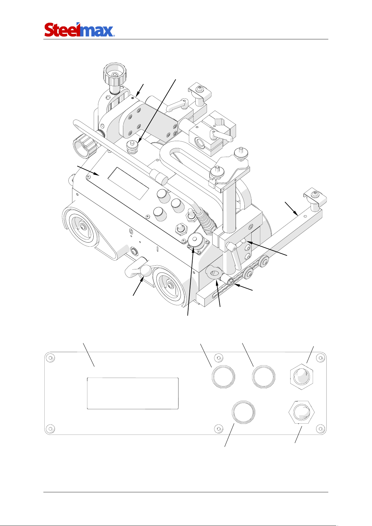
1.5. Design
Lug for fall arrester
Arc ignition socket
Control panel
Cross slide
Oscillation socket
Guide arm
Power switch
Limit switch
Magnet ON/OFF lever
LCD display
Knob F1
Knob F2
Arc ignition switch
(TEST / O / I)
Travel direction switch
(Left / O / Right)
Speed adjustment knob
Page 8

ARC Runner
ARC Runner Operator’s Manual
8
2. SAFETY PRECAUTIONS
1. Before starting, read this Operator’s Manual and complete proper occupational
safety and health training.
2. Use the carriage only in applications specified in this Operator’s Manual.
3. The carriage must be complete and all parts must be genuine and fully functional.
4. The specifications of the power source must conform to those specified on the
rating plate.
5. Connect the carriage into a properly grounded power source.
6. Never carry the carriage by the cords or arc ignition cable. Never pull them
because this may damage them and result in electric shock.
7. Untrained bystanders must not be present near the carriage.
8. Before starting, ensure the correct condition of the carriage, power source, cords,
arc ignition cable, plugs, control panel, and wheels.
9. Keep the carriage dry, and never expose it to rain, snow, or frost.
10. Keep the work area well lit, clean, and free of obstacles.
11. Never use near flammable liquids or gases, or in explosive environments.
12. Make sure that the rubber of the wheels is clean and not damaged.
13. Never remove the cover of the wheels.
14. Remove objects attracted to the chassis by the magnet.
15. Transport and position the carriage by using the carrying handle and only when
the magnet ON/OFF lever is set to ‘O’.
16. Position the carriage on the ferromagnetic workpiece so that the wheels are in
contact with the surface and no contact is between the surface and chassis.
17. Do not stay below the carriage placed at heights.
18. Plug the cords and arc ignition cable only when the power switch is set to ‘O’.
19. Keep the sockets clean. Do not use compressed air for cleaning.
20. Install only MIG/MAG torches whose handle diameter is the same as the diameter
of the torch holder in use.
21. Do not position the torch more than 80 mm (3.15’’) outward from the left or right
side of the carriage.
22. Keep the torch cables from coming in contact with the surface. They must be
suspended to reduce the load of the carriage. Use only cables whose weight is
not more than 12 kg (27 lbs) for horizontal work and 8 kg (18 lbs) for vertical work.
Page 9

ARC Runner
ARC Runner Operator’s Manual
9
23. Never work on curves with convex or concave radius less than 1500 mm (5 ft).
24. At heights, use a fall arrester to protect the carriage from falling.
25. Always use eye protection (helmet, shield, and screen), hearing protection, gloves,
and protective clothing during work. Do not wear loose clothing.
26. Before every use, inspect the carriage to ensure it is not damaged. Check whether
any part is cracked or improperly fitted. Make sure to maintain proper conditions
that may affect the operation of the carriage.
27. Never try to manually stop the travel. To stop, set the travel direction switch to ‘O’.
28. Maintain only when the carriage is unplugged from the power source.
29. Repair only in a service center appointed by the seller.
30. If the carriage falls from any height, is wet, or has any other damage that could
affect the technical state of the carriage, stop the work and promptly send the
carriage to the service center for inspection and repair.
31. Never leave the carriage unattended during work.
32. Remove from the worksite and store in a secure and dry place when not in use.
Page 10
ARC Runner
ARC Runner Operator’s Manual
10
3. STARTUP AND OPERATION
3.1. Preparing
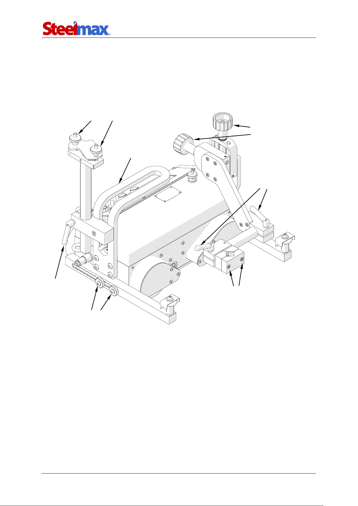
Use the carrying handle to transport the carriage to the worksite. Then, set to ‘O’ all
switches (power, travel direction, and arc ignition switch) and the magnet lever.
Fig. 1. View from the back side
Connect the carriage to the power source, insert the torch into the torch holder, and
then secure it with the screws with the 4 mm hex wrench. Next, insert the torch cable
into the cable anchor, secure it with the knobs, and then fix the anchor in the required
position with the lever.
Precise torch position
adjustment knobs
Knobs securing the cable in the anchor
Lever securing
the cable anchor
Screws securing the torch in the holder
Levers securing the torch
position and angle
Screws securing the guide arm
Carrying handle
Page 11
ARC Runner
ARC Runner Operator’s Manual
11
3.2. Connecting to welding circuits
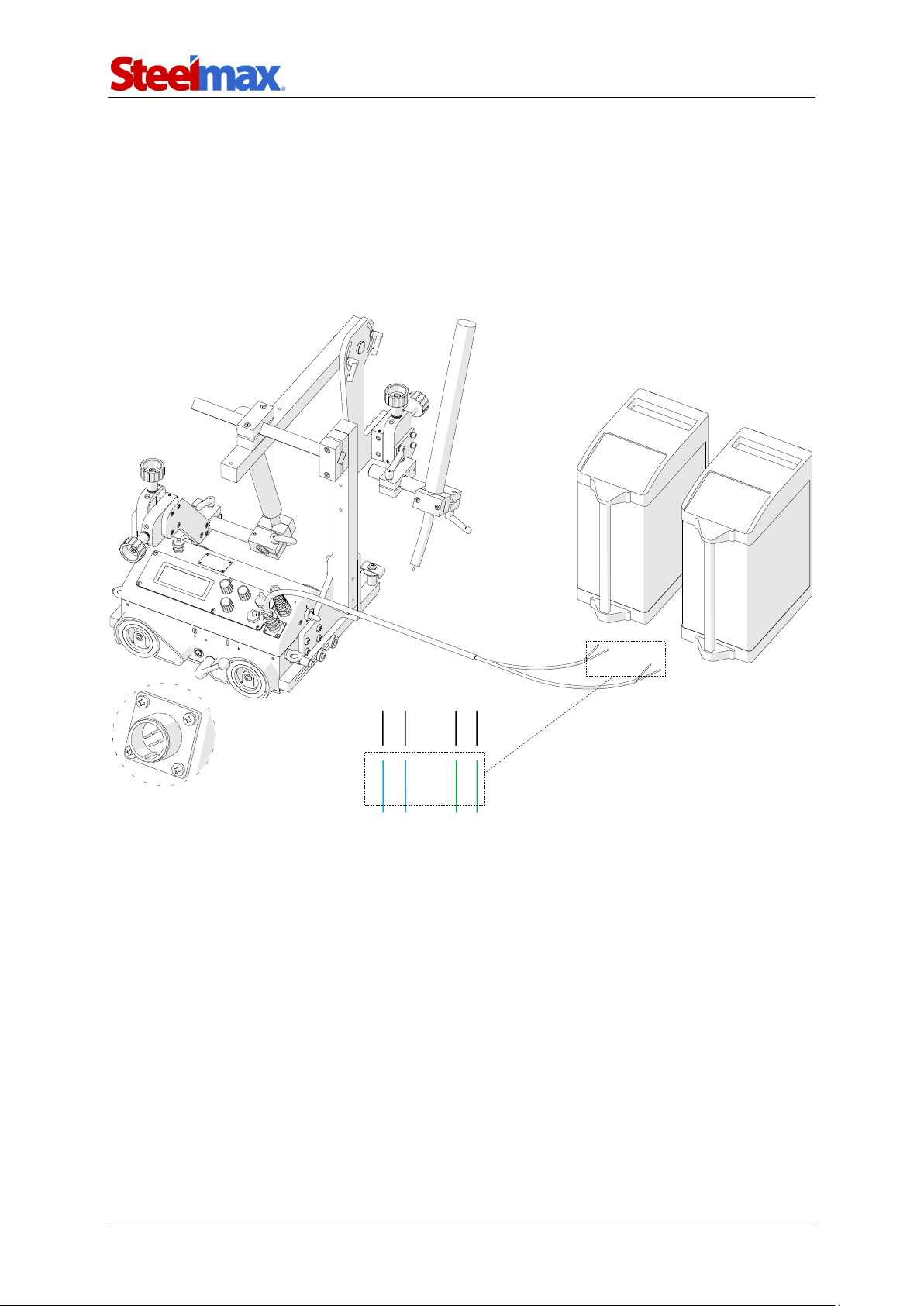
The carriage can control two torches by using the arc ignition cable plugged into the
arc ignition socket. To do this, according to the diagram shown in Fig. 2 connect
any blue-jacketed wire to any terminal of the welding circuit. Then, connect the second
blue-jacketed wire to the second terminal of the same circuit. To control the second
torch, connect the green-jacketed wires to the terminals of the second welding circuit.
Fig. 2. Connecting the arc ignition cable to welding circuits
To make sure that the arc ignition cable is connected correctly, turn on the power of
the carriage, and then set the arc ignition switch to the position TEST. This should
enable the arc for a while.
blue blue
Welding circuit 1
green
green
Welding circuit 2
Page 12
ARC Runner
ARC Runner Operator’s Manual
12
3.3. Positioning at the worksite
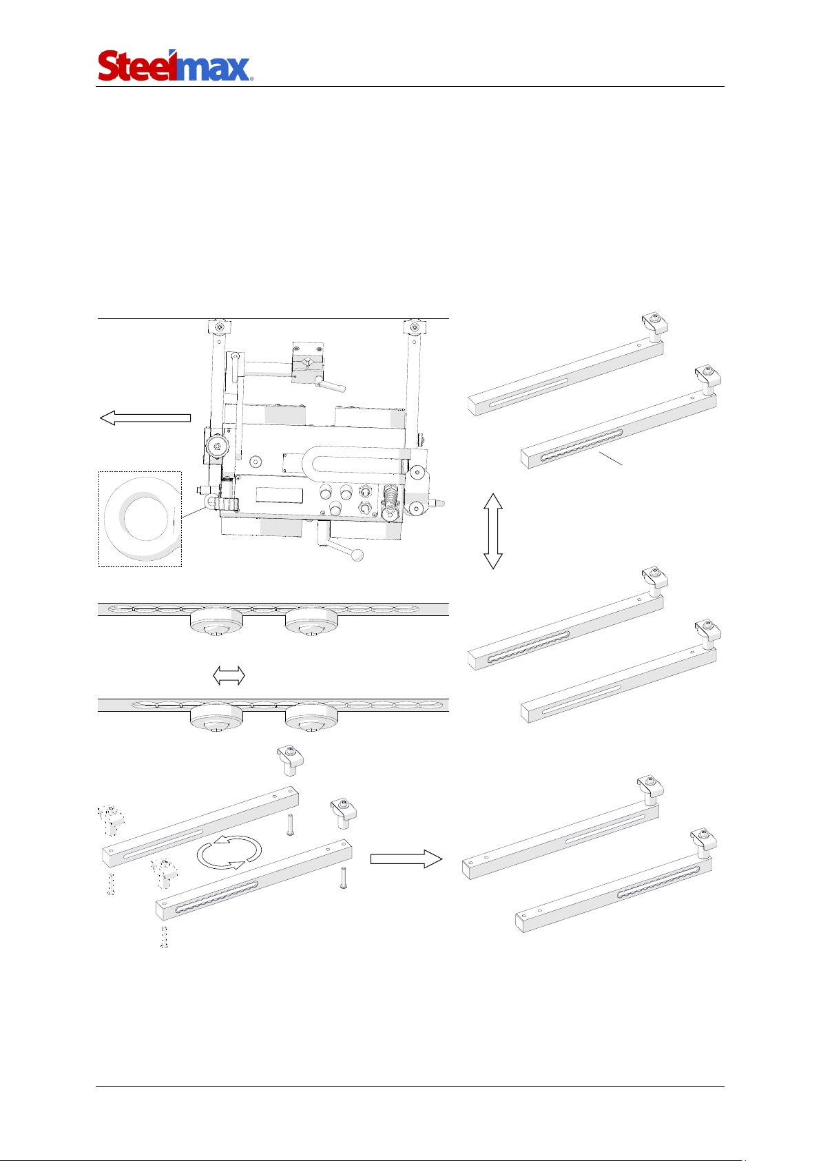
The guide arms must be positioned so that the carriage is in constant contact with the
workpiece. They can be set by a constant step (interval adjustment), or continuously
after they are swapped (continuous adjustment). To set them properly when the carriage
travels to the left, use the 4 mm hex wrench to loosen the screws securing the right
guide arm. Next, move out the right arm about 10 mm (0.4’’) or one groove more than
the left arm (Fig. 3), and then retighten the screws.
Fig. 3. Proper positioning of the guide arms
The roller assemblies may be installed at
the other end of the guide arms
Interval adjustment
Travel direction
Continuous adjustment
Swap the guide arms
to change between
methods of adjustment
Grooves
Moving out the right arm
by one groove
Lug for fall arrester
Page 13

ARC Runner
ARC Runner Operator’s Manual
13
To position the carriage closer to the workpiece, use the 3 mm hex wrench to
unscrew the roller assemblies. Next, install them at the other end of the guide arms,
and then swap the guide arms (Fig. 3).
Switch the magnet ON/OFF lever from left (‘O’) to right (‘I’). This will change the
clamping force from minimum to maximum. Loosen the levers to adjust the position
and angle of the torch. Use two knobs at the cross slide to precisely set the torch
position.
At heights, attach a fall arrester (not included) to a lug (Fig. 3) to prevent the
carriage from falling. This will avoid possible injury to the operator in case the carriage
loses the clamping. Do not stay below the carriage placed at heights.
Page 14
ARC Runner
ARC Runner Operator’s Manual
14
3.4. Starting
Plug the power cord into the power source and set the power switch to ‘I’ to turn on
the power. Then, an initial screen with the current firmware number appears, and the
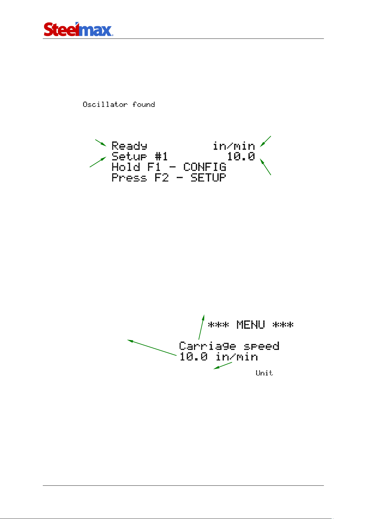
carriage checks for an oscillator connected to the oscillation socket. If the oscillator is
connected, appears. After the control system is loaded, the
main menu from Fig. 4 appears.
Fig. 4. Example of the main menu
Press and hold the knob F1 for about 3 seconds to go into the configuration
menu and set the welding parameters.
3.5. Programming
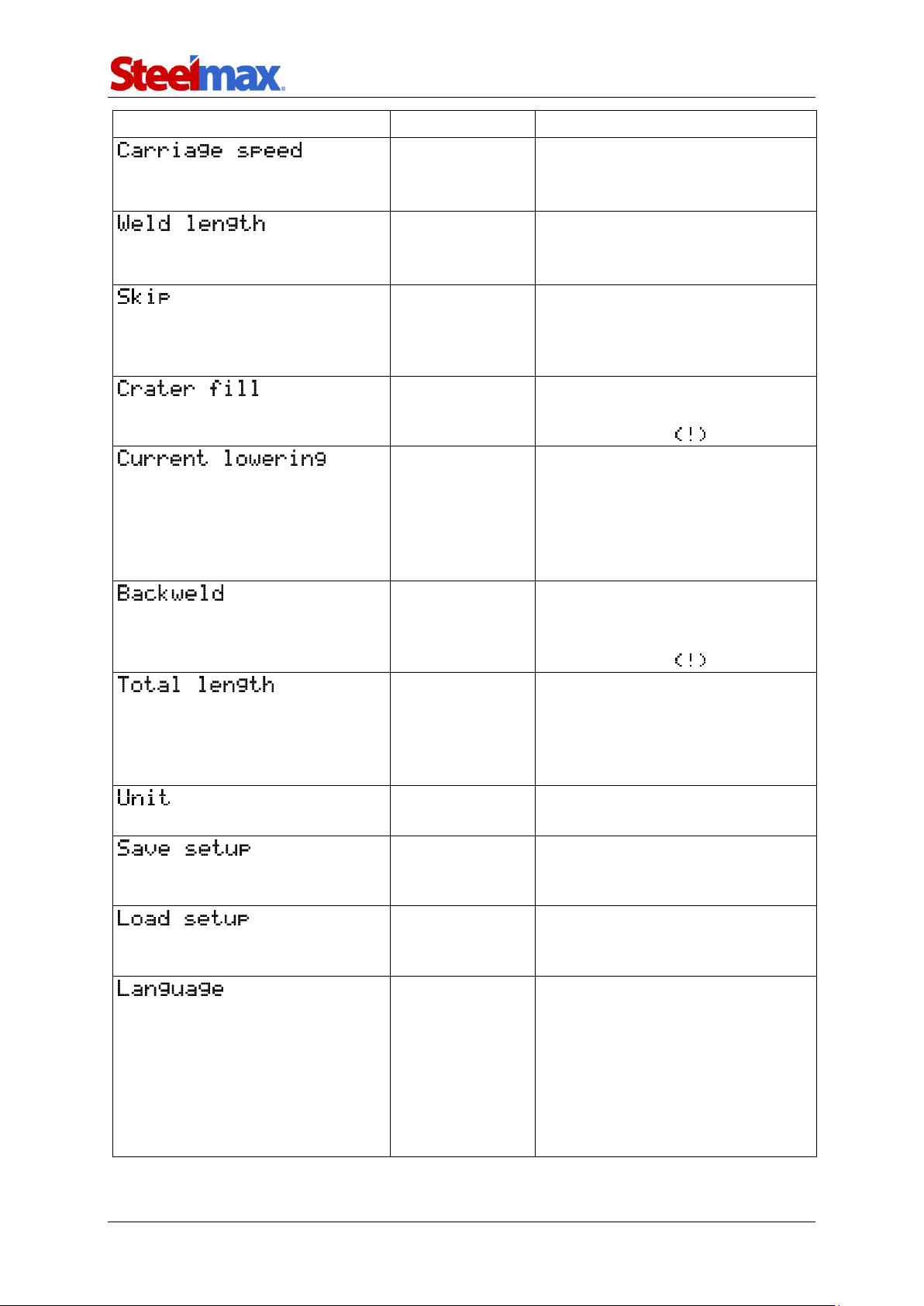
The ARC Runner welding carriage allows defining up to 40 welding programs. After
going into the configuration menu, proceed as described in Fig. 5 to move among the
parameters from Tab. 1.
Fig. 5. Configuration menu
Current operating state
Program
number
Unit of speed
Value of speed
Name of parameter. Rotate the knob F1 to change
among parameters listed in Tab. 1.
Value of parameter. Rotate the knob
F2 to change the value by the higher
step indicated in Tab. 1. Press and
rotate the knob F2 to change the
value by the lower step.
Unit of parameter. Can be changed from the setting.
Page 15
ARC Runner
ARC Runner Operator’s Manual
15
Parameter
Value
Description
0–130 cm/min
0–52 in/min
[step: 1 or 0.1]
Speed of the carriage.
1–250 cm
1–100 in
[step: 1 or 0.1]
Length of the single weld.
0–100 cm
0–40 in
[step: 1 or 0.1]
Space between welds. If set to
zero, ‘crater fill’ and ‘backweld’
are reset and the carriage works
in the continuous welding mode.
0–3 s
[step: 0.1]
Time of filling the crater. Inactive
if ‘skip’ set to zero, which is
indicated by the sign.
YES
NO
Function of the welding source to
lower the current of the arc while
filling the crater. Time of filling the
crater must be set higher or equal
to the time of the current lowering
that is set at the welding source.
0–2 cm
0–2 in
[step: 0.1]
Length of the backweld. Shorter
or equal to ‘weld length’. Inactive
if ‘skip’ set to zero, which is
indicated by the sign.
0–1000 cm
0–400 in
infinity
[step: 10 or 1]
Longer or equal to the sum of
‘weld length’ and ‘skip’. If set to
infinity, the program executes
until the carriage is stopped
manually.
cm
in
Unit used in the menu.
1–40
Pressing knob F2 saves the
current configuration under the
indicated program number.
1–40
Pressing knob F2 loads the
configuration saved under the
indicated program number.
ENGLISH
POLISH
SPANISH
FRENCH
PORTUGUESE
TURKISH
GERMAN
RUSSIAN
Language of the menu.
Tab. 1. Settings available in basic version of ARC Runner
Page 16
ARC Runner
ARC Runner Operator’s Manual
16
To change the language of the menu, go to setting by rotating the
knob F1 to the right and then rotate the knob F2 to choose among the available
languages. After the rest of the parameters from Tab. 1 is set, go to ,
choose a program number by rotating the knob F2, and press the knob to save the
current values under this number. The action is confirmed by showing message
for a short time. To load a previously saved program, proceed as described, but from
setting. Then, to go back to the main menu (Fig. 4), press the knob F1
and hold it for 3 seconds. If the chosen parameters are not saved, they will be active
only until the current program number is changed in the main menu.
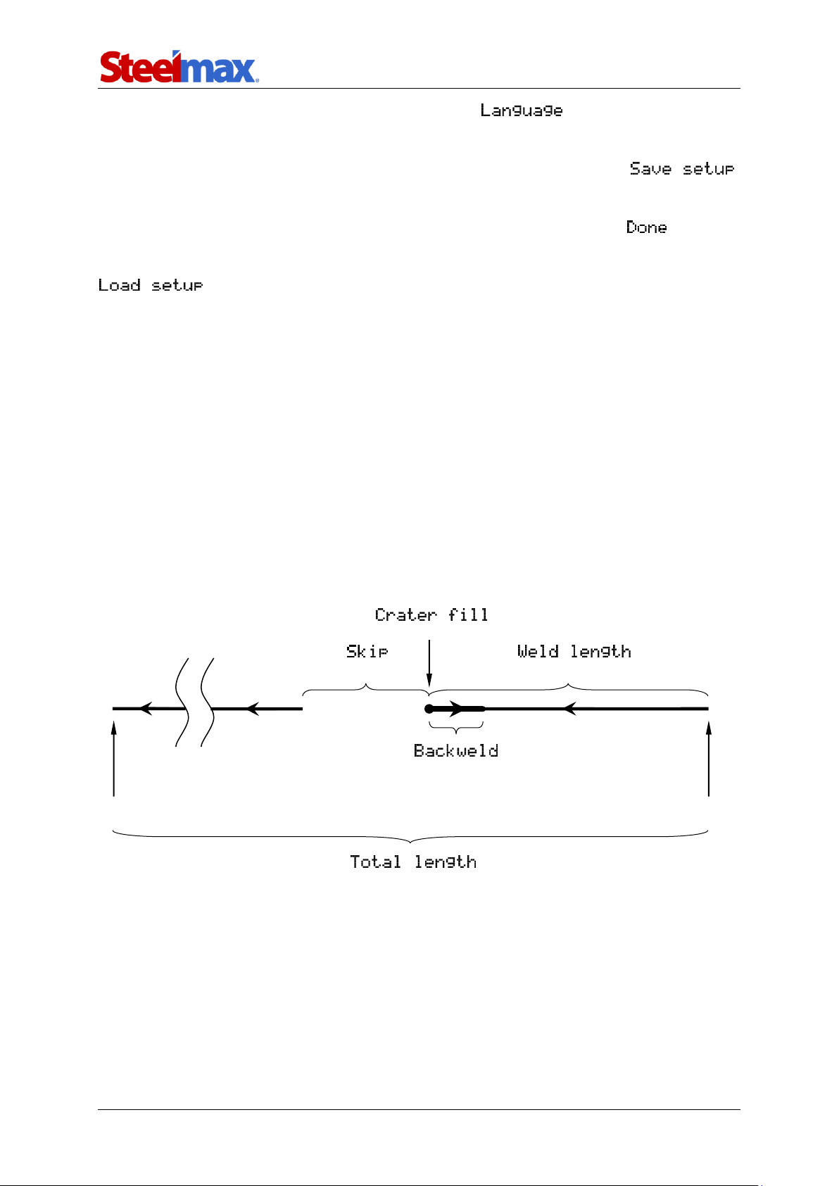
3.6. Welding procedure
Fig. 6 shows a graphic description of the welding procedure that starts with the speed
value shown in the main menu when selecting a travel direction. The first stage
involves producing the weld, after which the carriage fills the crater (stage 2) for the
chosen time. Next, the carriage performs the backweld (stage 3) and then moves to
the starting point of the next weld (stage 4). This process is repeated until the carriage
reaches the value of the total length.
Fig. 6. Visualization of the welding procedure according to parameters from Tab. 1
(stage 1)
(stage 3)
Starting point of the first weld
(stage 2)
(stage 4)
Final point of the welding procedure
Page 17

ARC Runner
ARC Runner Operator’s Manual
17
3.7. Operating
Set the power switch to ‘I’ to turn on the carriage. To control the torch via the carriage,
set the arc ignition switch to ‘I’.
With state shown on the main menu (Fig. 4) the current program
can be changed by pressing and rotating the knob F2. Use the speed adjustment
knob to change the current welding speed. Right rotation increases the speed by the
step of 0.1, and left rotation decreases the speed by the same step.
Use the travel direction switch to select a direction of travel. The carriage will
start moving according to the chosen program parameters. The indication of the current
operating mode will show on the display during program execution. The carriage
speed can be changed during work with the speed adjustment knob. The new speed
will be saved only if the current program does not change in the meantime.
The carriage stops after reaching the total length and message
shows on the display. Then, set the travel direction switch to ‘O’ to go into the main
menu. After the work is finished, use the power switch to turn off the power, and then
unplug the carriage from the power source.
If the arc ignition switch is set to ‘I’, the torch will start welding
promptly after selecting a travel direction.
Page 18
ARC Runner
ARC Runner Operator’s Manual
18
3.8. Using oscillator (accessory)
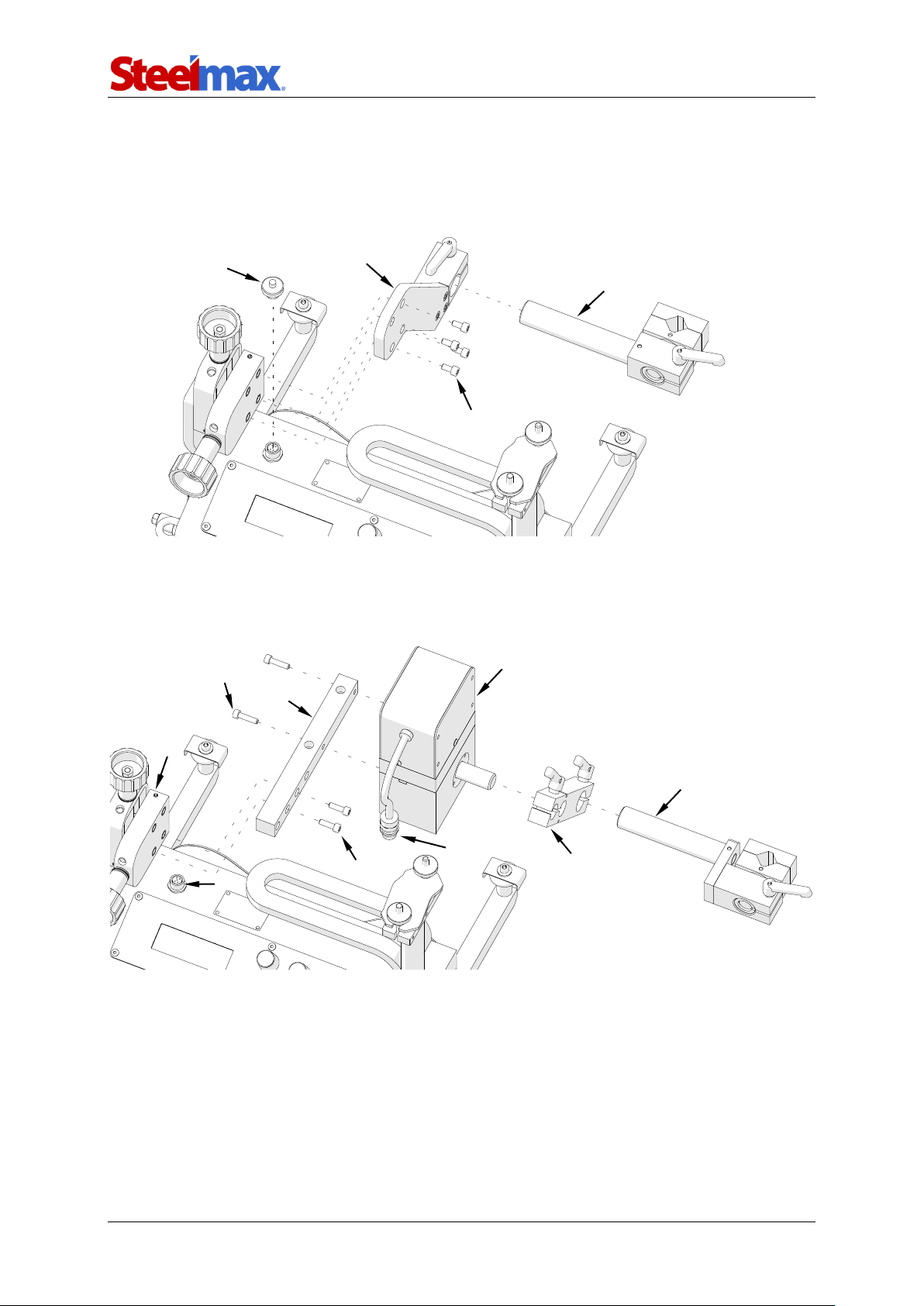
3.8.1. Installing
Install the oscillator according to the following instructions.
• Remove the torch holder 1.
• Remove the torch holder plate 2 by unscrewing screws 3 with 4 mm hex wrench.
• Unscrew the cap 4.
• Fix the arm 5 to the oscillator 6.
• Fix the oscillator 6 to the bracket 7 with two M5x20 screws 8.
• Fix the bracket 7 to the cross slide 10 with two M5x16 screws 9.
• Fix the oscillator plug 11 to the oscillation socket 12.
• Fix the low torch holder 13 to the oscillator arm 5.
4 2 3 1 8 7 9
12
10 6 11 5 13
Page 19
ARC Runner
ARC Runner Operator’s Manual
19
3.8.2. Welding with oscillation
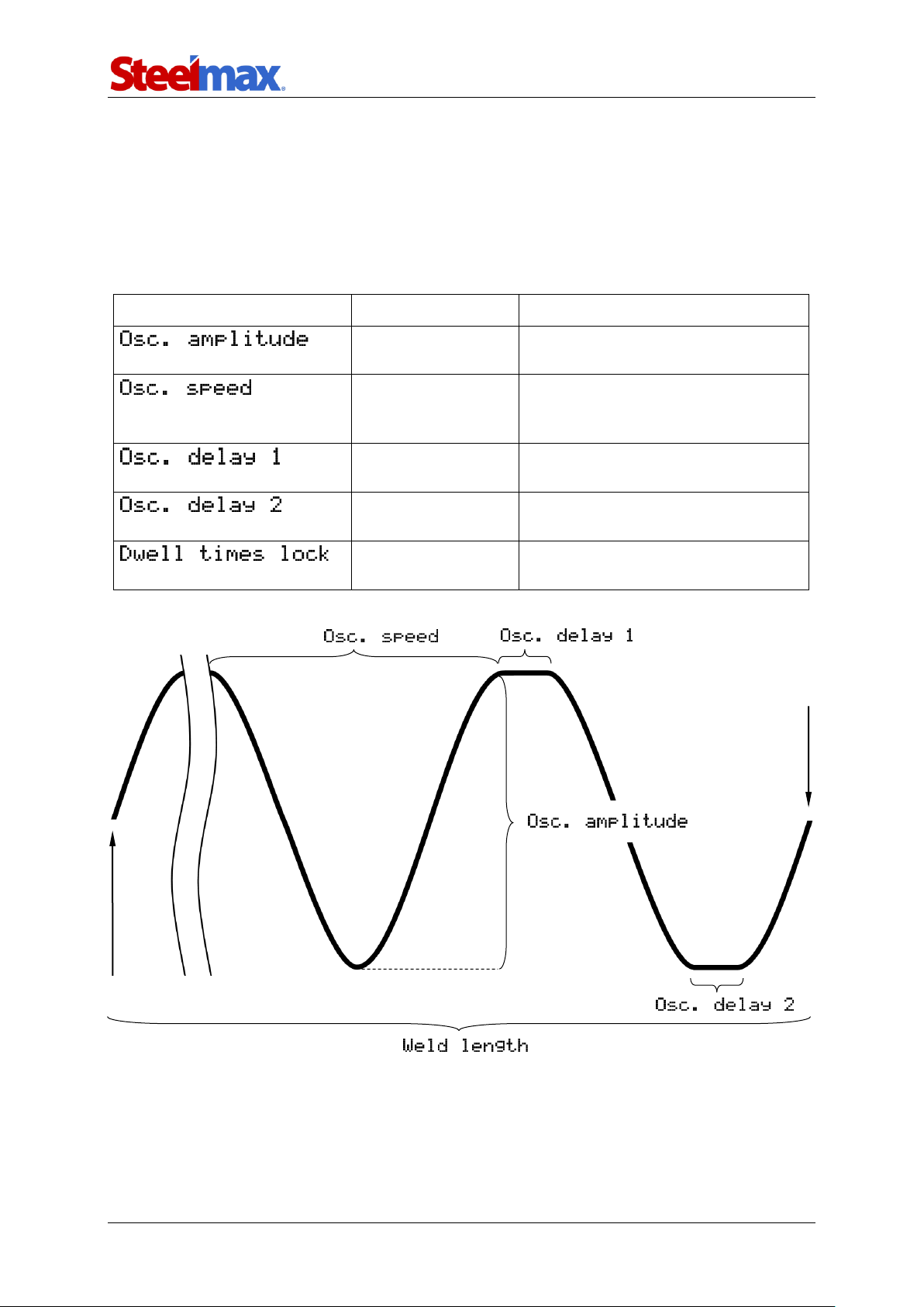
If the oscillator is connected to the ARC Runner welding carriage, several new
settings will appear in the menu (Tab. 2). Welding with oscillation is performed in the
standard manner; however, produced welds form a shape similar to the shape shown
in Fig. 7 instead of the straight line from Fig. 6.
Parameter
Value
Description
0–100%
[step: 10% or 1%]
Relative amplitude of the oscillation.
0–100%
[step: 10% or 1%]
Relative speed of the oscillation. The
higher the speed, the shorter the
oscillation period.
0–5 s
[step: 1 or 0.1]
Dwell time in the top position of the
oscillation.
0–5 s
[step: 1 or 0.1]
Dwell time in the bottom position of
the oscillation.
YES
NO
Choosing YES locks the capability of
changing dwell times during welding.
Tab. 2. Additional settings available with connected oscillator
Fig. 7. Graphic description of the oscillation parameters from Tab. 2
Starting point of the weld
Final point of the weld
1 /
Page 20
ARC Runner
ARC Runner Operator’s Manual
20
3.8.3. Operating
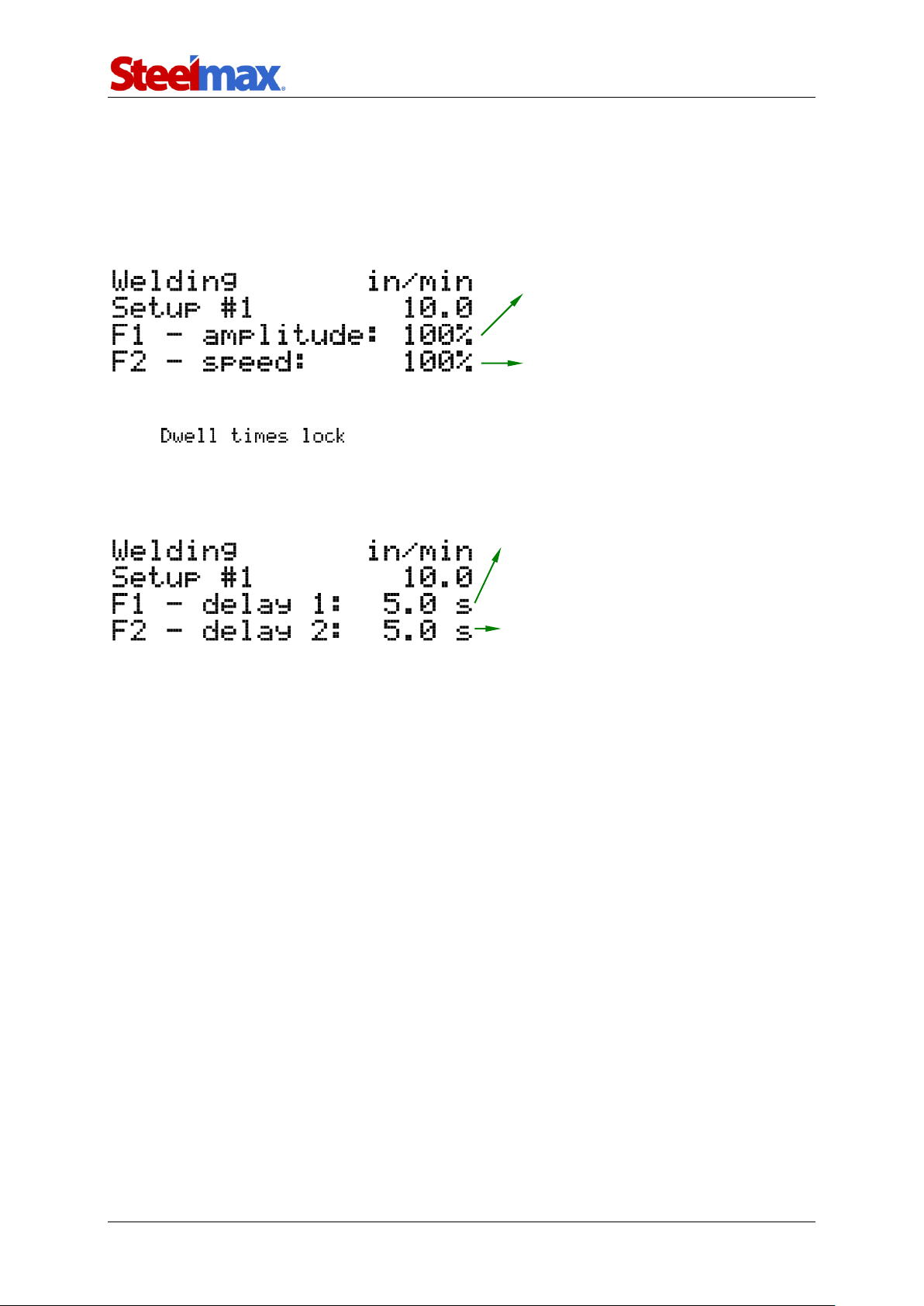
The ARC Runner welding carriage with connected oscillator is operated similarly to
operating without the oscillator. During welding with the oscillator, the menu indicated
in Fig. 8 is shown on the display.
Fig. 8. Menu shown during welding with the oscillator
If parameter is set to YES, pressing the knob F1 or F2
during work will not trigger any action. Otherwise, the delay parameters will show on
the display and can be adjusted online (Fig. 9).
Fig. 9. Menu for changing the oscillator dwell times
Rotation of the knob F1 changes the
oscillation amplitude by 1%.
Rotation of the knob F2 changes the
oscillation speed by 1%.
Rotation of the knob F2 changes the delay 2
by 0.1 s. Pressing the F2 switches from
showing delay 2 to oscillation speed.
Rotation of the knob F1 changes the delay 1
by 0.1 s. Pressing the F1 switches from
showing delay 1 to oscillation amplitude.
Page 21
ARC Runner
ARC Runner Operator’s Manual
21
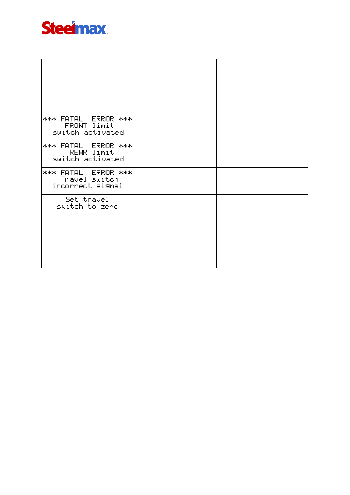
3.9. Troubleshooting
Problem
Cause
Solution
Dark LCD display after
powering.
Malfunction of the power
cord, power switch, power
supply unit, or controller.
Contact service center for
inspection and repair.
Anomalies on the LCD display.
Values illegible.
Malfunction of the display
or power supply unit.
Contact service center for
inspection and repair.
Carriage reached the
obstacle at the front.
Remove the obstacle blocking
the travel or choose the
opposite travel direction.
Carriage reached the
obstacle at the rear.
Remove the obstacle blocking
the travel or choose the
opposite travel direction.
Too fast switching between
left and right travel
direction.
Set the travel direction switch
to ‘O’.
1. Travel direction switch
not set to ‘O’ when
powering.
2. Displayed during travel
indicates a malfunction of
the travel direction switch
or travel direction
identification circuit of the
controller.
1. Set the travel direction
switch to ‘O’.
2. Contact service center for
inspection and repair.
Page 22

ARC Runner
ARC Runner Operator’s Manual
22
4. MAINTENANCE
Daily:
1. Clean the chassis and wheels.
2. Clean the rollers of the guide arms and make sure that the rollers rotate freely.
3. Clean the torch nozzle. Replace if damaged.
Monthly:
1. Check whether the knobs and the switches work as intended. Replace if loose
or damaged.
2. Inspect cables, cords, and hoses. Replace if damaged.
3. Tighten screws if loose.
Page 23
ARC Runner
ARC Runner Operator’s Manual
23
5. ACCESSORIES
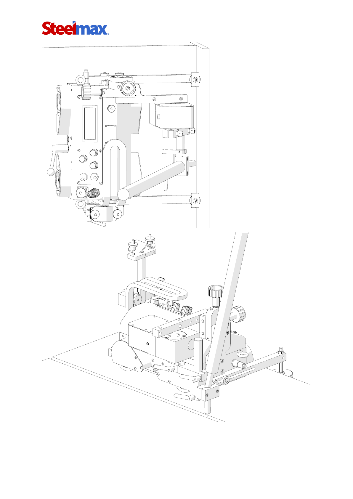
5.1. Oscillator
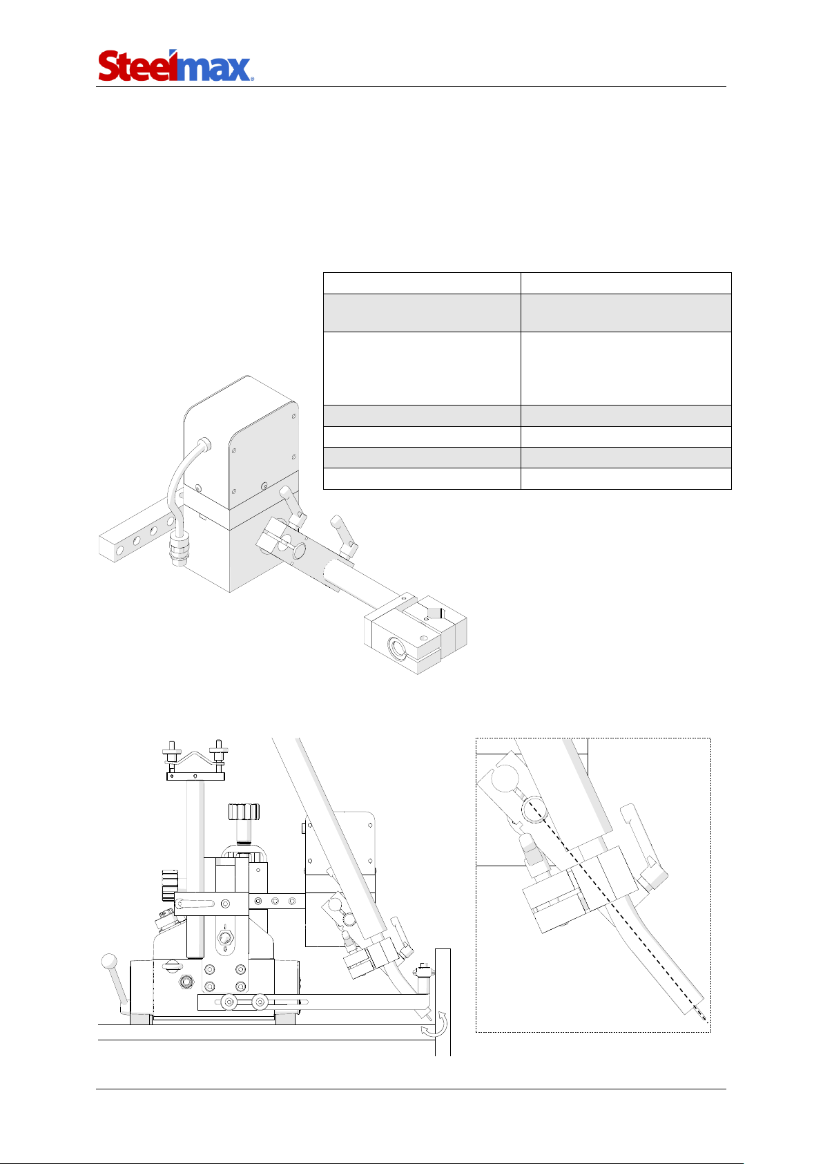
Allows welding with oscillation. Can be installed either vertically to use a short rod
low torch holder with clip (included) or horizontally to use a torch holder with clip (in
standard).
Oscillation type
Pendulum (maximum 11°)
Oscillation amplitude at
r=150 mm (5.9’’)
1–30 mm (1–100%)
Oscillation speed at
oscillation amplitude of
10 mm (0.4’’) and zero
dwell time on ends
7–164 cycles/min (1–100%)
Dwell time on ends
0–5 s
Maximum torque
5 Nm (3.7 lb·ft)
Power
12 W
Weight
2.6 kg (5.7 lbs)
To obtain the proper shape of oscillation, the axis of the oscillator’s output shaft
must cross with the axis of the torch.
Part number:
ZSP-0477-24-00-00-0
(includes: short rod low
torch holder with clip)
Page 24
ARC Runner
ARC Runner Operator’s Manual
24
Page 25
ARC Runner
ARC Runner Operator’s Manual
25
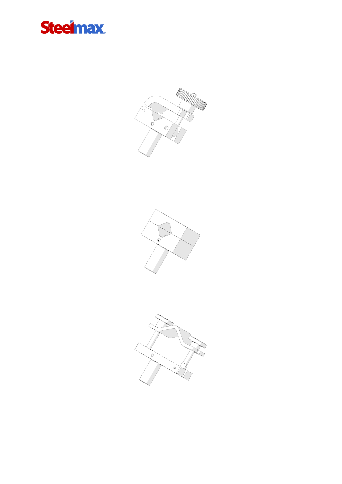
5.2. Torch clamps
5.2.1. 16–22 mm torch clamp
Allows using a torch with the handle diameter of 16–22 mm (0.63–0.87’’).
5.2.2. 16–22 mm torch clip
Allows using a torch with the handle diameter of 16–22 mm (0.63–0.87’’). Use the
4 mm hex wrench to tighten the torch in the clip.
5.2.3. 22–35 mm torch clamp
Allows using a torch with the handle diameter of 22–35 mm (0.87–1.38’’).
Part number:
ZRZ-0466-19-00-00-0
Part number:
ZRZ-0466-04-01-00-0
Part number:
ZCS-0476-06-01-00-0
Page 26
ARC Runner
ARC Runner Operator’s Manual
26
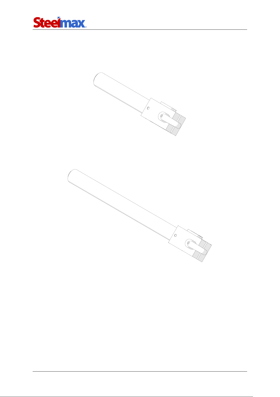
5.3. Rods
5.3.1. Short rod
Provides a 120 mm (4.72’’) reach.
5.3.2. Long rod
Provides a 240 mm (9.45’’) reach.
Part number:
WLK-0476-20-01-00-0
Part number:
WLK-0466-04-10-00-0
Page 27
ARC Runner
ARC Runner Operator’s Manual
27
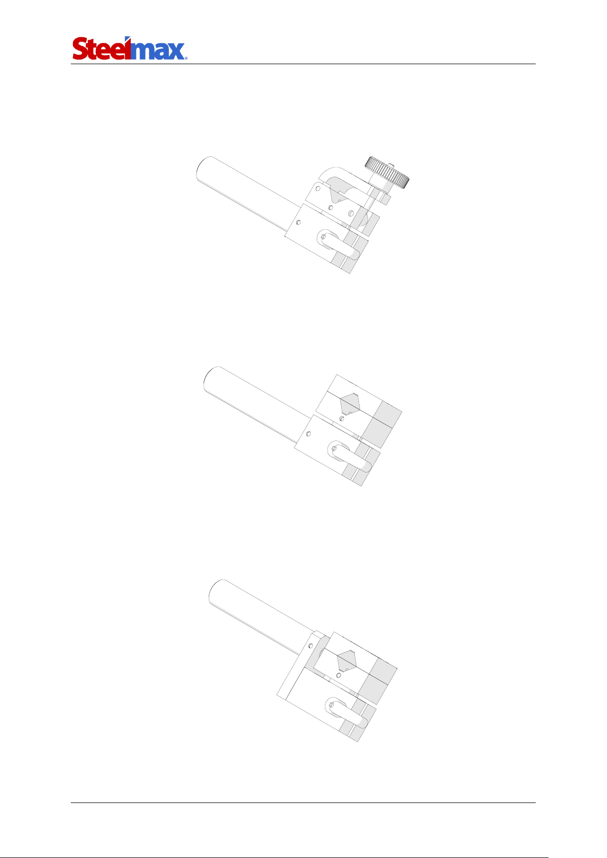
5.4. Torch holders
5.4.1. Short rod torch holder with clamp
Allows using a torch with the handle diameter of 16–22 mm (0.63–0.87’’).
5.4.2. Short rod torch holder with clip
Allows using a torch with the handle diameter of 16–22 mm (0.63–0.87’’). Use the
4 mm hex wrench to tighten the torch in the clip.
5.4.3. Short rod low torch holder with clip
Allows using a torch with the handle diameter of 16–22 mm (0.63–0.87’’). Use the
4 mm hex wrench to tighten the torch in the clip.
Part number:
UCW-0476-20-00-00-0
Part number:
UCW-0476-27-00-00-0
Part number:
UCW-0476-06-00-00-0
Page 28
ARC Runner
ARC Runner Operator’s Manual
28
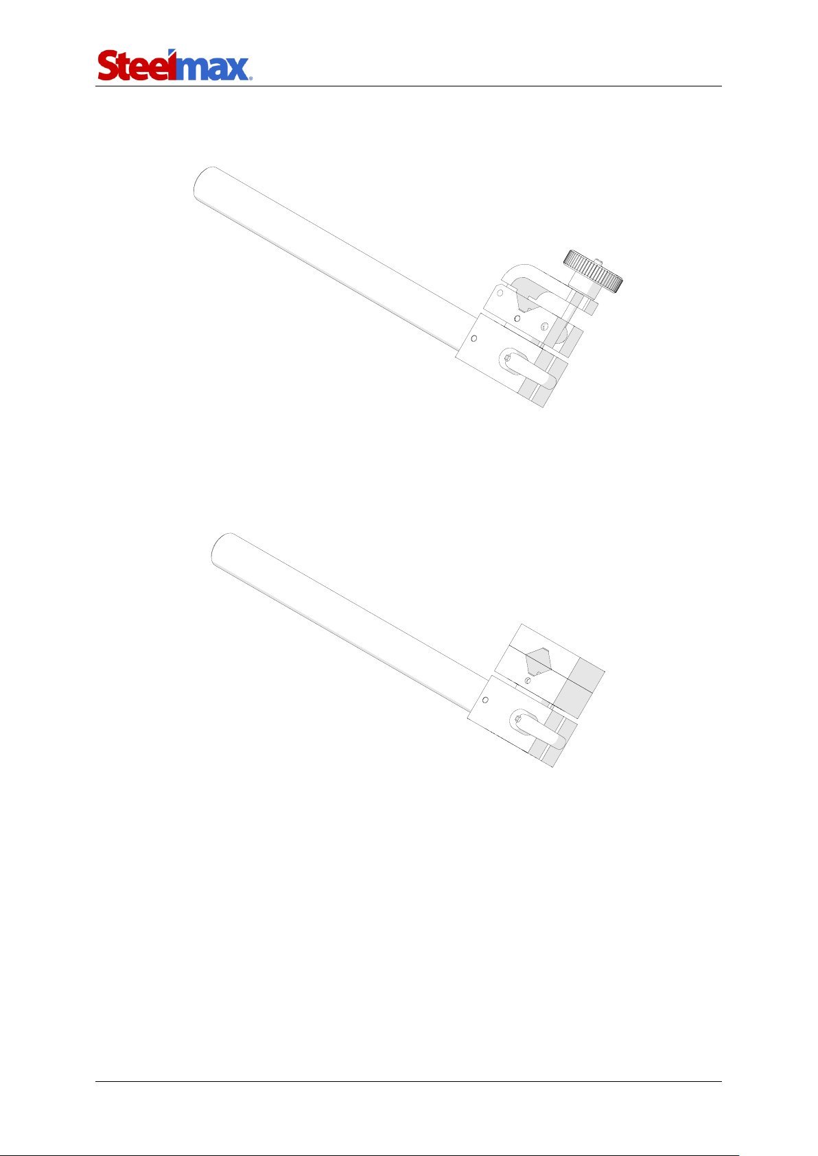
5.4.4. Long rod torch holder with clamp
Allows using a torch with the handle diameter of 16–22 mm (0.63–0.87’’).
5.4.5. Long rod torch holder with clip
Allows using a torch with the handle diameter of 16–22 mm (0.63–0.87’’). Use the
4 mm hex wrench to tighten the torch in the clip.
Part number:
UCW-0466-22-00-00-0
Part number:
UCW-0466-04-00-00-0
Page 29
ARC Runner
ARC Runner Operator’s Manual
29
M5x16
M5x10
Part number:
PRD-0466-43-00-00-0
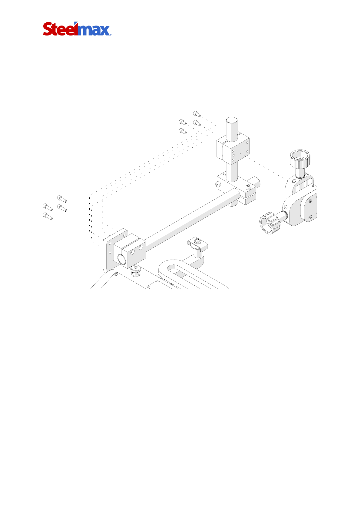
5.5. Torch extension arm
Extends the reach of the torch. Use the 4 mm hex wrench to unscrew the M5x10
screws fixing the cross slide. Next, use the same screws to fix the cross slide at the
end of the arm as shown in the figure. Then, use M5x16 screws to fix the arm to the
carriage.
Page 30
ARC Runner
ARC Runner Operator’s Manual
30
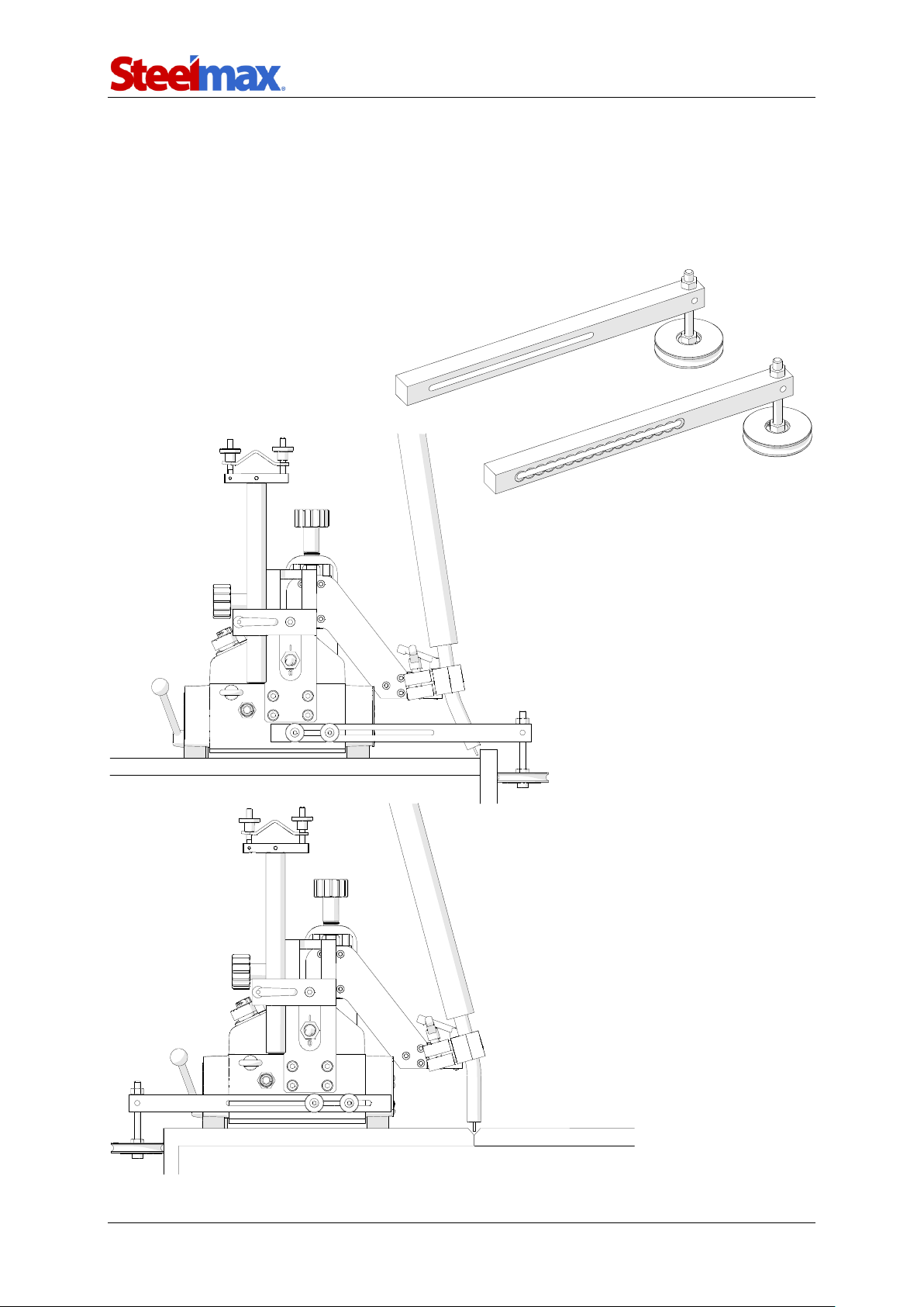
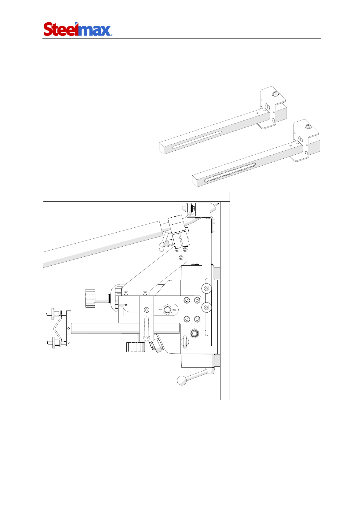
5.6. Guide arms
5.6.1. Edge following guide arms
Allow guiding the carriage along outside edges. Use the 4 mm hex wrench to unscrew
the standard guide arms and install the new guide arms.
Part number (2 units):
PRW-0476-21-00-00-1
Page 31
ARC Runner
ARC Runner Operator’s Manual
31
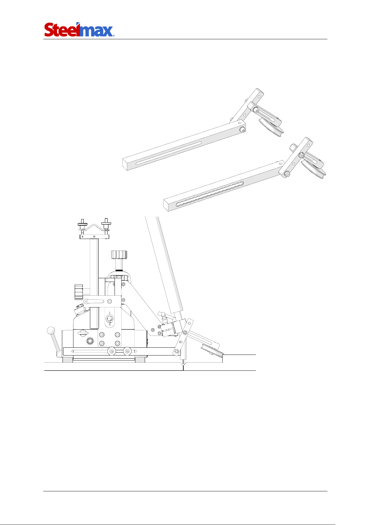
5.6.2. Adjustable guide arms
Allow guiding the carriage along lap joints and templates. Use the 4 mm hex wrench
to unscrew the standard guide arms and install the new guide arms.
Part number (2 units):
PRW-0476-22-00-00-1
Page 32
ARC Runner
ARC Runner Operator’s Manual
32
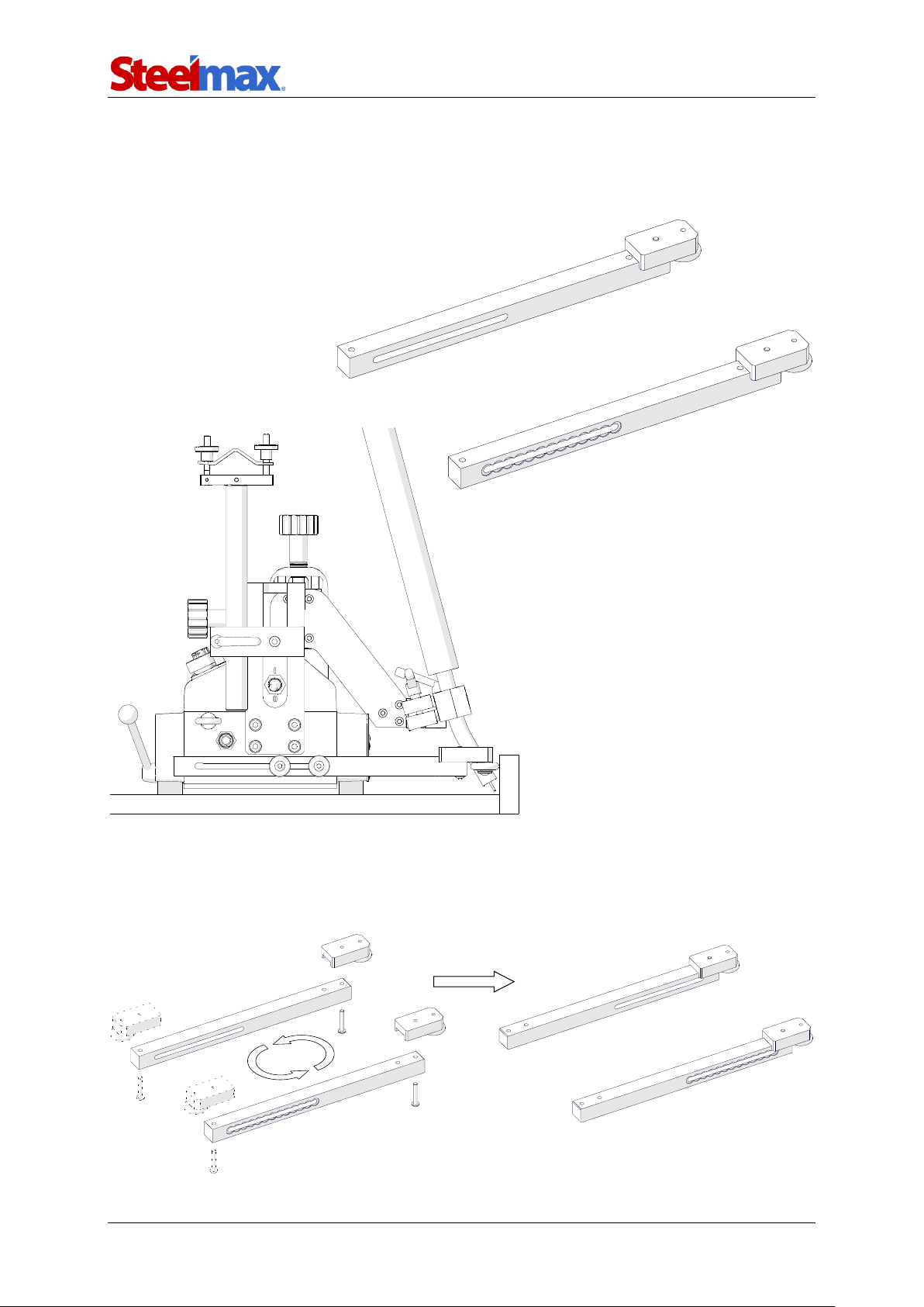
5.6.3. Magnet guide arms
Allow guiding the carriage on ceilings. Use the 4 mm hex wrench to unscrew the
standard guide arms and install the new guide arms.
Part number (2 units):
PRW-0476-52-00-00-1
Page 33
ARC Runner
ARC Runner Operator’s Manual
33
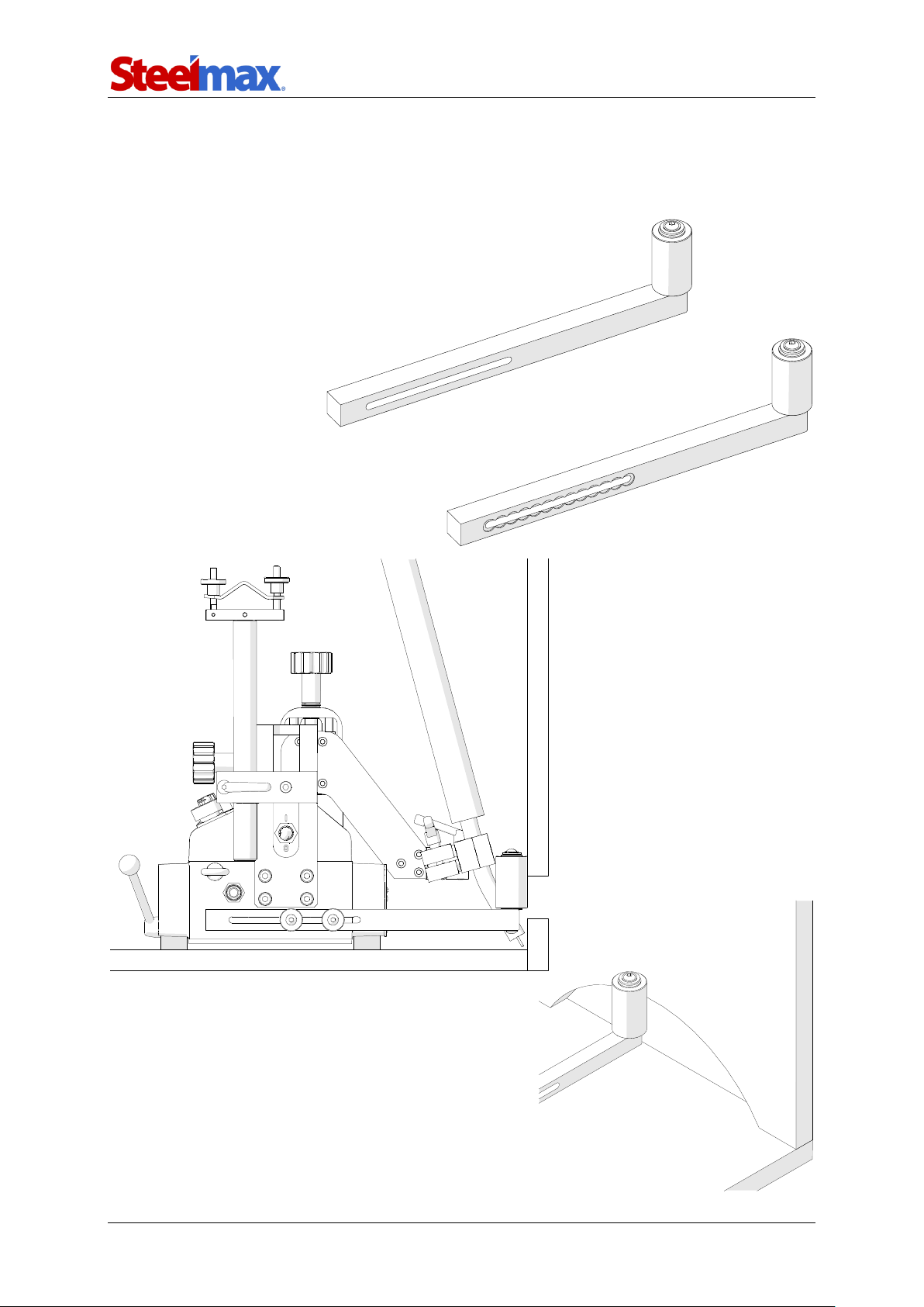
5.6.4. Low guide arms
Allow guiding the carriage along low walls. Use the 4 mm hex wrench to unscrew the
standard guide arms and install the new guide arms.
To position the carriage closer to the workpiece, use the 3 mm hex wrench to
unscrew the roller assemblies. Next, install them at the other end of the guide arms,
and then swap the guide arms.
Part number (2 units):
PRW-0476-54-00-00-1
Page 34
ARC Runner
ARC Runner Operator’s Manual
34
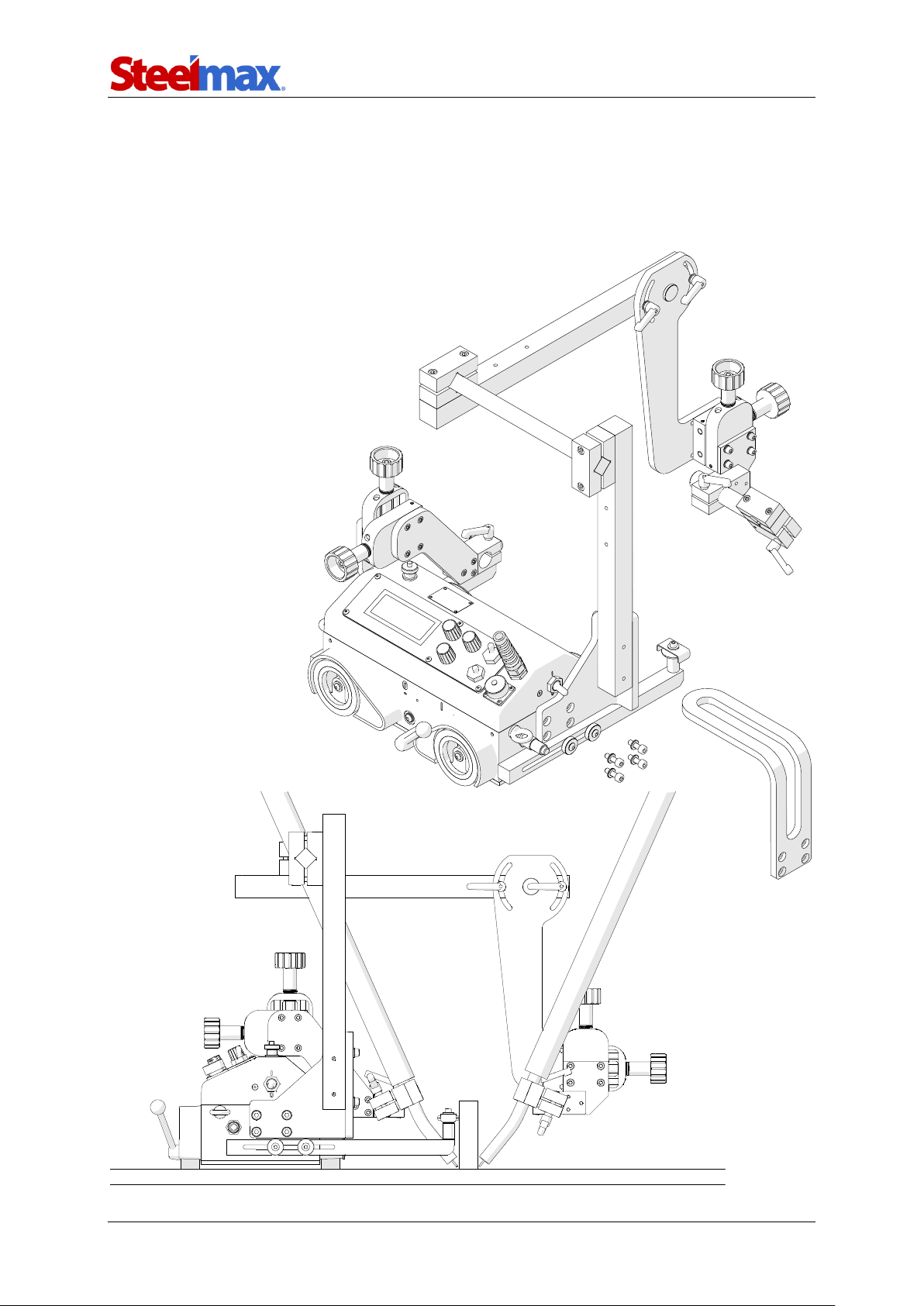
5.6.5. High guide arms
Allow guiding the carriage along walls with holes. Use the 4 mm hex wrench to
unscrew the standard guide arms and install the new guide arms.
Part number (2 units):
PRW-0476-55-00-00-1
Page 35
ARC Runner
ARC Runner Operator’s Manual
35
5.7. Dual torch mount
Allows using a second torch. Use the 5 mm hex wrench to unscrew the M6x20 screws
and washers fixing the carrying handle. Next, use the same screws and washers to
fix the mount to the carriage.
Part number:
PDT-0466-40-00-00-1
Page 36
ARC Runner
ARC Runner Operator’s Manual
36
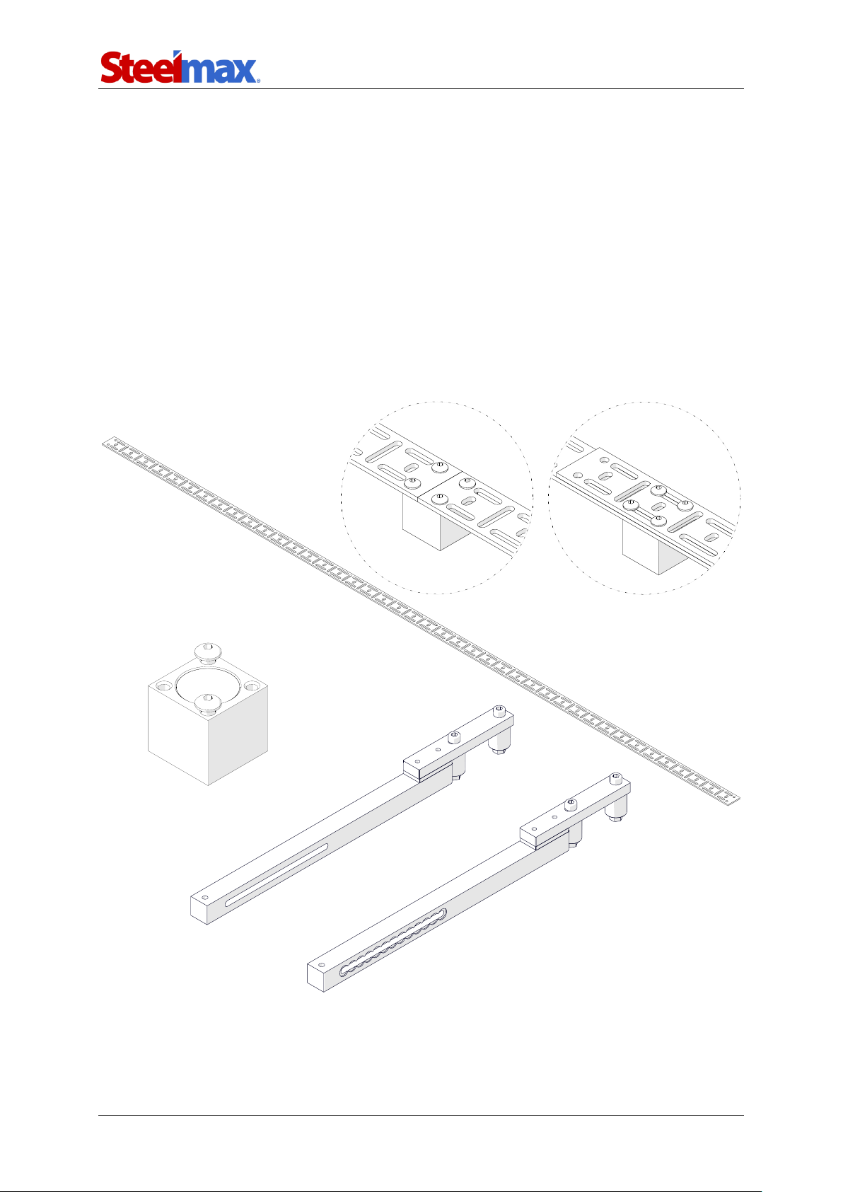
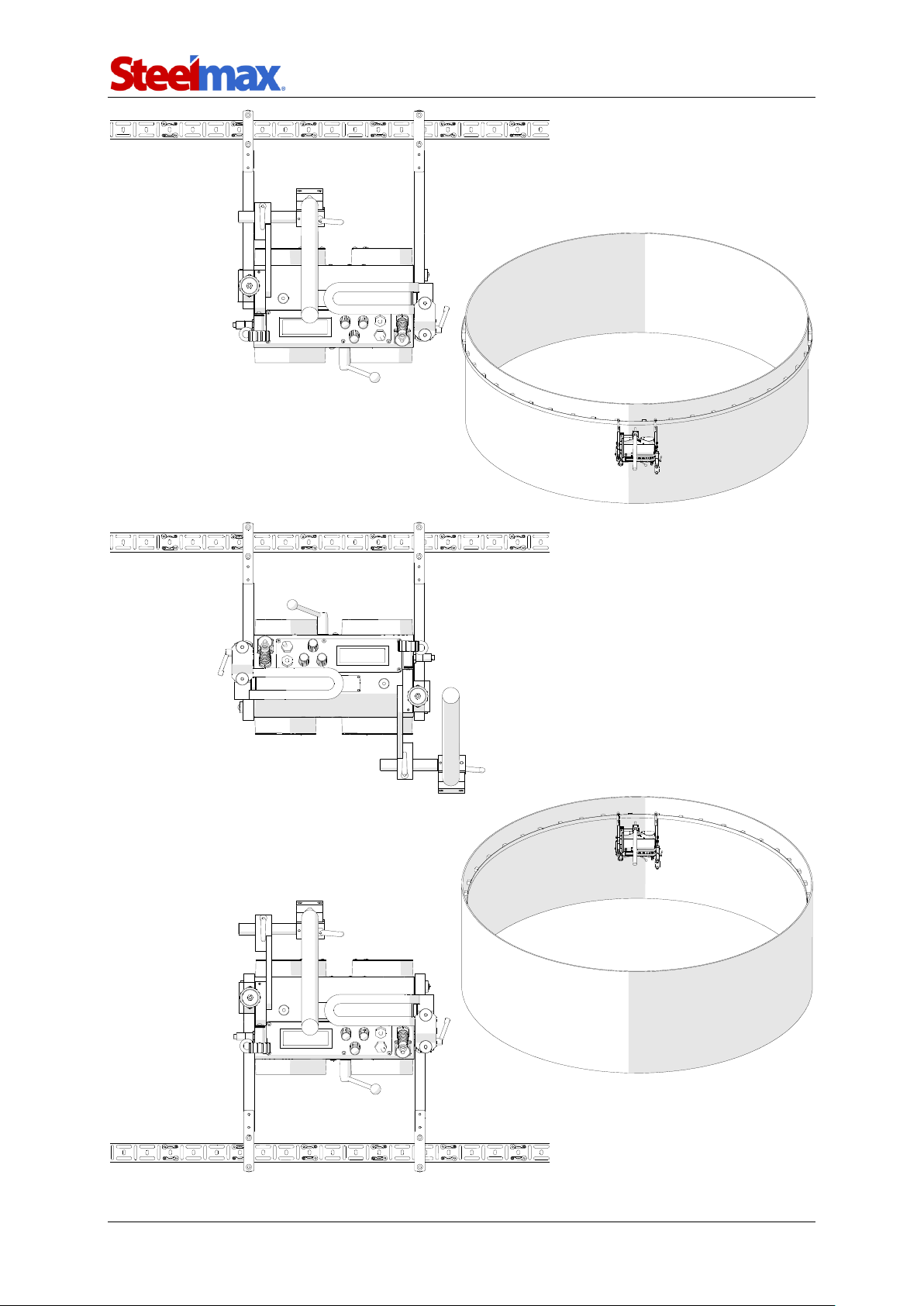
5.8. Flexible guide set
Allows guiding the carriage on planes along a straight line, and on pipes and tanks.
A single flexible guide is 1.85 m (6 ft) long, and its minimum curve radius is 1 m (3.3 ft).
The holding force of a magnet block placed on a 5 mm (0.2’’) thick ferromagnetic
surface is 90 N (20 lbs) up to a temperature of 100°C (212°F). At 180°C (356°F) the
force decreases to 54 N (12 lbs).
Connect two guides with the 3 mm hex wrench and M5x16 screws to form a butt
or lap joint. Next, use the 4 mm hex wrench to remove the standard guide arms and
install the new guide arms.
Flexible guide (1 unit):
PRW-0466-50-01-01-0
Magnet block set:
BLO-0466-68-00-00-0
(includes: 10 magnet blocks
and 22 screws M5x16)
Butt joint
Lap joint
Guide arms (2 units):
PRW-0476-50-01-00-1
Page 37
ARC Runner
ARC Runner Operator’s Manual
37
Page 38
ARC Runner
ARC Runner Operator’s Manual
38
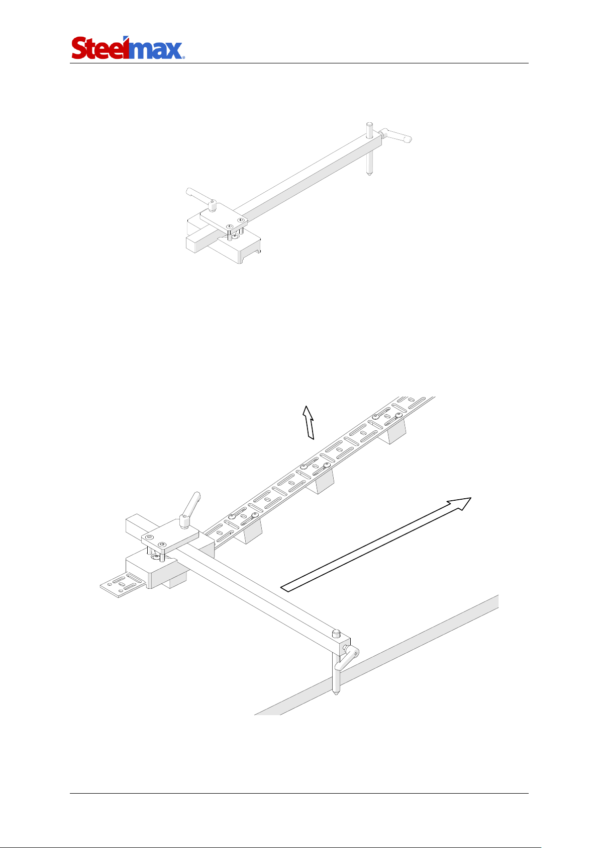
5.9. Guide adjustment tool
Allows the guide to be positioned parallel to an outside edge or a groove.
Fix the magnets to the guide, and position the guide on the workpiece along the
direction of welding. Loosen the levers and put the tool onto the first magnet, resting
the side of the pilot pin on an outside edge or placing the tip of the pilot pin in a
groove. Then, lock the levers in this position and pull the further part of the guide
off the workpiece (1). Next, start moving the tool along the guide (2) to clamp the
successive magnets to the workpiece.
Part number:
UST-0466-53-00-00-0
1
2
Page 39
ARC Runner
ARC Runner Operator’s Manual
39
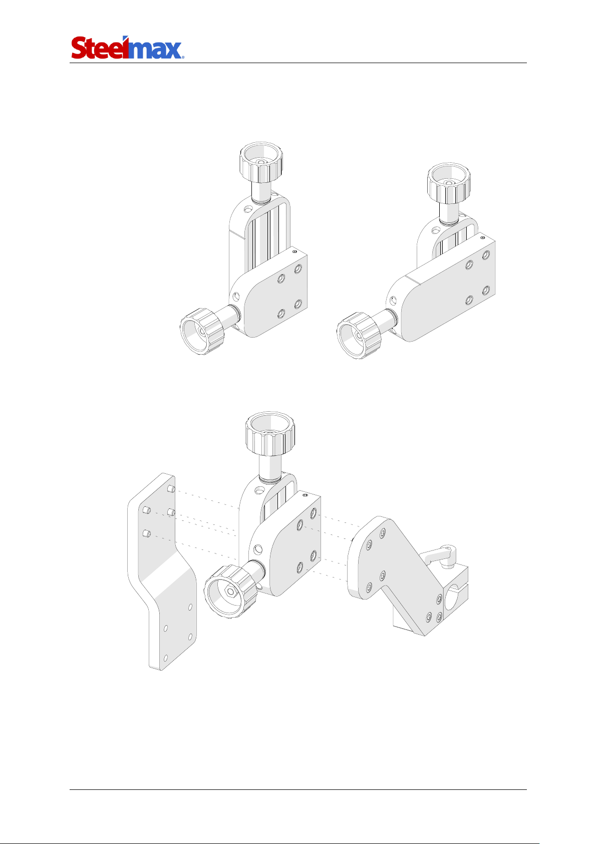
5.10. 76 mm cross slide
Extends either up-down or left-right adjustment range from 0–35 mm (0–1.38’’) to
0–76 mm (0–3’’).
Use the 4 mm hex wrench to remove the standard cross slide and install the new
cross slide.
Part number:
ZSP-0466-46-00-00-1
Page 40
ARC Runner
ARC Runner Operator’s Manual
40
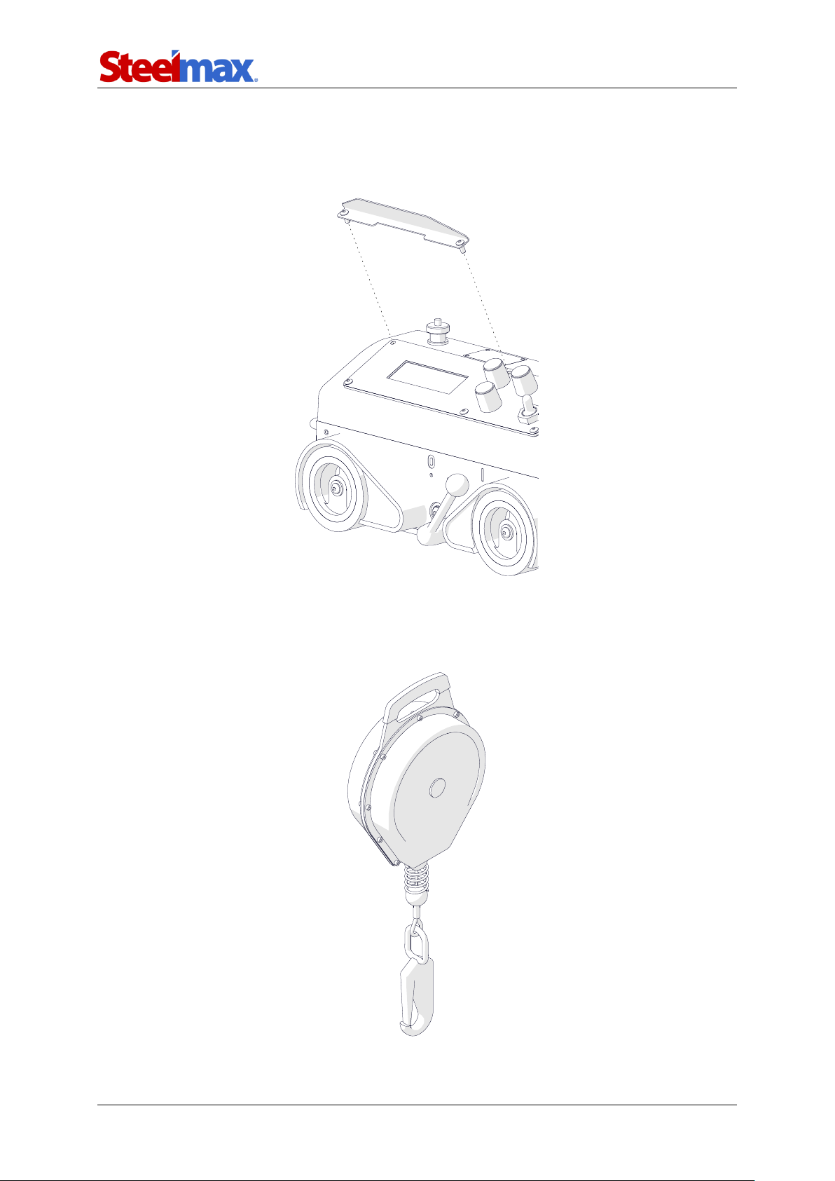
5.11. Display protection shield
Protects the display from dirt. Use the 2.5 mm hex wrench to unscrew the top screws
of the panel, and use them to tighten the shield.
5.12. Fall arrester
Protects the carriage from falling. The length of the line is 10 m (33 ft).
Part number:
OSL-0476-23-00-00-0
Part number:
URZ-000001
Page 41
ARC Runner
ARC Runner Operator’s Manual
41
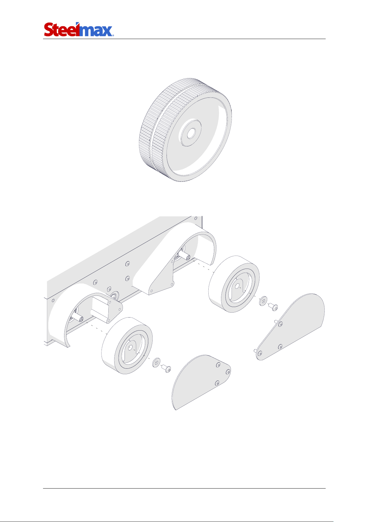
5.13. Stainless steel wheels
Allow working in horizontal position on a preheated plate.
As shown in the figure, use the 2.5 mm hex wrench to remove the cover and use the
3 mm hex wrench to remove four wheels. Install in reverse order.
Part number (1 unit):
KOL-0476-57-00-00-0
Page 42
ARC Runner
ARC Runner Operator’s Manual
42
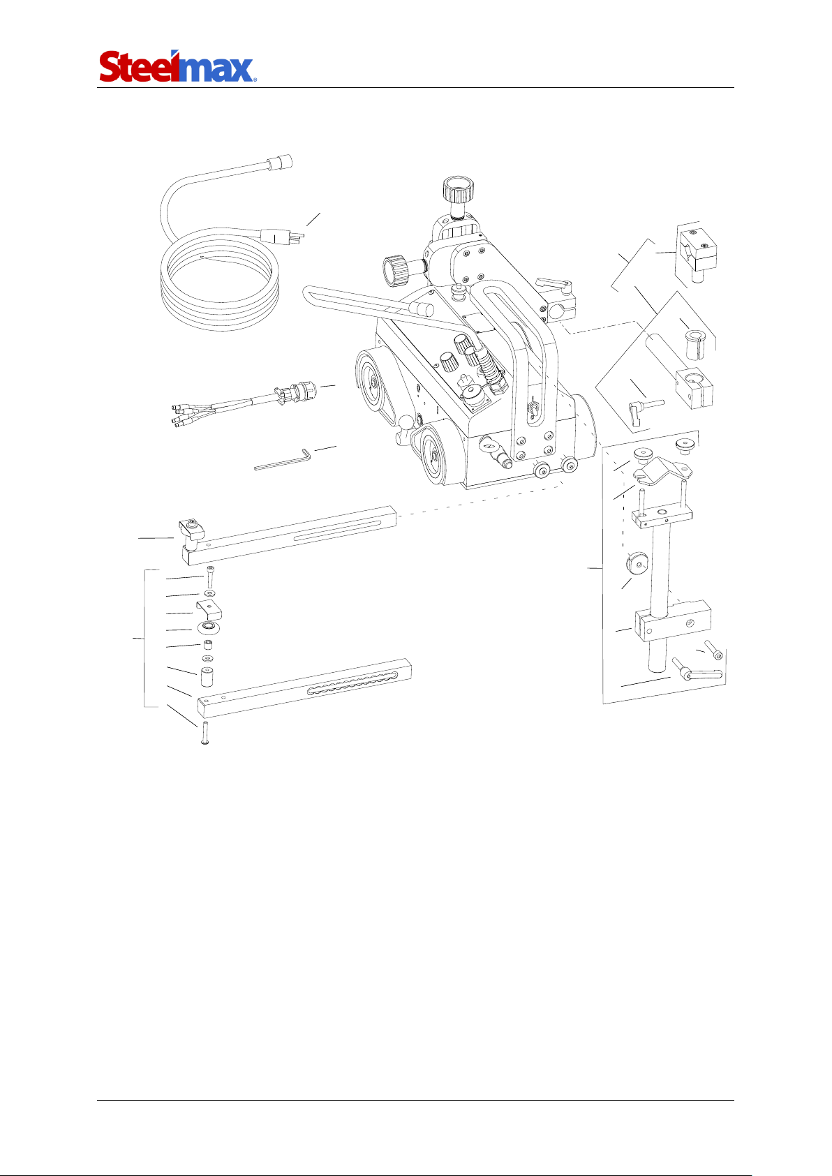
6. 115–230 V EXPLODED VIEWS AND PARTS LIST
4
3
12
5
11
13
14
6
24
21
2
22
25
8
20
19
18
17
16
23
15
10
7
9
1
4
3
12
5
11
13
14
6
24
21
2
22
25
8
20
19
18
17
16
23
15
10
7
9
1
Page 43

ARC Runner
ARC Runner Operator’s Manual
43
ITEM
PART NUMBER
DESCRIPTION
Q-TY
1
KBL-0466-17-00-00-0
START-STOP ARC IGNITION CABLE 6.5 M (20 FT)
1 2 PWD-0466-18-00-00-0
POWER CORD 230V (CEE)
1 2 PWD-0466-21-00-00-0
POWER CORD 230V (AU)
1 2 PWD-0466-23-00-00-0
POWER CORD 120V (UK type G)
1 2 PWD-0466-16-00-00-0
POWER CORD 120V (USA)
1 2 PWD-0466-24-00-00-0
POWER CORD 3x1.5 – WITHOUT PLUG
1
3
PRW-0476-04-00-02-0
LEFT GUIDE ARM ASSY
1
4
PDT-0466-55-00-00-0
CABLE ANCHOR ASSY
1 5 UCW-0476-27-00-00-0
SHORT ROD TORCH HOLDER WITH CLIP ASSY
1 6 KLC-000007
4 MM HEX WRENCH
1 7 TRM-0219-06-16-00-0
CLAMP PLATE I
1
8
KST-0466-55-01-00-0
ANCHOR CLAMPING BLOCK
1
9
NKR-000121
KNURLED NUT M6
2
10
RKJ-000036
HANDLEVER M6-32
1
11
ZCS-0476-06-01-00-0
TORCH CLIP ASSY
1
12
WLK-0476-20-01-00-0
SHORT ROD ASSY
1
13
TLJ-0419-04-02-03-0
INSULATION SLEEVE
1
14
RKJ-000036
HANDLEVER M6-32
1
15
SRB-000177
HEX SOCKET HEAD CAP SCREW M5x22
2
16
PDK-000036
ROUND WASHER 5.5
4
17
OSL-0466-06-02-00-0
ROLLER COVER
2
18
RLK-0221-01-19-00-0
GUIDE ARM ROLLER
2
19
TLJ-0419-06-03-00-0
ROLLER SLEEVE
2
20
TLJ-0476-04-02-00-0
GUIDE ARM SLEEVE
2
21
RAM-0476-04-01-00-2
GUIDE ARM
2
22
WKR-000473
HEX SOCKET BUTTON HEAD SCREW M5x30
2
23
SRB-000123
HEX SOCKET HEAD CAP SCREW M6x35
1
24
NKR-0466-55-02-00-0
ANCHOR NUT
1
25
PRW-0476-04-00-01-0
RIGHT GUIDE ARM ASSY
1
Page 44
ARC Runner
ARC Runner Operator’s Manual
44
13
17
91
40
7
3
43
26
57
14
53
51
75
58
68
73
39
21
66
76
86
83
81
8
9
89
77
44
82
30
32
73
24
59
35
64
22
61
20
10
38
56
34
27
50
48
1
16
20
55
54
31
12
60
11
47
72
19
45
46
23
29
36
80
78
88
33
41
79
42
85
87
84
49
25
63
18
28
37
4
5
52
62
74
6
2
68
67
69
71
70
92
Page 45

ARC Runner
ARC Runner Operator’s Manual
45
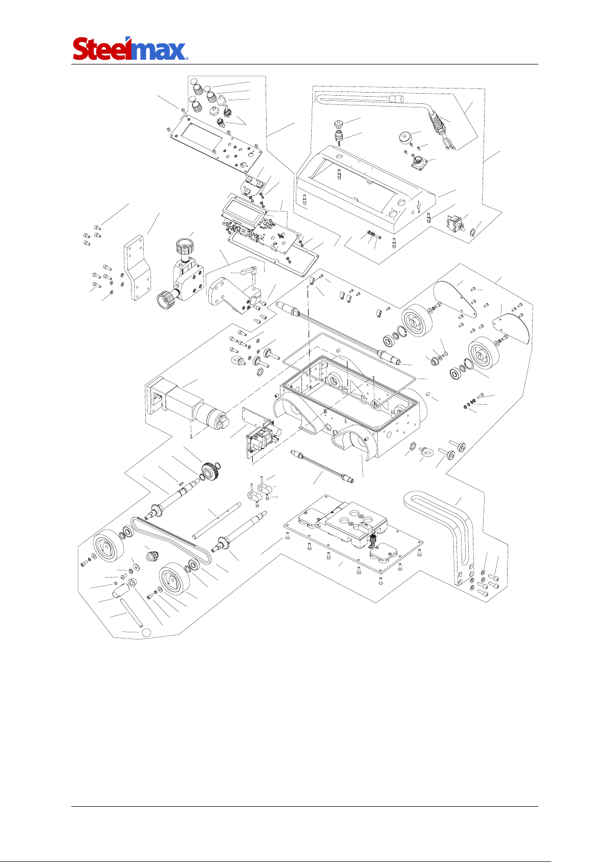
ITEM
PART NUMBER
DESCRIPTION
Q-TY
1
ZSP-0466-03-00-00-1
CROSS SLIDE ASSY
1
2
KUL-0466-13-00-00-0
LEVER BALL
1
3
ZSP-0476-01-00-00-0
DRIVE SYSTEM
1
4
GLK-0476-01-11-00-0
LEVER HOLDER
1
5
DZW-0476-01-12-00-0
LEVER
1
6
RKJ-0476-01-13-00-0
CARRYING HANDLE
1
7
PKR-0476-02-00-00-0
CONTROLLER HOUSING ASSY
1
8
PNL-0476-02-20-00-0
CONTROL PANEL ASSY
1
9
PLY-0476-03-00-00-0
TORCH HOLDER PLATE
1
10
WSP-0476-05-00-00-1
SLIDE BRACKET
1
11
SRB-0476-08-00-00-0
GUIDE ARM SCREW
4
12
USZ-0476-09-00-00-0
SEAL
1
13
PDK-000017
ROUND WASHER 5.3
4
14
PDK-000021
ROUND WASHER 6.4
4
16
WKR-000066
HEX SOCKET SET SCREW WITH CONE POINT M6x10
4
17
WKR-000092
HEX SOCKET BUTTON HEAD SCREW M4x10
6
18
WKR-000057
HEX SOCKET SET SCREW WITH FLAT POINT M6x6
1
19
SRB-000278
EYE BOLT M6
2
20
SRB-000075
HEX SOCKET HEAD CAP SCREW M5x10
8
21
SRB-000114
HEX SOCKET HEAD CAP SCREW M6x20
4
22
SRB-000083
HEX SOCKET HEAD CAP SCREW M5x16
4
23
WPS-0170-00-22-00-1
KEY 3x5x13
1
24
KRZ-0233-01-16-00-0
CAM
2
25
PDK-0233-01-21-00-0
DISTANCE WASHER 12.1x19x3
4
26
PDK-0233-01-23-00-0
WASHER 6.4x12x1.6
1
27
TLJ-0233-01-27-00-0
SLEEVE BEARING 9x16x10
1
28
TLJ-0233-01-28-00-0
SLEEVE BEARING 12x16x10
1
29
ZSP-0476-01-16-00-0
LIMIT SWITCH ASSY
1
30
KOL-0466-01-08-00-0
BEVEL GEAR z30
1
31
KRP-0476-01-01-00-1
BODY
1
32
WLK-0476-01-02-00-0
FRONT DRIVE SHAFT ASSY
1
33
WLK-0476-01-03-00-0
BACK DRIVE SHAFT ASSY
1
34
BLO-0476-01-04-00-0
MAGNET BLOCK ASSY
1
35
NPN-0476-01-05-00-0
CHAIN TENSIONER
1
36
RDK-0476-01-06-00-0
GEARBOX ASSY
1
37
KOL-0476-01-07-00-0
DRIVE WHEEL
4
38
OSL-0476-01-08-00-0
WHEEL GUARD RIGHT
1
39
OSL-0476-01-09-00-0
WHEEL GUARD LEFT
1
40
OSK-0476-01-10-00-0
SHAFT
1
41
LNC-0476-01-14-00-0
ROLLER CHAIN
1
42
ZSL-0476-01-15-00-0
POWER SUPPLY ASSY
1
43
NKR-000013
HEX NUT M4
2
44
NKR-000115
NUT M16x1.5
2
45
PRS-000005
EXTERNAL RETAINING RING 15z
2
46
KLK-000013
SPRING DOWEL PIN 4x16
2
47
OBJ-000002
HOLDER FOR FIXING LEADS 4
4
48
PRS-000018
INTERNAL RETAINING RING 28w
2
49
LOZ-000038
BALL BEARING 12x28x8
4
Page 46

ARC Runner
ARC Runner Operator’s Manual
46
ITEM
PART NUMBER
DESCRIPTION
Q-TY
50
PDK-000017
ROUND WASHER 5.3
4
51
PDK-000021
ROUND WASHER 6.4
1
52
PDK-000036
ROUND WASHER 5.5
4
53
PDK-000037
ROUND WASHER 6.5
1
54
PDK-000060
EXTERNAL TOOTH LOCK WASHER 4.3
2
55
WKR-000152
CROSS RECESSED COUNTERSUNK HEAD SCREW M4x16
1
56
WKR-000136
HEX SOCKET COUNTERSUNK HEAD SCREW M5x16
18
57
WKR-000097
HEX SOCKET COUNTERSUNK HEAD SCREW M5x12
1
58
SRB-000083
HEX SOCKET HEAD CAP SCREW M5x16
4
59
SRB-000061
HEX SOCKET HEAD CAP SCREW M4x10
2
60
WKR-000091
HEX SOCKET BUTTON HEAD SCREW M4x8
4
61
WKR-000092
HEX SOCKET BUTTON HEAD SCREW M4x10
10
62
SRB-000078
HEX SOCKET HEAD CAP SCREW M5x12
4
63
WKR-000290
HEX SOCKET BUTTON HEAD SCREW M6x12
1
64
USZ-0476-02-02-01-0
PANEL PLATE SEAL
1
65
MSK-0476-02-20-10-0
PANEL PLATE ASSY
1
66
MDL-0476-02-02-21-2
ELECTRONIC CONTROLLER ASSY
1
67
MDL-0476-02-02-30-1
ENCODER MODULE
1
68
PDK-000058
EXTERNAL TOOTH LOCK WASHER 3.2
7
69
WZK-0476-02-02-02-0
TRAVEL DIRECTION AND ARC IGNITION WIRE SET
1
70
OSL-000036
LEVER SWITCH COVER
2
71
PKT-000016
POTENTIOMETER KNOB
3
72*
WZK-0476-02-07-00-0
POWER SWITCH WIRE SET
1
73
WKR-000181
CROSS RECESSED PAN HEAD SCREW M3x6
7
74
MDL-0476-02-02-22-2
DISPLAY MODULE
1
75
WZK-0466-02-09-00-0
POWER WIRE SET
1
76
PKR-0476-02-01-00-1
CONTROLLER HOUSING
1
77
DLW-000007
CABLE GLAND WITH STRAIN RELIEF PG11
1
78
SZP-0476-02-03-00-0
PIN
4
79
WZK-0476-02-04-00-0
ARC IGNITION SOCKET WIRE SET
1
80
WZK-0476-02-06-00-0
OSCILLATION SOCKET WIRE SET
1
81
NKR-000013
HEX NUT M4
1
82
NKR-000120
SOCKET CAP
1
83
PDK-000060
EXTERNAL TOOTH LOCK WASHER 4.3
2
84
PDK-000165
LOCK WASHER 12/19
1
85
PNK-000026
LEVER SWITCH 641H/3
1
86
WKR-000435
HEX SOCKET COUNTERSUNK HEAD SCREW M4x16
1
87
WKR-000287
HEX SOCKET BUTTON HEAD SCREW M3x10
4
88
ZLP-000025
PLUG M12
1
89
RKJ-000036
HANDLEVER M6-32
1
90*
PWD-0476-10-00-00-0
GROUNDING WIRE
1
91
PDK-000045
SPRING WASHER 5.1
4
92
ZLP-000007
CAP
3
* not shown in the drawing
Page 47
ARC Runner
ARC Runner Operator’s Manual
47
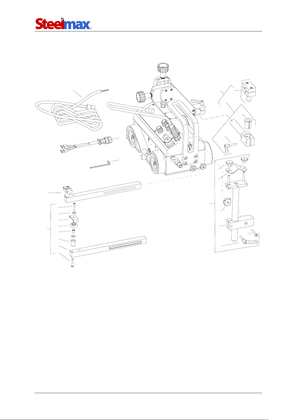
7. 42 V EXPLODED VIEWS AND PARTS LIST
2
4
3
12
5
11
13
14
6
24
21
22
25
8
20
19
18
17
16
23
15
10
7
9
1
Page 48

ARC Runner
ARC Runner Operator’s Manual
48
ITEM
PART NUMBER
DESCRIPTION
Q-TY
1
KBL-0466-17-00-00-0
START-STOP ARC IGNITION CABLE 6.5 M (20 FT)
1
2
PWD-0621-03-00-00-0
POWER CORD 42V
1
3
PRW-0476-04-00-02-0
LEFT GUIDE ARM ASSY
1
4
PDT-0466-55-00-00-0
CABLE ANCHOR ASSY
1
5
UCW-0476-27-00-00-0
SHORT ROD TORCH HOLDER WITH CLIP ASSY
1
6
KLC-000007
4 MM HEX WRENCH
1
7
TRM-0219-06-16-00-0
CLAMP PLATE I
1
8
KST-0466-55-01-00-0
ANCHOR CLAMPING BLOCK
1
9
NKR-000121
KNURLED NUT M6
2
10
RKJ-000036
HANDLEVER M6-32
1
11
ZCS-0476-06-01-00-0
TORCH CLIP ASSY
1
12
WLK-0476-20-01-00-0
SHORT ROD ASSY
1
13
TLJ-0419-04-02-03-0
INSULATION SLEEVE
1
14
RKJ-000036
HANDLEVER M6-32
1
15
SRB-000177
HEX SOCKET HEAD CAP SCREW M5x22
2
16
PDK-000036
ROUND WASHER 5.5
4
17
OSL-0466-06-02-00-0
ROLLER COVER
2
18
RLK-0221-01-19-00-0
GUIDE ARM ROLLER
2
19
TLJ-0419-06-03-00-0
ROLLER SLEEVE
2
20
TLJ-0476-04-02-00-0
GUIDE ARM SLEEVE
2
21
RAM-0476-04-01-00-2
GUIDE ARM
2
22
WKR-000473
HEX SOCKET BUTTON HEAD SCREW M5x30
2
23
SRB-000123
HEX SOCKET HEAD CAP SCREW M6x35
1
24
NKR-0466-55-02-00-0
ANCHOR NUT
1
25
PRW-0476-04-00-01-0
RIGHT GUIDE ARM ASSY
1
Page 49
ARC Runner
ARC Runner Operator’s Manual
49
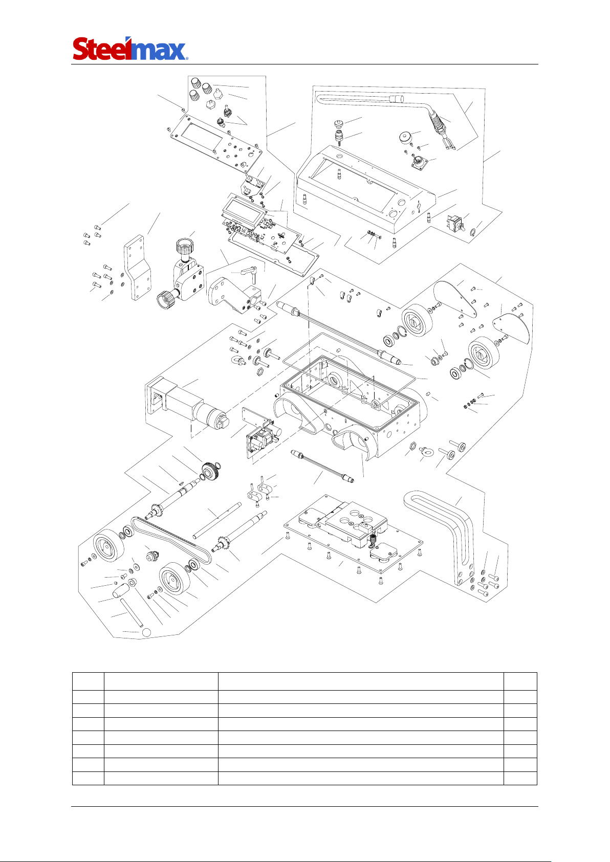
13
17
91
40
7
3
43
26
57
14
53
51
75
58
68
73
39
21
66
76
86
83
81
8
9
89
77
44
82
30
32
73
24
59
35
64
22
61
20
10
38
56
34
27
50
48
1
16
20
55
54
31
12
60
11
47
72
19
45
46
23
29
36
80
78
88
33
41
79
42
85
87
84
49
25
63
18
28
37
4
5
52
62
74
6
2
68
67
69
71
70
ITEM
PART NUMBER
DESCRIPTION
Q-TY
1
ZSP-0466-03-00-00-1
CROSS SLIDE ASSY
1
2
KUL-0466-13-00-00-0
LEVER BALL
1 3 ZSP-0623-01-00-00-0
DRIVE SYSTEM 42V
1 4 GLK-0476-01-11-00-0
LEVER HOLDER
1 5 DZW-0476-01-12-00-0
LEVER
1 6 RKJ-0476-01-13-00-0
CARRYING HANDLE
1 7 PKR-0623-02-00-00-0
CONTROLLER HOUSING ASSY 42V
1
Page 50

ARC Runner
ARC Runner Operator’s Manual
50
ITEM
PART NUMBER
DESCRIPTION
Q-TY
8
PNL-0476-02-20-00-0
CONTROL PANEL ASSY
1
9
PLY-0476-03-00-00-0
TORCH HOLDER PLATE
1
10
WSP-0476-05-00-00-1
SLIDE BRACKET
1
11
SRB-0476-08-00-00-0
GUIDE ARM SCREW
4
12
USZ-0476-09-00-00-0
SEAL
1
13
PDK-000017
ROUND WASHER 5.3
4
14
PDK-000021
ROUND WASHER 6.4
4
16
WKR-000066
HEX SOCKET SET SCREW WITH CONE POINT M6x10
4
17
WKR-000092
HEX SOCKET BUTTON HEAD SCREW M4x10
6
18
WKR-000057
HEX SOCKET SET SCREW WITH FLAT POINT M6x6
1
19
SRB-000278
EYE BOLT M6
2
20
SRB-000075
HEX SOCKET HEAD CAP SCREW M5x10
8
21
SRB-000114
HEX SOCKET HEAD CAP SCREW M6x20
4
22
SRB-000083
HEX SOCKET HEAD CAP SCREW M5x16
4
23
WPS-0170-00-22-00-1
KEY 3x5x13
1
24
KRZ-0233-01-16-00-0
CAM 2 25
PDK-0233-01-21-00-0
DISTANCE WASHER 12.1x19x3
4
26
PDK-0233-01-23-00-0
WASHER 6.4x12x1.6
1
27
TLJ-0233-01-27-00-0
SLEEVE BEARING 9x16x10
1
28
TLJ-0233-01-28-00-0
SLEEVE BEARING 12x16x10
1
29
ZSP-0476-01-16-00-0
LIMIT SWITCH ASSY
1
30
KOL-0466-01-08-00-0
BEVEL GEAR z30
1
31
KRP-0476-01-01-00-1
BODY
1
32
WLK-0476-01-02-00-0
FRONT DRIVE SHAFT ASSY
1
33
WLK-0476-01-03-00-0
BACK DRIVE SHAFT ASSY
1
34
BLO-0476-01-04-00-0
MAGNET BLOCK ASSY
1
35
NPN-0476-01-05-00-0
CHAIN TENSIONER
1
36
RDK-0476-01-06-00-0
GEARBOX ASSY
1
37
KOL-0476-01-07-00-0
DRIVE WHEEL
4
38
OSL-0476-01-08-00-0
WHEEL GUARD RIGHT
1
39
OSL-0476-01-09-00-0
WHEEL GUARD LEFT
1
40
OSK-0476-01-10-00-0
SHAFT
1
41
LNC-0476-01-14-00-0
ROLLER CHAIN
1
42
ZSL-0623-01-01-00-0
POWER SUPPLY ASSY 42V
1
43
NKR-000013
HEX NUT M4
2
44
NKR-000115
NUT M16x1.5
2
45
PRS-000005
EXTERNAL RETAINING RING 15z
2
46
KLK-000013
SPRING DOWEL PIN 4x16
2
47
OBJ-000002
HOLDER FOR FIXING LEADS 4
4
48
PRS-000018
INTERNAL RETAINING RING 28w
2
49
LOZ-000038
BALL BEARING 12x28x8
4
50
PDK-000017
ROUND WASHER 5.3
4
51
PDK-000021
ROUND WASHER 6.4
1
52
PDK-000036
ROUND WASHER 5.5
4
53
PDK-000037
ROUND WASHER 6.5
1
54
PDK-000060
EXTERNAL TOOTH LOCK WASHER 4.3
2
55
WKR-000152
CROSS RECESSED COUNTERSUNK HEAD SCREW M4x16
1
56
WKR-000136
HEX SOCKET COUNTERSUNK HEAD SCREW M5x16
18
57
WKR-000097
HEX SOCKET COUNTERSUNK HEAD SCREW M5x12
1
58
SRB-000083
HEX SOCKET HEAD CAP SCREW M5x16
4
59
SRB-000061
HEX SOCKET HEAD CAP SCREW M4x10
2
Page 51

ARC Runner
ARC Runner Operator’s Manual
51
ITEM
PART NUMBER
DESCRIPTION
Q-TY
60
WKR-000091
HEX SOCKET BUTTON HEAD SCREW M4x8
4
61
WKR-000092
HEX SOCKET BUTTON HEAD SCREW M4x10
10
62
SRB-000078
HEX SOCKET HEAD CAP SCREW M5x12
4
63
WKR-000290
HEX SOCKET BUTTON HEAD SCREW M6x12
1
64
USZ-0476-02-02-01-0
PANEL PLATE SEAL
1
65
MSK-0476-02-20-10-0
PANEL PLATE ASSY
1
66
MDL-0476-02-02-21-2
ELECTRONIC CONTROLLER ASSY
1
67
MDL-0476-02-02-30-1
ENCODER MODULE
1
68
PDK-000058
EXTERNAL TOOTH LOCK WASHER 3.2
7
69
WZK-0476-02-02-02-0
TRAVEL DIRECTION AND ARC IGNITION WIRE SET
1
70
OSL-000036
LEVER SWITCH COVER
2
71
PKT-000016
POTENTIOMETER KNOB
3
73
WKR-000181
CROSS RECESSED PAN HEAD SCREW M3x6
7
74
MDL-0476-02-02-22-2
DISPLAY MODULE
1
75
WZK-0621-01-02-00-0
POWER WIRE SET 42V
1
76
PKR-0476-02-01-00-1
CONTROLLER HOUSING
1
77
DLW-000007
CABLE GLAND WITH STRAIN RELIEF PG11
1
78
SZP-0476-02-03-00-0
PIN
4
79
WZK-0476-02-04-00-0
ARC IGNITION SOCKET WIRE SET
1
80
WZK-0476-02-06-00-0
OSCILLATION SOCKET WIRE SET
1
81
NKR-000013
HEX NUT M4
1
82
NKR-000120
SOCKET CAP
1
83
PDK-000060
EXTERNAL TOOTH LOCK WASHER 4.3
2
84
PDK-000165
LOCK WASHER 12/19
1
85
PNK-000026
LEVER SWITCH 641H/3
1
86
WKR-000435
HEX SOCKET COUNTERSUNK HEAD SCREW M4x16
1
87
WKR-000287
HEX SOCKET BUTTON HEAD SCREW M3x10
4
88
ZLP-000025
PLUG M12
1
89
RKJ-000036
HANDLEVER M6-32
1
90*
PWD-0476-10-00-00-0
GROUNDING WIRE
1
91
PDK-000045
SPRING WASHER 5.1
4
* not shown in the drawing
Page 52
ARC Runner
ARC Runner Operator’s Manual
52
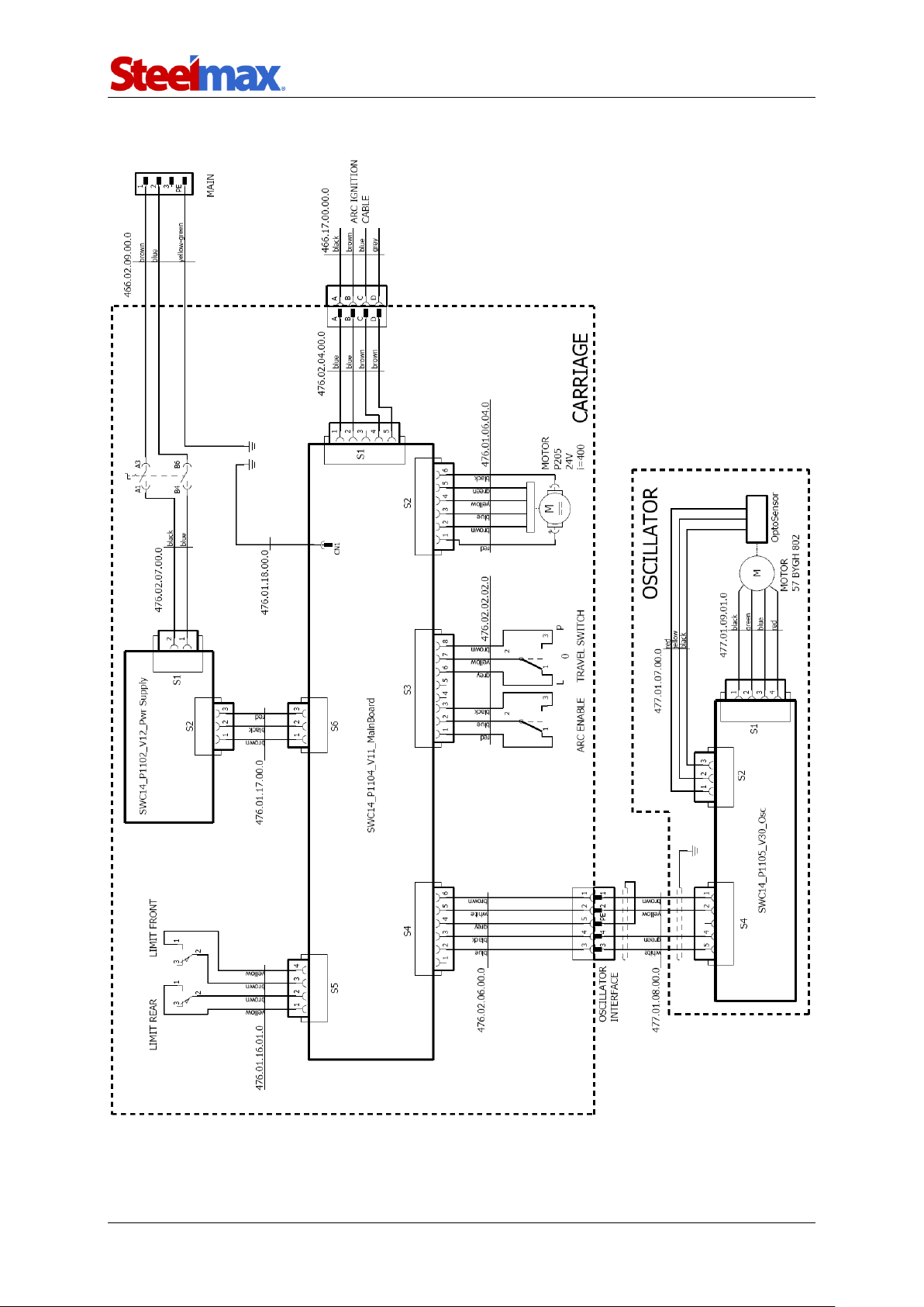
8. 115–230 V WIRING DIAGRAM
Page 53
ARC Runner
ARC Runner Operator’s Manual
53
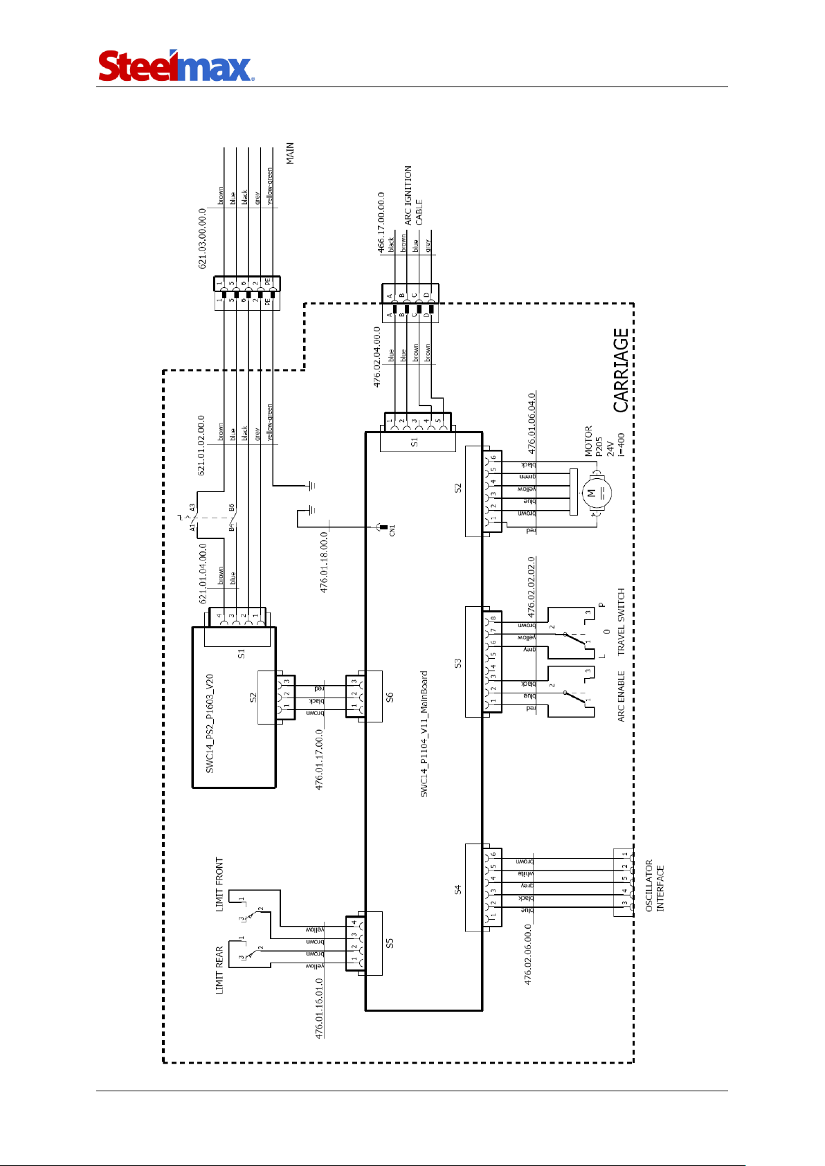
9. 42 V WIRING DIAGRAM
Page 54

ARC Runner
ARC Runner Operator’s Manual
54
10. DECLARATION OF CONFORMITY
EC Declaration of Conformity
We
PROMOTECH sp. z o.o.
ul. Elewatorska 23/1
15-620 Białystok
Poland
declare with full responsibility that:
ARC RUNNER WELDING CARRIAGE
is manufactured in accordance with the following standards:
• EN 12100
• EN 60745-1
• EN 60974-10
and satisfies safety regulations of the guidelines: 2004/108/EC, 2006/95/EC, 2006/42/EC.
Person authorized to compile the technical file:
Marek Siergiej, ul. Elewatorska 23/1, 15-620 Białystok
Białystok, 4 March 2015 ___________________________
Marek Siergiej
CEO
Page 55

ARC Runner
ARC Runner Operator’s Manual
55
11. QUALITY CERTIFICATE
Machine control card
ARC RUNNER WELDING CARRIAGE
□ 115–230 V
□ 42 V
Serial number .....................................................................
Electric test
Type of test
Result
Name of tester
Insulation electrical strength test
(1000 V, 50 Hz)
...................................
Date
Continuity test of the protective earth system
…........ Ω
...................................
Signature
Quality control .................................................
Adjustments, inspections
Quality control .................................................
Page 56

ARC Runner
ARC Runner Operator’s Manual
56
12. WARRANTY CARD
WARRANTY CARD No...........
.......................................................................... in the name of Manufacturer warrants
the ARC Runner Welding Carriage to be free of defects in material and workmanship
under normal use for a period of 12 months from the date of sale.
This warranty does not cover wheels as well as damage or wear that arise from
misuse, accident, tempering or any other causes not related to defects in workmanship
or material.
Date of production .........................................................................................................
Serial number ................................................................................................................
Date of sale ...................................................................................................................
Signature of seller ..........................................................................................................
2.13 / 29 November 2017
WE RESERVE THE RIGHT TO MAKE CHANGES IN THIS MANUAL WITHOUT NOTICE
 Loading...