

Steel-Line ST50EVOB, ST50EVOC Installation And Operating Instructions Manual

www.steel-line.com.au
1800 427 243
ST50EVOB
ST50EVOC
Sectional Garage Door Opener
Installation and Operating Instructions
Owners Copy: SAVE THESE INSTRUCTIONS for future reference
This manual contains IMPORTANT SAFETY information
DO NOT PROCEED WITH THE INSTALLATION BEFORE READING THOROUGHLY

START BY READING THESE IMPORTANT SAFETY INSTRUCTIONS
Failureto complywith the followinginstructions may resultin seriouspersonal injuryor propertydamage.
•
• Read and follow all instructions carefully.
• The garage door opener is designed and tested to offer safe service, provided it is installed and operated in
strict accordance with the instructions in this manual.
hese safety alert symbols mean WARNING : A possible risk to personal safety or property
T
damage exists.
Keep garage door balanced. Do not let the garage door
opener compensate for a binding or sticking garage door.
ticking, binding or unbalanced doors must be repaired
S
before installing this opener.
Do not wear rings, watches or loose clothing while
installing or servicing a garage door opener. Wear gloves,
safety goggles and suitable protective clothing where
appropriate.
Frequently examine the door installation, in particular
cable, springs andmountings for signs of wear, damage or
imbalance. Do not use if repair or adjustment is needed
since springs and hardware are under extreme tension
and a fault can cause serious personal injury.
To avoid serious personal injury from entanglement,
remove all ropes, chains and locks connected to the
garage door before installing the door opener.
Installation and wiring must be in compliance with your
local building and electrical codes.
The safety reverse system test is very important. Your
garage door MUST reverse on contact with a 40 mm high
obstacle placed on the floor. Failure to properly adjust the
opener may result in serious personal injury from a closing
garage door. Repeat the test once a month and make
any necessary adjustments.
This appliance is not intended for use by persons
(including children) with reduced physical, sensory or
mental capabilities, or lack of experience and knowledge,
unless they have been given supervision or instruction
concerning use of the appliance by a person responsible
for their safety.
Use the Manual Release only for the separation of the
carriage from the drive and - if possible - ONLY with the
door closed. Do not use the red handle to push the door
up or pullit down. Operation ofthe emergency releasecan
lead to uncontrolled movements of the door, if springs are
weak or broken or if the door is unbalanced. Mount the
release handle of the emergency release at a height less
than 1.8 m from the floor.
Warning: If your garage has no service entrance door, an E1702M outside quick release must be installed. This
accessory allows manual operation of the garage
CONTENTS PAGE
SAFETY INSTRUCTIONS . .. . . . . . . . .1
BEFORE YOU BEGIN . . . . . . . . . . . . . .2
DOOR TYPES . . . . . . . . . . . . . . . . . . . .2
CARTON INVENTORY . . . . . . . . . . . . .3
RAIL SIZES . . . . . . . . . . . . . . . . . . . . . .3
TOOLS REQUIRED . . . . . . . . . . . . . . . .4
HARDWARE PROVIDED . . . . . . . . . . . .4
COMPLETED INSTALLATION . . . . . . . .4
CONTROL PANEL . . . . . . . . . . . . . . . . .5
ASSEMBLY . . . . . . . . . . . . . . . . . . . . . .6
INSTALLATION . . . . . . . . . . . . . . . . .7-10
OPERATE THE MANUAL RELEASE . .10
ADJUSTMENT . . . . . . . . . . . . . . . . . . .11
TEST SAFETY REVERSE SYSTEM . .12
WARNING!
The optional Protector System
installations where the closing force as measured on the
bottom of the door is over 400 N (40 kgf). Excessive force will
interfere with the proper operation of the Safety Reverse System
or damage the garage door.
SPECIAL NOTE: Steel-line strongly recommends that The
Protector System
After installation, ensure that the parts of the door do not
extend over public footpaths or roads.
Install the wireless wall control (or any additional wall control) in
a location where the garage door is visible, at a height of at
least 1.5 m and out of the reach of children. Do not allow
children to operate push button(s) or transmitter(s). Serious
personal injury from a closing garage door may result from
misuse of the opener.
Permanently fasten theWarning Labels in Prominent Places,
adjacent to Wall Controls and on manual release mechanism as
a reminder of safe operating procedures.
Activate opener only when the door is in full view, free of
obstructions and the opener is properly adjusted. No one
should enter or leave the garage while the door is in motion.
Automatic Door- The doormay operate unexpectedly, therefore
do not allow anything to stay in the path of the door.
Do not allow children to play near the door, or with door
controls. Keep remotes away from children.
Disconnect electric power to the garage door opener before
making repairs or removing covers.
If the supply cord is damaged, it must be replaced by the
manufacturer, its service agent or similarly qualified persons in
order to avoid hazard.
This opener should not be installed in a damp or wet space
exposed to weather.
To avoid damage to very light doors (such as fibreglass,
aluminium or steel doors), an appropriate reinforcement should
be added. To do so, contact the door manufacturer or your local
Steel-Line branch.
SAVE THESE INSTRUCTIONS
door from outside in case of power failure.
INSTALL THE PROTECTOR
SYSTEM (OPTIONAL) . . . . . . . . . . . . .13
INSTALL WIRELESS WALL
BUTTON . . . . . . . . . . . . . . . . . . . . . . . .14
INSTALL WARNING LABELS . . . . . . .14
WIRELESS PROGRAMMING . . . . . . .15
USING YOUR OPENER . . . . . . . . . . .16
CARE OF YOUR OPENER . . . . . . . . .16
REPLACE BATTERIES IN
REMOTES . . . . . . . . . . . . . . . . . . . . . .16
ACCESSORIES . . . . . . . . . . . . . . . . . .17
SPECIFICATIONS . . . . . . . . . . . . . . . .17
TROUBLESHOOTING . . . . . . . . . . . . 18
WARRANTY . . . . . . . . . . . . . . . . . . . . .19
1
TM
be installed on all garage door openers.
M
T
must be used for all

BEFORE YOU BEGIN:
1. Check the wall and ceiling above the garage door. (The opener and lintel bracket must be securely fastened to structural
supports.)
. Do you have a finished ceiling in your garage? If so, a support bracket and additional fastening hardware (not supplied) may
2
be required.
3. Do you have an access door in addition to the garage door? If not, model E1702M Outside Quick Release Accessory is
required. This accessory allows manual operation of the garage door from outside in case of power failure.
4. Complete the following test to make sure your garage door is balanced and is not sticking or binding:
• Lift the door about halfway. Release the door. If balanced, it should stay in place, supported entirely by its springs.
• Raise and lower the door to see if there is any binding or sticking, 15 kgf is the absolute maximum allowable force to raise or
lower the door in any position. If your door binds, sticks, or is out of balance, call a trained door technician or your local SteelLine branch.
DOOR TYPES
1
A. Sectional Door with curved track
To suit spring balanced Residential Sectional doors :
Max Door Area : up to 13.0 m
2
Max. Door Weight : 100 kg
Max. Spring Balanced Weight : 15 kg
Electrical Connection
A 240 V General Purpose Outlet (GPO / Power Point) must be available in close proximity to the powerhead.
This fitting is not part of the Opener hardware and must be supplied by the consumer.
In the event of a power outage or the unit being disconnected from the power source, the door MUST be operated and
supervised so that it completes a full UP and DOWN cycle with no obstructions in place to ensure that the unit
automatically checks that the safety force settings are correct. It is also recommended to complete a safety reversal test.
2
1
2
4
5
6
7
8
9
10
12
11
14
OwnersCopy:SAVE THESEINSTRUCTIONS forfuturereference
MT50EVO
SectionalGarage Door Opener
Installationand Operating Instructions
Thismanualcontains IMPORTANTSAFETYinformation
DONOTPROCEEDWITH THEINSTALLATIONBEFORE READINGTHOROUGHLY
N
2966N2966N2966N2966
gomerlin.com.au
gomerlin.co.nz
132A2890
3
Manual
13
w
ww.steel-line.com.au
Ph:1800427243
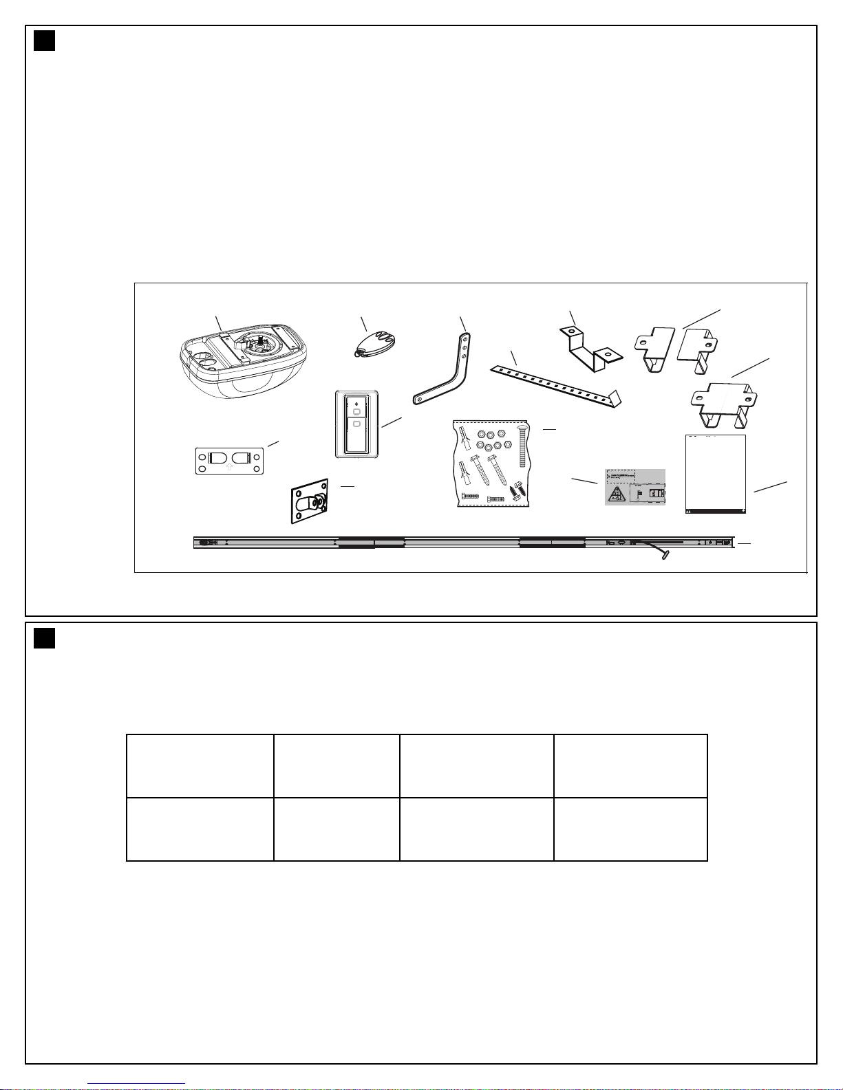
CARTON INVENTORY
2
our garage door opener, rail and hardware are packed in a single carton.
Y
1) Opener / powerhead
(
(2) Hand held transmitter (2)
(3) Wireless wall control
(4) Curved door arm
(5) Hanging bracket (2)
(6) Rail brackets (2)
(7) Lintel bracket
8) Door bracket
(
(9) Hardware bag
(10) Rail assembly (belt/chain)
(11) Manual
(12) Warning Labels
(13) Rail centre bracket
(14) Rail mounting bracket
3
RAIL SIZES AVAILABLE
DOOR HEIGHT:
Sectional Doors
Up to 2.5 m
RAIL LENGTH: CEILING FIXING
POINT: (standard)
3300 mm
Segmented
3150 mm
OVERALL LENGTH:
3450 mm
NOTE: The Ceiling Fixing Point is measured back from the lintel (see section 6 item 7 of “completed installation”). Also
allow 300 mm back from the fixing point for installation of the powerhead.
3

1
2
3
4
5
7
8
9
10
11
14
12
13
6
7
15
Drill Bits
10
TOOLS REQUIRED
10 (8x)
9 (8x)
8 (8x)
7 (1x)
6 (1x)
1 (1x)
2 (1x)
3 (6x)
4 (6x)
5 (6x)
4
HARDWARE PROVIDED
5
(1) Clevispin 80 mm
(2) R clip
(3) Hexagonal head screw M8
(4) Nut M8
(5) Flat washer M8
(6) Clevis Pin
(7) R clip
(8) Screw ST6 x 50 mm
(9) Screw ST6 x 18 mm
(10) Wallplug 8mm
COMPLETED INSTALLATION
6
As you proceed with the assembly, installation and adjustment procedures in this manual, you may find it helpful to
refer back to this illustration of a completed installation.
(9) Opener
(10) Manual release rope & handle
(11) Straight door arm
(12) Curved door arm
(13) Door bracket
(14) Rail mounting bracket
(15) Centre rail bracket
4
(1) Lintel bracket
(2) Belt/chain (hidden)
(3) Rail
(4) Trolley
(5) Rail connecting piece
(6) Rail bracket
(7) Hanging bracket
(8) Power cord

SP
123
123 2
1
2
3
4
7
6
5
CONTROL PANEL (located under the lens cover)
7
1. Terminal Block: used for external accessories (see chart below).
No Function Polarity Comment
Push button +ve
1
Common -ve
2
2 Common -ve
IR Sensor +ve
3
2. S Button: used to “SAVE” the REMOTE CONTROLS.
3. P Button: used to “PROGRAM” the DOOR LIMITS.
4. - Button: used to drive door DOWN.
5. + Button: used to drive door UP.
6. Blue Button: used to activate the door when remote controls are not available. Open - Stop - Close.
Dry contact input for push button wired wall controls:
Common terminal for push button and IR Beams:
Common terminal for push button and IR Beams:
IR Beam Input: (pulsing type only)
7. LEDs: 1. Remote Control Indicator
2. Program DOWN indicator, Door Operating & Passpoint indicator
3. Program UP indicator
5
 Loading...