

Page 1

MODELS ST1007, ST1012, ST1014
15" & 20" PLANERS
OWNER'S MANUAL
(For models manufactured since 03/16)
#17978MC
Phone: (360) 734-3482 • Online Technical Support: techsupport@woodstockint.com
COPYRIGHT © APRIL, 2016 BY WOODSTOCK INTERNATIONAL, INC.
V2.03.17
WARNING: NO PORTION OF THIS MANUAL MAY BE REPRODUCED IN ANY SHAPE OR FORM WITHOUT
THE WRITTEN APPROVAL OF WOODSTOCK INTERNATIONAL, INC.
Printed in China
Page 2

This manual provides critical safety instructions on the proper setup, operation, maintenance
and service of this machine/equipment.
Failure to read, understand and follow the instructions given in this manual may result in
serious personal injury, including amputation, electrocution or death.
The owner of this machine/equipment is solely responsible for its safe use. This responsibility
includes but is not limited to proper installation in a safe environment, personnel training and
usage authorization, proper inspection and maintenance, manual availability and
comprehension, application of safety devices, blade/cutter integrity, and the usage of
personal protective equipment.
The manufacturer will not be held liable for injury or property damage from negligence,
improper training, machine modications or misuse.
Some dust created by power sanding, sawing, grinding, drilling, and other construction
activities contains chemicals known to the State of California to cause cancer, birth defects or
other reproductive harm. Some examples of these chemicals are:
• Lead from lead-based paints.
• Crystalline silica from bricks, cement and other masonry products.
• Arsenic and chromium from chemically-treated lumber.
Your risk from these exposures varies, depending on how often you do this type of work. To
reduce your exposure to these chemicals: Work in a well ventilated area, and work with
approved safety equipment, such as those dust masks that are specially designed to lter out
microscopic particles.
Woodstock International, Inc. is committed to customer satisfaction. Our intent with this manual is to
include the basic information for safety, setup, operation, maintenance, and service of this product.
We stand behind our machines! In the event that questions arise about your machine, please contact
Woodstock International Technical Support at (360) 734-3482 or send e-mail to:
tech-support@shopfox.biz. Our knowledgeable sta will help you troubleshoot problems and
process warranty claims.
If you have comments about this manual, please contact us at:
Woodstock International, Inc.
Attn: Technical Documentation Manager
P.O. Box 2309
Bellingham, WA 98227
manuals@woodstockint.com
Page 3

Table of Contents
INTRODUCTION .................................................... 2
Contact Info .................................................................... 2
Machine Descriptions ................................................. 2
Manual Accuracy .......................................................... 2
Machine Data Sheet .................................................... 3
MACHINE FEATURES ............................................. 5
CONTROLS & COMPONENTS ................................ 6
SAFETY .................................................................. 8
Safety Instructions for Machinery .......................... 8
Additional Safety for Planers ..................................10
ELECTRICAL ......................................................... 11
Circuit Requirements ................................................11
Grounding Requirements .......................................12
Extension Cords ..........................................................12
SETUP .................................................................. 13
Unpacking .....................................................................13
Items Needed for Setup ........................................... 13
Inventory .......................................................................14
Hardware Recognition Chart .................................15
Lifting & Moving ......................................................... 18
Assembly .......................................................................19
OPERATIONS ....................................................... 23
Overview .......................................................................23
Workpiece Inspection ............................................... 24
Wood Types .................................................................. 24
Planing Tips ..................................................................25
Cutting Problems .......................................................25
Depth of Cut ................................................................. 26
Setting Feed Rate .......................................................28
Adjusting/Replacing Knives (ST1007) ................. 28
Rotating/Replacing .................................................... 30
Cutterhead Inserts .....................................................30
(ST1012/ST1014) ......................................................... 30
ACCESSORIES ...................................................... 32
MAINTENANCE .................................................... 35
General ........................................................................... 35
Schedule ........................................................................ 35
Cleaning/Protecting .................................................. 35
Basic Adjustment Tools ............................................36
Optional Adjustment Tools .....................................36
Lubrication .................................................................... 37
Tensioning/Replacing V-Belts ................................38
Anti-Kickback Pawls...................................................39
SERVICE ............................................................... 40
Troubleshooting .........................................................40
Adjusting Feed Rollers, Chip Breaker
& Pressure Bar ..............................................................42
Adjusting Roller Spring Tension ............................46
Positioning Chip Deflector ...................................... 47
Adjusting Table Parallelism ..................................... 47
ST1007 & ST1012 Electrical Components ..........51
ST1007 Wiring Diagram ...........................................52
ST1012 Wiring Diagram ...........................................53
ST1014 Electrical Components .............................54
ST1014 Wiring Diagram ...........................................55
ST1007/ST1012 PARTS ....................................... 56
ST1007 Main Breakdown ......................................... 56
ST1007/ST1012 Headstock Parts Diagram ....... 58
ST1007/ST1012 Gearbox Diagram
& Parts List .....................................................................60
ST1007/ST1012 Lower Table Diagram
& Parts List .....................................................................61
ST1007/ST1012 Upper Table Diagram
& Parts List .....................................................................62
ST007/ST1012 Label Placement ............................ 63
ST1014 PARTS ..................................................... 64
ST1014 Headstock Breakdown ..............................64
ST1014 Gearbox Breakdown and Parts List ......67
ST1014 Cabinet Breakdown ..................................68
ST1014 Table Breakdown and Parts List ............70
ST1014 Columns Breakdown and Parts List .....71
ST1014 Label Placement .........................................72
WARRANTY .......................................................... 74
Warranty Registration ...............................................75
Page 4

We are proud to provide a high-quality owner’s
manual with your new machine!
We
instructions, specifications, drawings, and photographs
contained inside. Sometimes we make mistakes, but
our policy of continuous improvement also means
that
you receive will be
slightly different than what is shown in the manual
If you find this to be the case, and the difference
between the manual and machine leaves you confused about a procedure
check our website for
an updated version. W
manuals and
manual
www.
woodstockint
Alternatively, you can call our Technical Support for
help. Before calling, make sure you write down the
Manufacture Date
from the
machine ID label (see below). Also, if available, have
a copy of your
on hand.
This information is required for all Tech Support calls.
MODEL XXXX
MACHINE NAME
Motor:
Specification:
Specification:
Specification:
Specification:
Weight:
Specifications
To reduce risk of serious personal injury when using this
machine:
1. Read & understand owner’s manual before operating.
2. Always wear approved eye protection and respirator.
3. Only plug power cord into a grounded outlet.
4. Only use this machine to collect wood dust/chips—never
use to collect glass, metal, liquids, asbestos, silica,
animal parts, biohazards, burning material/ashes, etc.
5. Always disconnect power before servicing or cleaning.
6. Do not expose to rain or wet areas.
7. Keep hands, long hair, and loose clothing away from
inlet.
8. Never leave machine unattended while it is running.
9. Do not use if cord/plug becomes damaged—promptly
repair and protect cord from future damage.
10. Do not use without dust bag or filters in place.
11. Always wear a respirator when emptying bags.
12. Prevent unauthorized use by children or untrained users.
Date
Serial Number
Manufactured for Woodstock in Taiwan
WARNING!
We are committed to customer satisfaction. If you
have any questions or need help, use the information
below to contact us.
IMPORTANT: Before contacting, please get the
original purchase receipt, serial number, and
manufacture date of your machine. This information is required for all Technical Support calls and
it will help us help you faster.
Email: manuals@woodstockint.com
INTRODUCTION
Contact Info
Woodstock International Technical Support
Phone: (360) 734-3482
Email: techsupport@woodstockint.com
We want your feedback on this manual. What did
you like about it? Where could it be improved?
Please take a few minutes to give us feedback.
Technical Documentation Manager
P.O. Box 2309
Bellingham, WA 98227
Manual Accuracy
made every effort to be exact with the
sometimes the machine
.
,
e post current
updates for free on our website at
.com.
and Serial Number
original purchase receipt
Machine Descriptions
Following are the differences between the models
covered in this manual:
• ST1007 = 15", 3 HP, with 3-Knife Cutterhead
• ST1012 = 15", 3 HP, with Helical Cutterhead
• ST1014 = 20", 5 HP, with Helical Cutterhead
-2-
Manufacture
Date
Serial Number
ST1007/12/14 15" & 20" Planers (Mfd. Since 3/16)
Page 5

Machine Data Sheet
MACHINE
SPECIFICATIONS
© Woodstock International, Inc. • Phone: (800) 840-8420 • Web: www.woodstockint.com
MODEL ST1007, ST1012, & ST1014 PLANERS
Model Number ST1007 ST1012 ST1014
Product Dimensions
Weight
Width (side-to-side) x Depth (frontto-back) x Height
Foot Print (Length x Width) 22-1/2 x 22 in. 23-1/2 x 23-1/2 in.
Shipping Dimensions
Type Wood Crate
Weight 660 lbs. 683 lbs. 874 lbs.
Width (side-to-side) x Depth (frontto-back) x Height
Electrical
Power Requirement 240V, Single-Phase, 60 Hz
Full-Load Current Rating 15A 19A
Minimum Circuit Size 20A 30A
Connection Type Cord & Plug
Power Cord Included Yes
Power Cord Length 6 ft. 6-1/2 ft.
Power Cord Gauge 12 AWG
Plug Included Yes
Included Plug Type 6-20 L6-30
Switch Type Magnetic Switch w/Overload Protection
Motor
Type TEFC Capacitor-Start Induction
Horsepower 3 HP 5 HP
Phase Single-Phase
Amps 15A 19A
Speed 3450 RPM
Power Transfer Belt Drive
Bearings Sealed & Permanently Lubricated
Manufacturer Specifications
Country of Origin China
Warranty 2 Years
Approx. Assembly & Setup Time 30 Minutes
Serial Number Location ID Label
ISO 9001 Factory No
Certified by NRTL No
640 lbs. 660 lbs. 771 lbs.
42 x 32-1/2 x 46 in. 55-1/2 x 43-1/2 x 46 in.
30 x 36 x 47 in. 43 x 29 x 48 in.
ST1007/12/14 15" & 20" Planers (Mfd. Since 3/16)
-3-
Page 6

Model Number ST1007 ST1012 ST1014
Main Specifications
Planer Size 15 in. 20 in.
Max. Cut Width 15 in. 20 in.
Max. Stock Thickness 8 in.
Min. Stock Thickness 3/16 in.
Min. Stock Length 8 in. 8 in. 8 in.
Number of Cuts Per Inch 42, 63 56, 104 104, 83
Number of Cuts Per Minute 15,000 24,000
Cutterhead Speed 4800 RPM
Planing Feed Rate 16, 30 RPM
Max. Cut Depth Planing Full Width 3/32 in. 1/8 in.
Max. Cut Depth Planing 6-Inch Wide
Board
Dust Port Size 4 in. 5 in.
Cutterhead Info
Cutterhead Type 3-Knife Helical Helical
Cutterhead Diameter 3 in. 3
Number of Knives 3 N/A N/A
Knife Type HSS, Single-Sided, Solid N/A N/A
Knife Length 15 in. N/A N/A
Knife Width 1 in. N/A N/A
1
Knife Thickness
⁄8 in. N/A N/A
Knife Adjustment Springs or Jack Screws N/A N/A
Number of Cutter Rows N/A 5 5
Number of Indexable Cutters N/A 75 100
Cutter Insert Type N/A Indexable Carbide Indexable Carbide
Cutter Insert Length N/A 15 mm 15 mm
Cutter Insert Width N/A 15 mm 15 mm
Cutter Insert Thickness N/A 2.5 mm 2.5 mm
Table Info
Table Movement 8 in.
Table Bed Length 20 in. 25
Table Bed Width 15 in. 20 in.
Table Bed Thickness 1-3/4 in.
Floor-to-Table Height 27 – 35 in. 26
Construction
Table Precision-Ground Cast Iron
Body Cast Iron
Stand Steel
Cutterhead Assembly Steel
Infeed Roller Serrated Steel
Outfeed Roller Rubber
Paint Type/Finish Powder Coated
1/8 in.
1
⁄8 in.
3
⁄4 in.
1
⁄2–341⁄2 in.
-4-
ST1007/12/14 15" & 20" Planers (Mfd. Since 3/16)
Page 7
MACHINE FEATURES
risk of
serious injury, read this
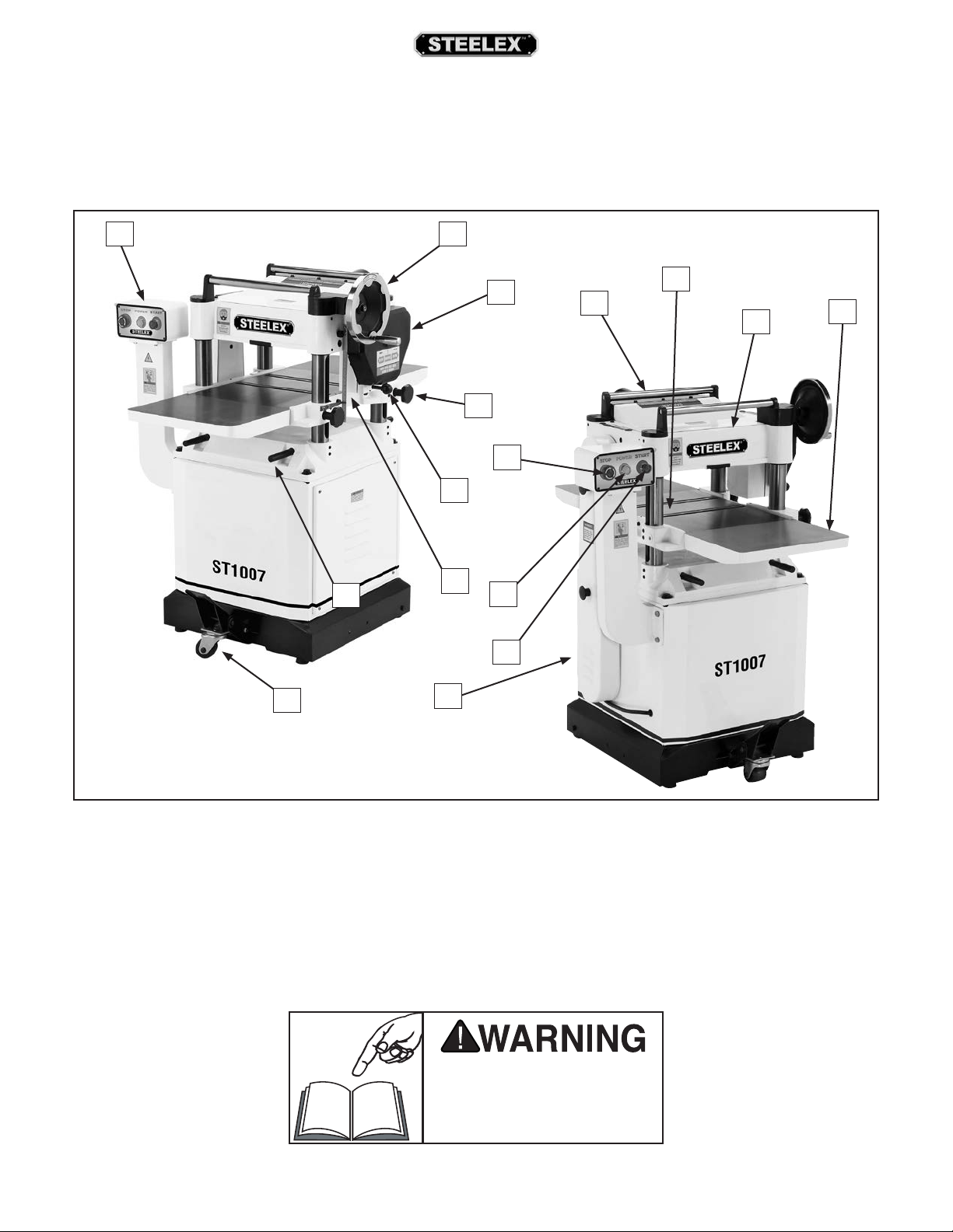
The instructions in this manual will be easier to understand if you become familiar with the location and names
of the basic features of your new machine. Use the list below with the letters to identify the external features of
the planer.
BA
C
D
M
E
F
G
H
P
N
O
J
K
I
L
A. Control Panel
B. Table Height Handwheel
C. Feed Roller Gearbox
D. Table Lock Knob
E. Feed Rate Selector
F. Table Height Scale
G. Retractable Lifting Rods
H. Caster Wheel and Lock
ST1007/12/14 15" & 20" Planers (Mfd. Since 3/16)
I. Headstock
J. Return Roller
K. Table Roller
L. Cast Iron Wing
M. Emergency STOP Button
N. Power Lamp
O. START Button
P. Drive Belt Cover
To reduce your
entire manual BEFORE using
machine.
-5-
Page 8
To reduce your risk of
serious injury, read this
entire manual BEFORE using
machine.
CONTROLS & COMPONENTS
Refer to the Figures 1-3 and the following descriptions to become familiar with the basic controls and
components of this machine. Understanding these
items and how they work will help you understand
the rest of the manual and stay safe when operating
this machine.
A. Control Panel for Magnetic Switch: Green
START button turns motor ON when pressed.
Red Emergency STOP button turns motor OFF
when pressed; for safety purposes, this button
will remain depressed and prevent restarting
until reset. Reset by rotating clockwise until it
pops out.
B. Table Height Handwheel: Raises and lowers
table to accommodate different workpiece
thicknesses. One complete revolution moves
the table approximately
1
⁄16".
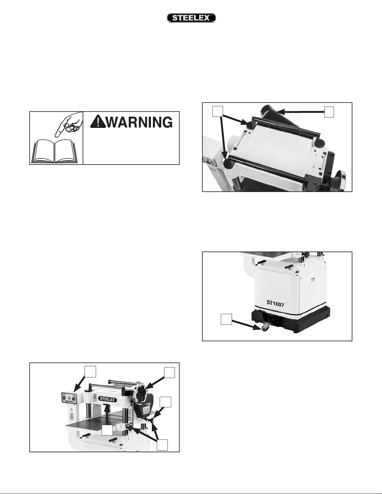
F. Return Rollers: Assist sliding workpiece back to
operator following planing operation.
G. Dust Port: Connects to a dust collection system
to extract shavings and dust during operation.
F
Figure 2. Return rollers and dust port.
H. Mobile-Base Foot Pedal: When engaged, lifts
machine onto casters for repositioning. When
disengaged, allows machine to rest firmly on
floor during operations.
G
C. Feed Rate Control Knob: Selects 30 FPM feed
rate when pushed in, and 16 FPM feed rate
when pulled out.
D. Table Locks: Secure table height position when
tightened.
E. Depth-of-Cut Limiter: Limits depth of cut to a
maximum of
Figure 1. Table elevation and feed controls.
-6-
1
⁄8" at full width.
A
E
B
C
D
H
Figure 3. Mobile-base foot pedal.
ST1007/12/14 15" & 20" Planers (Mfd. Since 3/16)
Page 9
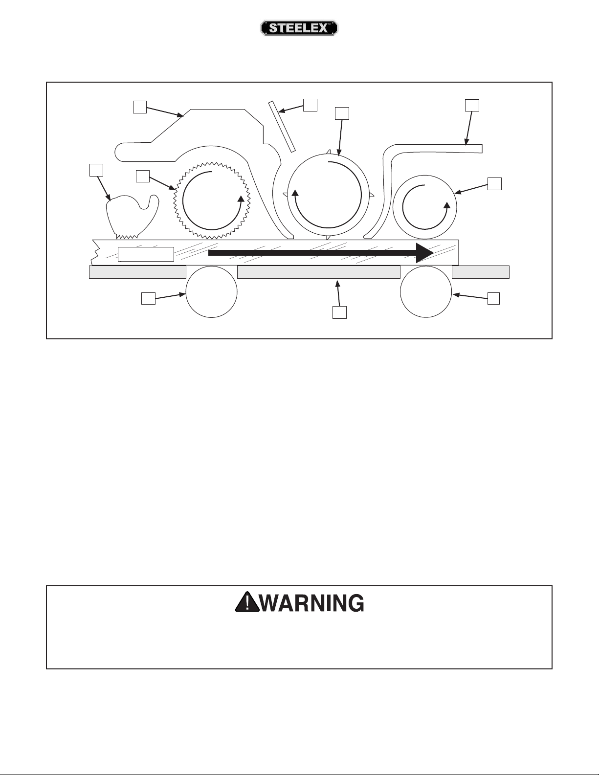
Internal Components
FRONT
A
A. Anti-Kickback Fingers: Provide additional safe-
ty for the operator.
B. Serrated Infeed Roller: Pulls the workpiece
toward the cutterhead.
C. Chip Breaker: Breaks off chips created by the
cutterhead to prevent tear out and diverts the
chips to the dust hood.
D. Chip Deflector: Directs chips into the dust
hood.
E. Cutterhead: Holds the knives/indexable car-
bide inserts that remove material from the
workpiece.
C
B
Workpiece
H H
Figure 4. Workpiece path and major planing components (side cutaway view).
D
E
I
F. Pressure Bar: Stabilizes the workpiece as it
leaves the cutterhead and assists in deflecting
wood particles toward the dust hood (ST1014
only).
G. Outfeed Roller: Pulls the workpiece through
the planer.
H. Table Rollers: Provide upward pressure on the
workpiece, enabling the feed rollers to pull the
workpiece along.
I. Planer Table: Provides a smooth and level path
for the workpiece as it moves through the
planer.
F
REAR
G
Like all machinery there is potential danger when operating this machine. Accidents are frequently
caused by lack of familiarity or failure to pay attention. Use this machine with respect and caution to
decrease the risk of operator injury. If normal safety precautions are overlooked or ignored, serious
personal injury may occur.
ST1007/12/14 15" & 20" Planers (Mfd. Since 3/16)
-7-
Page 10
SAFETY
For Your Own Safety, Read Instruction Manual
Before Operating This Machine
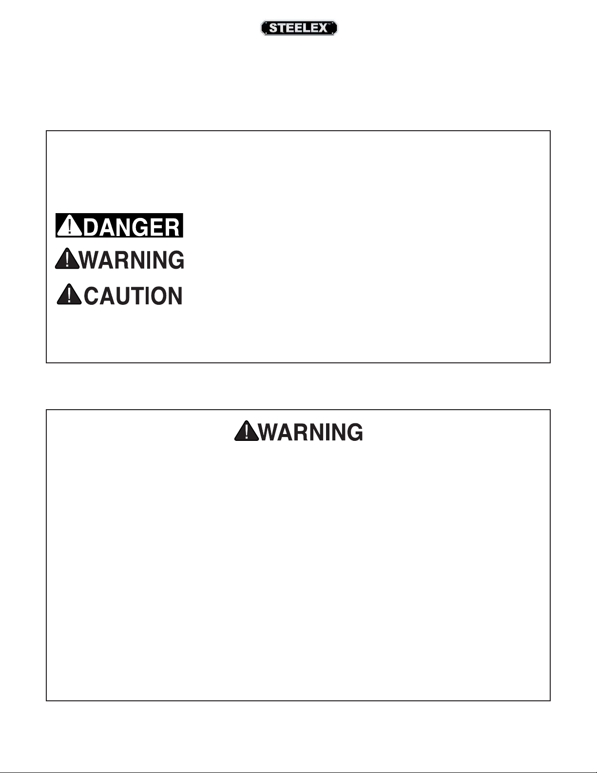
The purpose of safety symbols is to attract your attention to possible hazardous conditions. This
manual uses a series of symbols and signal words intended to convey the level of importance of the
safety messages. The progression of symbols is described below. Remember that safety messages
by themselves do not eliminate danger and are not a substitute for proper accident prevention measures. Always use common sense and good judgment.
Indicates an imminently hazardous situation which, if not avoided, WILL
result in death or serious injury.
Indicates a potentially hazardous situation which, if not avoided, COULD
result in death or serious injury.
Indicates a potentially hazardous situation which, if not avoided, MAY
result in minor or moderate injury. It may also be used to alert against
unsafe practices.
This symbol is used to alert the user to useful information about proper
NOTICE
operation of the machine.
Safety Instructions for Machinery
OWNER’S MANUAL. Read and understand this own-
er’s manual BEFORE using machine.
TRAINED OPERATORS ONLY. Untrained operators
have a higher risk of being hurt or killed. Only
allow trained/supervised people to use this machine.
When machine is not being used, disconnect power,
remove switch keys, or lock-out machine to prevent
unauthorized use—especially around children. Make
workshop kid proof!
DANGEROUS ENVIRONMENTS. Do not use machinery in areas that are wet, cluttered, or have poor
lighting. Operating machinery in these areas greatly
increases the risk of accidents and injury.
MENTAL ALERTNESS REQUIRED. Full mental alertness is required for safe operation of machinery.
Never operate under the influence of drugs or alcohol, when tired, or when distracted.
ELECTRICAL EQUIPMENT INJURY RISKS. You can
be shocked, burned, or killed by touching live electrical components or improperly grounded machinery. To reduce this risk, only allow qualified service
personnel to do electrical installation or repair work,
and always disconnect power before accessing or
exposing electrical equipment.
DISCONNECT POWER FIRST.
machine from power supply BEFORE making adjustments, changing tooling, or servicing machine. This
pr
events an injury risk from unintended startup or
contact with live electrical components.
EYE PROTECTION. Always wear ANSI-approved safety glasses or a face shield when operating or observing machinery to reduce the risk of eye injury or
blindness from flying particles. Everyday eyeglasses
are NOT approved safety glasses.
Always disconnect
-8-
ST1007/12/14 15" & 20" Planers (Mfd. Since 3/16)
Page 11

WEARING PROPER APPAREL. Do not wear clothing, apparel or jewelry that can become entangled
in moving parts. Always tie back or cover long hair.
Wear non-slip footwear to reduce risk of slipping and
losing control or accidentally contacting cutting tool
or moving parts.
HAZARDOUS DUST. Dust created by machinery
operations may cause cancer, birth defects, or longterm respiratory damage. Be aware of dust hazards
associated with each workpiece material. Always
wear a NIOSH-approved respirator to reduce your
risk.
HEARING PROTECTION. Always wear hearing protection when operating or observing loud machinery. Extended exposure to this noise without hearing
protection can cause permanent hearing loss.
REMOVE ADJUSTING TOOLS. Tools left on machinery can become dangerous projectiles upon startup.
Never leave chuck keys, wrenches, or any other tools
on machine. Always verify removal before starting!
USE CORRECT TOOL FOR THE JOB. Only use this
tool for its intended purpose—do not force it or an
attachment to do a job for which it was not designed.
Never make unapproved modifications—modifying
tool or using it differently than intended may result
in malfunction or mechanical failure that can lead to
personal injury or death!
AWKWARD POSITIONS. Keep proper footing and
balance at all times when operating machine. Do
not overreach! Avoid awkward hand positions that
make workpiece control difficult or increase the risk
of accidental injury.
CHILDREN & BYSTANDERS. Keep children and
bystanders at a safe distance from the work area.
Stop using machine if they become a distraction.
GUARDS & COVERS. Guards and covers reduce accidental contact with moving parts or flying debris.
Make sure they are properly installed, undamaged,
and working correctly BEFORE operating machine.
FORCING MACHINERY. Do not force machine. It will
do the job safer and better at the rate for which it was
designed.
NEVER STAND ON MACHINE. Serious injury may
occur if machine is tipped or if the cutting tool is
unintentionally contacted.
STABLE MACHINE. Unexpected movement during
operation greatly increases risk of injury or loss of
control. Before starting, verify machine is stable and
mobile base (if used) is locked.
USE RECOMMENDED ACCESSORIES. Consult this
owner’s manual or the manufacturer for recommended accessories. Using improper accessories will
increase the risk of serious injury.
UNATTENDED OPERATION. To reduce the risk of
accidental injury, turn machine OFF and ensure all
moving parts completely stop before walking away.
Never leave machine running while unattended.
MAINTAIN WITH CARE. Follow all maintenance
instructions and lubrication schedules to keep
machine in good working condition. A machine that
is improperly maintained could malfunction, leading
to serious personal injury or death.
DAMAGED PARTS. Regularly inspect machine for
damaged, loose, or mis-adjusted parts—or any condition that could affect safe operation. Immediately
repair/replace BEFORE operating machine. For your
own safety, DO NOT operate machine with damaged
parts!
MAINTAIN POWER CORDS. When disconnecting
cord-connected machines from power, grab and
pull the plug—NOT the cord. Pulling the cord may
damage the wires inside. Do not handle cord/plug
with wet hands. Avoid cord damage by keeping it
away from heated surfaces, high traffic areas, harsh
chemicals, and wet/damp locations.
EXPERIENCING DIFFICULTIES. If at any time you
experience difficulties performing the intended operation, stop using the machine! Contact our Technical
Support at (570) 546-9663.
ST1007/12/14 15" & 20" Planers (Mfd. Since 3/16)
-9-
Page 12

Additional Safety for Planers
Amputation, serious cuts, entanglement, or death can occur from contact with rotating cutterhead
or other moving parts! Flying chips can cause blindness or eye injuries. Workpieces or knives thrown
by cutterhead can strike nearby operator or bystanders with deadly force. To reduce the risk of these
hazards, operator and bystanders MUST completely heed hazards and warnings below.
KICKBACK. Know how to reduce the risk of kickback
and kickback-related injuries. “Kickback” occurs during the operation when the workpiece is ejected
from the machine at a high rate of speed. Kickback
is commonly caused by poor workpiece selection,
unsafe feeding techniques, or improper machine
setup/maintenance. Kickback injuries typically occur
as follows: (1) operator/bystanders are struck by the
workpiece, resulting in impact injuries (i.e., blindness,
broken bones, bruises, death); (2) operator’s hands
are pulled into blade, resulting in amputation or
severe lacerations.
AVOID CONTACT WITH MOVING PARTS. Never
remove guards/covers or reach inside the planer
during operation or while connected to power. You
could be seriously injured if you accidentally touch
the spinning cutterhead or get entangled in moving parts. If a workpiece becomes stuck or sawdust
removal is necessary, turn planer OFF and disconnect
power before clearing.
DULL/DAMAGED KNIVES/INSERTS. Only use sharp,
undamaged knives/inserts. Dull or damaged knives/
inserts increase the risk of kickback.
INSPECTING STOCK. To reduce the risk of kickback
injuries or machine damage, thoroughly inspect and
prepare the workpiece before cutting. Verify workpiece is free of nails, staples, loose knots or foreign
material. Workpieces with minor warping should be
jointed first or planed with the cupped side facing
the table.
PLANING CORRECT MATERIAL. Only plane natural
wood stock with this planer. DO NOT plane MDF,
OSB, plywood, laminates or other synthetic materials
that can break up inside the planer and be ejected
towards the operator.
LOOKING INSIDE PLANER. Wood chips fly around
inside the planer at a high rate of speed during
operation. To avoid injury from flying material, DO
NOT look inside planer during operation.
CUTTING LIMITATIONS. To reduce the risk of kickback hazards or damage to the machine, do not
exceed the maximum depth of cut or minimum
board length and thickness found in the Data Sheet.
Only feed one board at a time.
INFEED ROLLER CLEARANCE. The infeed roller is
designed to pull material into the spinning cutterhead. To reduce the risk of entanglement, keep
hands, clothing, jewelry, and long hair away from the
infeed roller during operation.
FEED WORKPIECE PROPERLY. To reduce the risk of
kickback, never start planer with workpiece touching cutterhead. Allow cutterhead to reach full speed
before feeding, and do not change feed speed during cutting operation.
WORKPIECE SUPPORT. To reduce the risk of kickback, always make sure workpiece can move completely across table without rocking or tipping. Use
auxiliary support stands for long stock.
BODY PLACEMENT. Stand to one side of planer
during the entire operation to avoid getting hit if
kickback occurs.
GRAIN DIRECTION. Planing across the grain is hard
on the planer and may cause kickback. Plane in the
same direction or at a slight angle with the wood
grain.
-10-
SECURE KNIVES/INSERTS. Loose knives or improperly set inserts can become dangerous projectiles or
cause machine damage. Always verify knives/inserts
are secure and properly adjusted before operation.
ST1007/12/14 15" & 20" Planers (Mfd. Since 3/16)
Page 13
ELECTRICAL
Circuit Requirements
Serious personal injury could occur if you connect the machine to the power source before
you have completed the set up process. DO
NOT connect the machine to the power source
until instructed to do so.
This machine must be connected to the correct size
and type of power supply circuit, or fire or electrical
damage may occur. Read through this section to
determine if an adequate power supply circuit is
available. If a correct circuit is not available, an electrician or qualified service personnel MUST install one
before you can connect the machine to power.
A power supply circuit includes all electrical equipment between the breaker box or fuse panel in the
building and the machine. The power supply circuit
used for this machine must be sized to safely handle
the full-load current drawn from the machine for an
extended period of time. (If this machine is connected to a circuit protected by fuses, use a time delay
fuse marked D.)
Incorrectly wiring or
grounding this machine can
cause electrocution, fire, or
machine damage. To reduce
this risk, only an electrician
or qualified service personnel should do any required
electrical work on this
machine.
Full-Load Current Rating
The full-load current rating is the amperage a
machine draws at 100% of the rated output power.
On machines with multiple motors, this is the amperage drawn by the largest motor or sum of all motors
and electrical devices that might operate at one time
during normal operations.
ST1007/ST1012
Full-Load Current Rating.......................... 15 Amps
ST1014
Full-Load Current Rating.......................... 19 Amps
This machine is prewired to operate on a power supply circuit that has a verified ground and meets the
following requirements:
ST1007/ST1012
Circuit Requirements
Nominal Voltage ..............208V, 220V, 230V, 240V
Cycle ............................................................... 60 Hz
Phase ................................................. Single-Phase
Power Supply Circuit ................................20 Amps
Plug/Receptacle ....................................NEMA 6-20
ST1014
Circuit Requirements
Nominal Voltage ..............208V, 220V, 230V, 240V
Cycle ............................................................... 60 Hz
Phase ................................................. Single-Phase
Power Supply Circuit ................................30 Amps
Plug/Receptacle ..................................NEMA L6-30
The circuit requirements listed in this manual
apply to a dedicated circuit—where only
one machine will be running at a time. If this
machine will be connected to a shared circuit
where multiple machines will be running at the
same time, consult a qualified electrician to
ensure that the circuit is properly sized for safe
operation.
ST1007/12/14 15" & 20" Planers (Mfd. Since 3/16)
-11-
Page 14

an electrician or qualified service personnel,
and it must comply with all local codes and
Grounding
Requirements
This machine MUST be grounded. In the event of certain types of malfunctions or breakdowns, grounding
provides a path of least resistance for electric current
to travel—in order to reduce the risk of electric shock.
L6-30 GROUNDED
LOCKING
RECEPTACLE
Grounding Prong
is Hooked
L6-30
LOCKING
PLUG
Improper connection of the equipment-grounding
wire will increase the risk of electric shock. The wire
with green insulation (with/without yellow stripes) is
the equipment-grounding wire. If repair or replacement of the power cord or plug is necessary, do not
connect the equipment-grounding wire to a live
(current carrying) terminal.
Check with a qualified electrician or service personnel if you do not understand these grounding
requirements, or if you are in doubt about whether
the tool is properly grounded. If you ever notice that
a cord or plug is damaged or worn, disconnect it
from power, and immediately replace it with a new
one.
This machine is equipped with a power cord that
has an equipment-grounding wire and a grounding
plug. Only insert plug into a matching receptacle
(outlet) that is properly installed and grounded in
accordance with all local codes and ordinances. DO
NOT modify the provided plug!
Current Carrying Prongs
Figure 6. Typical L6-30 plug and receptacle.
No adapter should be used with plug. If plug
does not fit available receptacle, or if machine
must be reconnected for use on a different type
of circuit, reconnection must be performed by
ordinances.
GROUNDED
6-20 RECEPTACLE
Current Carrying Prongs
6-20 PLUG
Grounding Prong
Figure 5. Typical 6-20 plug and receptacle.
The machine must be properly set up before
it is safe to operate. DO NOT connect this
machine to the power source until instructed
to do later in this manual.
-12-
Extension Cords
We do not recommend using an extension cord
with this machine. Extension cords cause voltage
drop, which may damage electrical components and
shorten motor life. Voltage drop increases with longer extension cords and smaller gauge sizes (higher
gauge numbers indicate smaller sizes).
Any extension cord used with this machine must
contain a ground wire, match the required plug and
receptacle, and meet the following requirements:
Minimum Gauge Size ................................ 12 AWG
Maximum Length (Shorter is Better) ............50 ft.
ST1007/12/14 15" & 20" Planers (Mfd. Since 3/16)
Page 15
SETUP
Items Needed for
This machine presents
serious injury hazards
to untrained users. Read
through this entire manual to become familiar with
the controls and operations before starting the
machine!
UNPLUG-power cord before
you do any assembly or
adjustment tasks! Otherwise,
serious personal injury to
you or others may occur!.
Unpacking
The Models ST1007/ST1012/ST1014 were carefully
packed when they left our warehouse. If you discover your machine is damaged immediately call your
dealer.
Setup
The following items are needed, but not included, to
set up your machine.
Description Qty
• Additional People ....................................................... 1
• Safety Glasses ......................................... 1 Per Person
• Forklift (rated for at least 1000 lbs.) ..................... 1
• Cleaner/Degreaser...................................As Needed
• Disposable Shop Rags............................As Needed
• Phillips Screwdriver #2 .............................................. 1
• Open-End Wrench or Socket 12mm .................... 1
• Open-End Wrench or Socket 14mm .................... 1
• Hex Wrenches 3, 4, 5, 6, 8mm ..........................1 Ea.
• Straightedge 4' ............................................................ 1
• Dust Collection System ............................................ 1
• 4" Dust Hose w/Clamps ............................................ 1
Save the containers and all packing materials for possible inspection by the carrier or its agent. Otherwise,
filing a freight claim can be difficult.
When you are completely satisfied with the condition
of your shipment, you should inventory the contents.
SUFFOCATION HAZARD!
Immediately discard all plastic bags and packing materials to eliminate choking/suffocation hazards for children
and animals.
ST1007/12/14 15" & 20" Planers (Mfd. Since 3/16)
-13-
Page 16
Inventory
The following is a list of items shipped with your
machine. Before beginning setup, lay these items out
and inventory them.
Note: If you cannot find an item on this list, carefully
check around/inside the machine and packaging materials. Often, these items get lost in packaging materials
while unpacking or they are pre-installed at the factory.
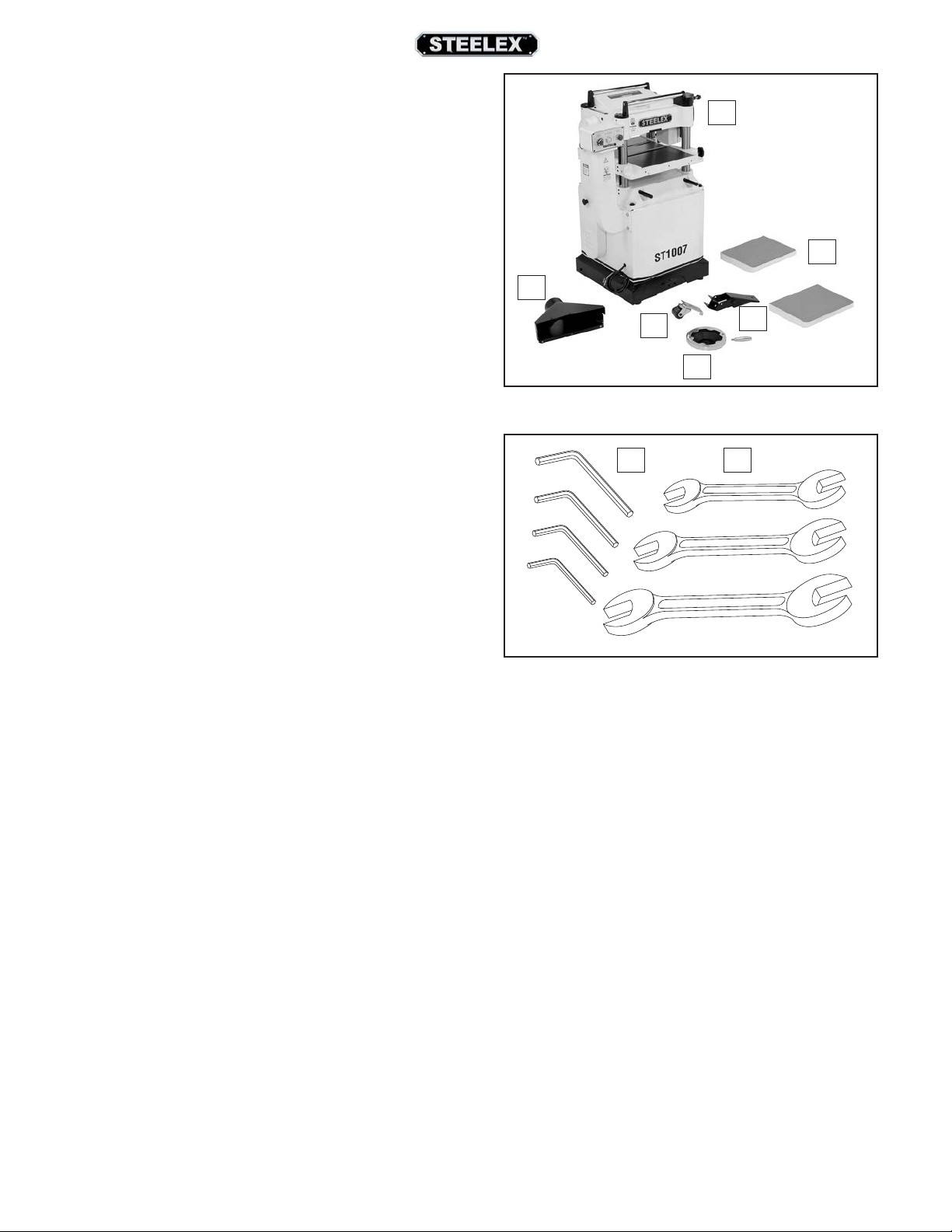
Component Inventory (Figure 7) Qty
A. Planer .............................................................................. 1
B. Dust Hood ..................................................................... 1
C. Caster Assembly .......................................................... 1
D. Foot Lifting Lever and Pin........................................ 1
E. Handwheel and Handle............................................ 1
F. Extension Wings .......................................................... 2
A
F
B
C
E
Figure 7. Component inventory.
D
Tools (Figure 8)
G. Hex Wrenches 2.5, 3, 4, 6mm............................1 Ea.
H. Wrenches 8/10, 14/17, 17/19mm ....................1 Ea.
Hardware (See Hardware Recognition Chart)
I. Knife-Setting Gauge (Not shown) ........................ 1
J. Flat Washers 8mm (Wing) ........................................ 6
K. Lock Washers 8mm (Wing) ...................................... 6
L. Hex Bolts M8-1.25 x 30 (Wing) ............................... 6
M. Set Screws M8-1.25 x 20 (Wing) ............................ 4
N. Cap Screws M8-1.25 x 20 (Dust Hood) ................ 3
O. Hex Bolts M6-1 x 10 (Dust Hood) .......................... 3
P. Flat Washers 6mm (Dust Hood) ............................ 3
Q. Hex Nuts M6-1 (Dust Hood) .................................... 3
R. Key 4 x 4 x 20 (Handwheel) ..................................... 1
S. Bushing (Handwheel) ................................................ 1
T. Hex Nut M12-1.75 (Handwheel) ............................ 1
U. Flat Washer 12mm (Handwheel) ........................... 1
G H
Figure 8. Tool inventory.
-14-
ST1007/12/14 15" & 20" Planers (Mfd. Since 3/16)
Page 17
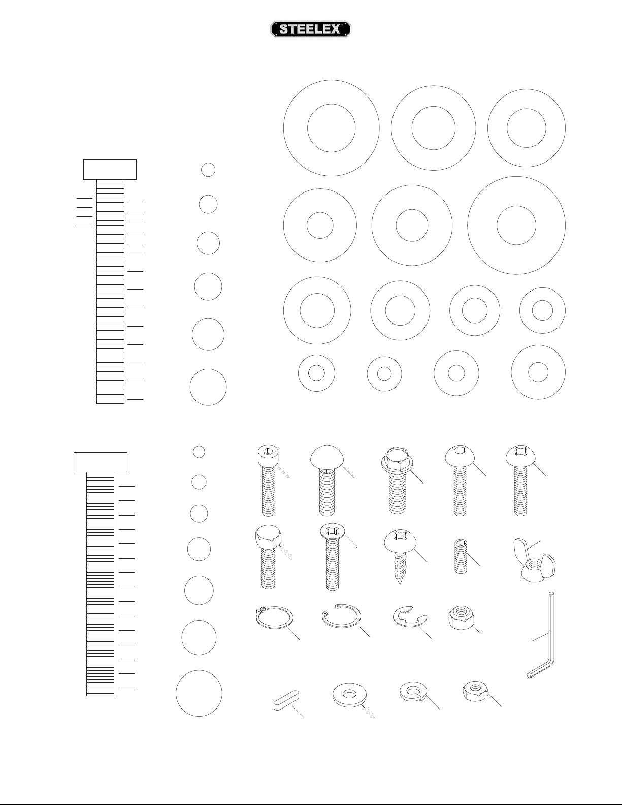
Hardware Recognition Chart
USE THIS CHART TO IDENTIFY
HARDWARE DURING THE
INVENTORY/ASSEMBLY
PROCESS.
1
⁄4"
3
⁄8"
1
⁄2"
5
⁄8"
⁄16" INCH APART
1
LINES ARE
5
7
9
3
7
1
1
1
1
2
2
2
2
3
⁄16"
⁄16"
⁄16"
⁄4"
⁄8"
1
⁄4"
1
⁄2"
3
⁄4"
1
⁄4"
1
⁄2"
3
⁄4"
#10
1
⁄4"
5
⁄16"
3
⁄8"
7
⁄16"
1
⁄2"
WASHERS ARE MEASURED BY THE INSIDE DIAMETER
S
A
W
A
W
H
S
E
H
H
S
E
H
S
D
R
E
8mm
A
W
D
R
7
⁄16"
D
R
E
A
W
#10
D
I
A
R
M
E
T
E
5
⁄8"
I
A
I
A
I
A
M
E
T
E
R
R
M
E
T
E
R
M
E
T
E
R
E
H
S
10mm
A
D
R
E
H
3
S
⁄8"
A
W
D
I
A
R
M
E
H
E
S
T
E
A
R
W
4mm
R
W
D
I
A
R
E
H
S
A
W
D
I
I
A
M
E
R
M
E
T
⁄16"
E
T
E
E
R
H
S
A
A
I
D
M
R
E
E
H
S
D
I
R
E
H
S
A
W
T
5
E
⁄16"
R
A
W
A
M
E
T
E
R
9
A
M
R
E
T
5mm
H
S
A
W
R
E
12mm
W
D
I
R
A
E
M
E
⁄2"
I
A
E
H
S
T
E
R
M
E
T
E
R
D
I
A
R
M
E
E
H
1
T
S
⁄4"
E
A
R
W
D
I
A
R
M
E
T
E
A
R
W
1
D
6mm
MEASURE BOLT DIAMETER BY PLACING INSIDE CIRCLE
LINES ARE 1MM APART
5mm
10mm
15mm
20mm
25mm
30mm
35mm
40mm
45mm
50mm
55mm
60mm
65mm
70mm
75mm
4mm
5mm
6mm
8mm
10mm
12mm
16mm
Cap
Screw
Hex
Bolt
External
Retaining
Ring
Key
Carriage
Bolt
Flat
Head
Screw
Internal
Retaining
Ring
Flat Washer
Flange
Bolt
Tap
Screw
E-Clip
Lock
Washer
Button
Head
Screw
Set
Screw
Lock
Nut
Hex
Nut
Phillips
Head
Screw
Wing
Nut
Hex
Wrench
ST1007/12/14 15" & 20" Planers (Mfd. Since 3/16)
-15-
Page 18
Cleanup
The unpainted surfaces of your machine are coated
with a heavy-duty rust preventative that prevents
corrosion during shipment and storage. This rust preventative works extremely well, but it will take a little
time to clean.
Be patient and do a thorough job cleaning your
machine. The time you spend doing this now will give
you a better appreciation for the proper care of your
machine's unpainted surfaces.
Before cleaning, gather the following:
• Disposable rags
• Cleaner/degreaser (WD•40 works well)
• Safety glasses & disposable gloves
• Plastic paint scraper (optional)
Basic steps for removing rust preventative:
1.
2.
3.
4.
machinery. Avoid using
There are many ways to remove this rust preven-
tative, but the following steps work well in a
wide variety of situations. Always follow the
manufacturer’s instructions with any cleaning product you use and make sure you
work in a well-ventilated area to minimize
exposure to toxic fumes.
Gasoline and petroleum
products have low flash
points and can explode or
cause fire if used to clean
these products to clean
machinery.
Many cleaning solvents are
toxic if inhaled. Only work
in a well-ventilated area.
NOTICE
Avoid chlorine-based solvents, such as acetone or brake parts cleaner, that may damage
painted surfaces.
Put on safety glasses.
Coat the rust preventative with a liberal amount
of cleaner/degreaser, then let it soak for 5–10
minutes.
Wipe off the surfaces. If your cleaner/degreaser
is effective, the rust preventative will wipe off
easily. If you have a plastic paint scraper, scrape
off as much as you can first, then wipe off the
rest with the rag.
Repeat Steps 2–3 as necessary until clean, then
coat all unpainted surfaces with a quality metal
protectant to prevent rust.
-16-
ST1007/12/14 15" & 20" Planers (Mfd. Since 3/16)
Page 19
Site Considerations
Weight Load
Refer to the
of your machine. Make sure that the surface upon
which the machine is placed will bear the weight
of the machine, additional equipment that may be
installed on the machine, and the heaviest workpiece
that will be used. Additionally, consider the weight
of the operator and any dynamic loading that may
occur when operating the machine.
Space Allocation
Consider the largest size of workpiece that will
be processed through this machine and provide
enough space around the machine for adequate
operator material handling or the installation of
auxiliary equipment. With permanent installations,
leave enough space around the machine to open
or remove doors/covers as required by the maintenance and service described in this manual.
below for required space allocation.
Physical Environment
The physical environment where the machine is
operated is important for safe operation and longevity of machine components. For best results, operate
this machine in a dry environment that is free from
excessive moisture, hazardous chemicals, airborne
abrasives, or extreme conditions. Extreme conditions
for this type of machinery are generally those where
the ambient temperature range exceeds 41°–104°F;
the relative humidity range exceeds 20%–95% (noncondensing); or the environment is subject to vibra-
Place this machine near an existing power source.
Make sure all power cords are protected from traffic, material handling, moisture, chemicals, or other
hazards. Make sure to leave enough space around
machine to disconnect power supply or apply a lock-
Lighting around the machine must be adequate
enough that operations can be performed safely.
Shadows, glare, or strobe effects that may distract or
Machine Specifications for the weight
tion, shocks, or bumps.
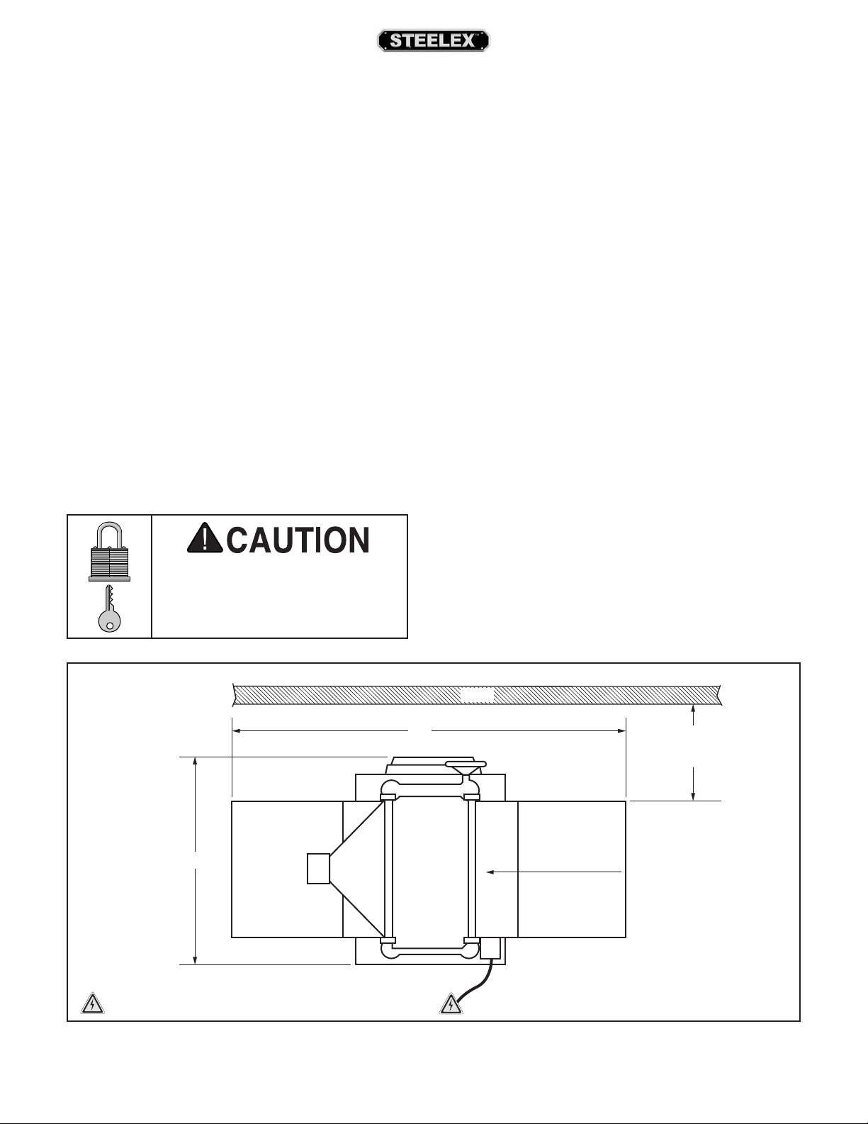
Electrical Installation
Children or untrained people
may be seriously injured by this
machine. Only install in an access
restricted location.
28"
Port
See
out/tagout device, if required.
Lighting
42"
impede the operator must be eliminated.
Wall
Min. 30"
for Maintenance
Feed DirectionDust
= Electrical Connection Illustration Not To Scale
Figure 9. Minimum working clearances.
ST1007/12/14 15" & 20" Planers (Mfd. Since 3/16)
-17-
Page 20
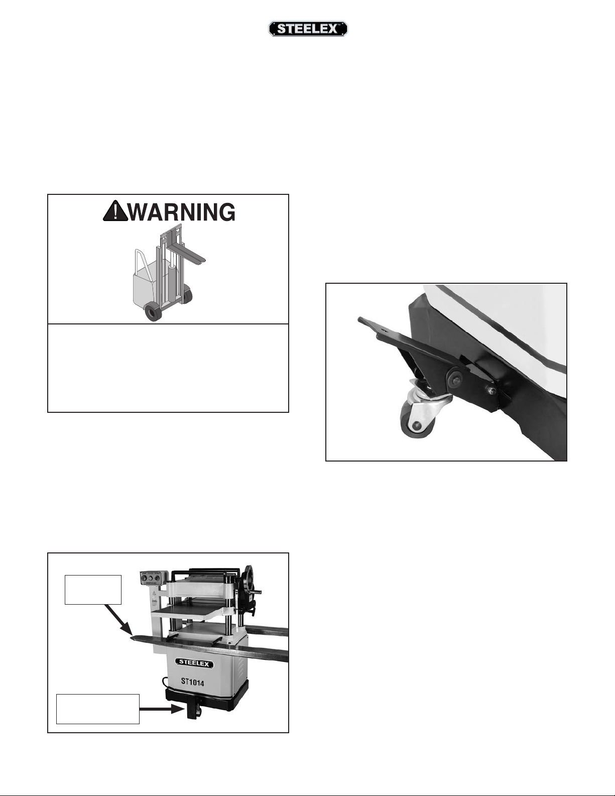
Lifting & Moving
The planer is equipped with four lifting bars that
extend in order to lift and place the planer, as shown
in Figure 10.
2. Remove the pin and hex bolt that are already
mounted in the foot pedal bracket.
3. Align the caster assembly with the mounting
holes in the foot pedal bracket.
The rear wheels and front feet mount to the bottom
of the machine. Therefore, the best time to assemble
these components is while the machine is elevated
safely by the forklift.
HEAVY LIFT!
Straining or crushing injury may occur from
improperly lifting machine or some of its parts.
To reduce this risk, get help from other people
and use a forklift (or other lifting equipment)
rated for weight of this machine.
4. Insert the hex bolt into the hole in the back side
of the caster assembly, and tighten the bolt just
enough for it to be snug without hampering the
pivot action of the caster.
5. Attach the foot pedal to the caster and secure
together by inserting the pin between the two
parts.
6. Lock the caster and pedal (see Figure 11) in
place with the E-clip and washers.
To lift and place machine:
1. Use forklift to lift machine off pallet (see Figure
10).
Tip: When positioning lift forks, place shop rags
or cardboard between forks and cabinet stand to
avoid scratching paint.
Lifting Bar
(1 of 4)
Caster Assembly
Installed
Figure 11. Caster installed.
-18-
Figure 10. Lifting planer with forklift.
ST1007/12/14 15" & 20" Planers (Mfd. Since 3/16)
Page 21
Assembly
The cast-iron extension wings are identical for both
the infeed and the outfeed ends of the table.
To assemble planer:
4. With a helper, match the tapped holes on the
side of the table to the cast iron wings and
lightly secure the wings in place with the (3)
M8-1.25 x 30 hex bolts and the 8mm lock and
flat washers (for the ST1014 use (3) M8-1.25 x 35
hex bolts).
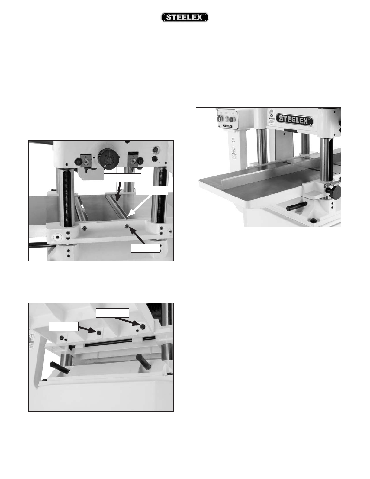
1. Clean the wing, table, wing mating surfaces, and
wipe a thin film of oil on the surfaces.
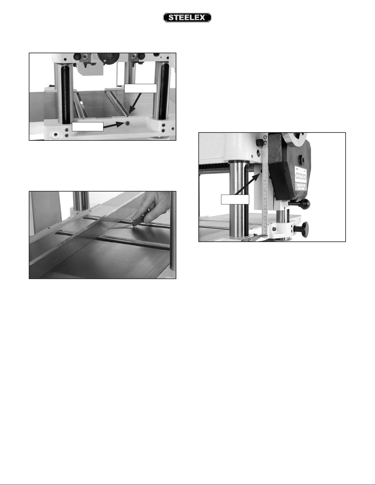
2. Loosen the table-roller set screws and turn the
eccentrics until the table rollers fall below the
table surface. Refer to Figure 12 for locations.
Table Roller
Set Screw
Eccentric
Figure 12. Table roller adjustment locations.
3. Install (2) M8-1.25 x 20 set screws into each
wing. Refer to Figure 13 for location.
Set Screw
Hex Bolt
5. Place a straightedge flat across the table and
across the wings, as shown in Figure 14.
Figure 14. Setting wing height.
6. Adjust the M8-1.25 x 20 set screws so the wings
are flush with the table.
7. Tighten the hex bolts to secure the wings in
place. The top of the wings should now be
completely even with the top of the table, but
double-check to make sure that the wings did
not move during the tightening process.
8. Treat the wing and table top surface with an
anti-rust compound or light machine oil to prevent rust.
Figure 13. Extension wing installed.
ST1007/12/14 15" & 20" Planers (Mfd. Since 3/16)
Note: If this is a first-time setup, DO NOT adjust the
table rollers yet, you will do this adjustment later.
-19-
Page 22
9. Place the bushing on the handwheel shaft and
This machine creates substantial amounts of
dust during operation. Breathing airborne dust
on a regular basis can result in permanent
respiratory illness. Reduce your risk by wearing
a respirator and capturing the dust with a dust
Do not confuse this CFM recommendation with the
rating of the dust collector. To determine the CFM at
the dust port, you must consider these variables: (1)
CFM rating of the dust collector, (2) hose type and
length between the dust collector and the machine,
(3) number of branches or wyes, and (4) amount of
other open lines throughout the system. Explaining
how to calculate these variables is beyond the scope
of this manual. Consult an expert or purchase a good
insert the key into the shaft keyway.
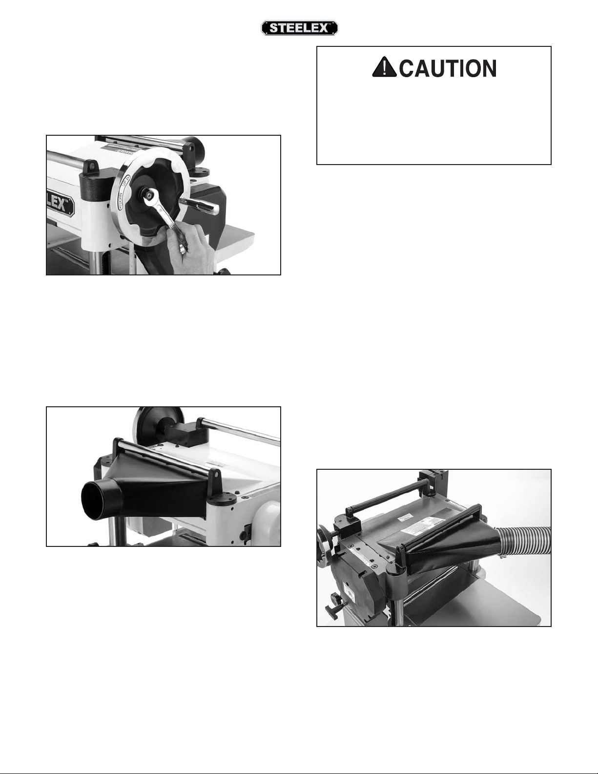
10. Screw the handle into the handwheel, place the
handwheel on the shaft and secure it with the
hex nut and flat washer, as shown in Figure 15.
Figure 15. Handwheel installation.
11. Match the holes in the dust hood to the tapped
holes in the planer casting on the outfeed end
and install the three M8-1.25 x 20 cap screws.
collection system.
Recommended CFM at Dust Port
• ST1007 & ST1012 ......................................... 400 CFM
• ST1014 ............................................................. 625 CFM
12. Secure the top of the dust hood with the M6-1.0
x 12 hex bolts flat and lock washers (see Figure
16).
Figure 16. Dust hood installed.
To connect the machine to a dust collection system,
fit a 4" dust hose (ST1007 & ST1012) or a 5" dust hose
(ST1014) over the dust port, and secure in place with
a hose clamp (see Figure 17). Tug the hose to make
sure it does not come off.
Note: A tight fit is necessary for proper performance.
Figure 17. Dust hose connected to dust port.
-20 -
ST1007/12/14 15" & 20" Planers (Mfd. Since 3/16)
Page 23
18. Loosen the eccentric set screws; as shown in
Figure 18.
Set Screw
Eccentric
Figure 18. Roller set screws.
19. Using a straightedge and wrench, raise the
rollers on their eccentric shafts 0.002" to 0.020"
above the table surface (see Figure 19).
21. Wipe dirt from the gearbox fill plug and remove
it (see Figure 20).
—If the oil runs out, the gearbox is full, and
re-install the plug.
—If the oil does not run out, fill the gearbox
until it does, and re-install the plug.
Note: Replace the gearbox oil after the first 20
hours of operation. This is a normal break-in
procedure.
Fill Plug
Figure 19. Checking roller height.
20. Tighten the eccentric set screws and recheck the
roller height, and re-adjust if required.
Note: For quick and easy table roller setup, consid-
er purchasing a Rotacator. This handy tool allows
you to watch the height of the table rollers you
adjust it, giving you accuracy within 0.001" every
time.
Figure 20. Gearbox fill plug.
ST1007/12/14 15" & 20" Planers (Mfd. Since 3/16)
-21-
Page 24
Test Run
Once assembly is complete, test run the machine to
ensure it is properly connected to power and safety
components are functioning correctly.
If you find an unusual problem during the test run,
immediately stop the machine, disconnect it from
power, and fix the problem
operating the
machine again. The Troubleshooting table in the
SERVICE section of this manual can help.
an improperly set up machine may result in
malfunction or unexpected results that can
Serious injury or death can result from
using this machine BEFORE understanding
its controls and related safety information.
BEFORE
DO NOT operate, or allow others to operate,
machine until the information is understood.
5. Press START button to turn machine ON. Verify
motor starts up and runs smoothly without any
unusual problems or noises.
6. Press STOP button to turn machine OFF.
7. WITHOUT resetting STOP button, try to start
machine by pressing the START button. The
machine should not start.
—If the machine does not start, the STOP
button safety feature is working correctly.
Congratulations! The Test Run is complete.
—If the machine does start (with the STOP
button pushed in), immediately disconnect
power to the machine. The STOP button safety feature is not working correctly and must
be replaced before further using the machine.
Call Tech Support for help.
DO NOT start machine until all preceding setup
instructions have been performed. Operating
lead to serious injury, death, or machine/property damage.
To test run machine:
1. Clear all setup tools and loose objects away from
machine.
2. Push STOP button in.
3. Connect machine to power supply.
4. Twist STOP button clockwise until it springs out
(see Figure 21). This resets the switch so the
machine can start.
After approximately 16 hours of operation,
V-belts will stretch and seat into pulley grooves
and need to be properly tensioned to avoid
severely reducing life of V-belts. Refer to
Tensioning/Replacing V-Belts on Page 36 for
detailed instructions.
Recommended
Adjustments
For your convenience, the adjustments listed below
have been performed at the factory.
However, because of the many variables involved
with shipping, we recommend that you at least verify
the following adjustments to ensure the best possible results from your new machine.
Step-by-step instructions for these adjustments can
be found in the SERVICE section starting on Page
39.
-22-
Figure 21. Resetting the switch.
Factory adjustments that should be verified:
• Check V-belt tension (Page 37).
• Adjusting table height (Page 42).
• Pulley alignment (Page 49).
ST1007/12/14 15" & 20" Planers (Mfd. Since 3/16)
Page 25

OPERATIONS
Eye injuries or respiratory problems can occur
while operating this tool. Wear personal protective equipment to reduce your risk from
these hazards.
Loose hair/clothing could
get caught in machinery
and cause serious personal injury. Keep clothing and
long hair away from moving
machinery.
DO NOT investigate problems or adjust the lathe
while it is running. Wait
until the machine is turne d
OFF, unplugged and all
working parts have come
to a complete stop before
proceeding!
The overview below provides the novice machine
operator with a basic understanding of how the
machine is used during operation, so the machine
controls/components discussed later in this manual
are easier to understand. Due to its generic nature,
this overview is NOT intended to be an instructional
guide.
To complete a typical operation, the operator
does the following:
1. Examines workpiece to make sure it is suitable
for planing.
2. Puts on safety glasses or face shield, a respirator,
and ear protection.
3. Places workpiece on table with flat side down
and correctly adjusts table height for workpiece
thickness and depth of cut.
—If workpiece is bowed, operator surface planes
workpiece on a jointer until one side is flat.
Doing so ensures that it sits solidly on planer
table during operation.
4. When all safety precautions have been taken,
turns planer ON.
5. Stands to one side of planer path to reduce risk
of kickback injuries, then feeds workpiece into
planer until infeed roller grabs it.
Overview
This machine will perform many types of operations
beyond the scope of this manual. Many of these can
be dangerous or deadly if performed incorrectly.
The instructions in this section are written with the
understanding that the operator has the necessary
knowledge and skills to operate this machine. If at
any time you are experiencing difficulties performing
any operation, stop using the machine!
ST1007/12/14 15" & 20" Planers (Mfd. Since 3/16)
Note: Infeed and outfeed rollers control feed rate
of workpiece as it passes through planer. Operator
does not push or pull on workpiece.
—If cut is too deep and bogs down planer, oper-
ator immediately reduces depth of cut.
6. Once workpiece is clear of outfeed roller and
stops moving, operator removes workpiece
from outfeed table and measures workpiece
thickness. If further planing is required, operator
raises table slightly (approximately
of the handwheel), then feeds workpiece into
front of planer again.
7. Operator repeats this process until desired thick-
ness is achieved, then turns machine OFF.
1
⁄4 to 1⁄2 turn
-23-
Page 26

Workpiece Inspection
Wood Types
Some workpieces are not safe to use or may require
modification before they are. Before cutting, inspect
all workpieces for the following:
• Material Type: This machine is only intended
for workpieces of natural wood fiber Attempting
to use workpieces of any other material that
may break apart during operation could lead to
serious personal injury and property damage.
• Foreign Objects: Inspect lumber for defects and
foreign objects (nails, staples, embedded gravel,
etc,). If you have any question about the quality
of your lumber, DO NOT use it. Remember, wood
stacked on a concrete floor can have small pieces of stone or concrete pressed into the surface.
• Large/Loose Knots: Loose knots can become
dislodged during operation. Large knots can
cause kickback and machine damage. Always
use workpieces that do not have large/loose
knots.
• Wet or "Green" Stock: Avoid using wood with a
high water content. Wood with more than 20%
moisture content or wood exposed to excessive
moisture (such as rain or snow), will cut poorly
and cause excessive wear to the machine. Excess
moisture can also hasten rust and corrosion of
the machine and/or individual components.
• Excessive Warping: Workpieces with excessive
cupping, bowing, or twisting are dangerous
to cut because they are unstable and often
unpredictable when being cut. DO NOT use
workpieces with these characteristics!
• Minor Cupping: Workpieces with slight cupping can be safely supported if the cupped side
is facing the table. On the contrary, a workpiece
supported on the bowed side will rock during
operation and could cause severe injury from
kickback.
The species of wood, as well as its condition, greatly
affects the depth of cut the planer can effectively
take with each pass.
The chart in the figure below shows the Janka
Hardness Rating for a number of commonly used
species. The larger the number, the harder the
workpiece, and the less material should be removed
in any one pass for good results.
Note: The Janka Hardness Rating is expressed in
pounds of force required to embed a 0.444" steel ball
into the surface of the wood to a depth equal to half the
ball's diameter.
Janka
Species
Ebony 3220
Red Mahogany 2697
Rosewood 1780
Red Pine 1630
Sugar Maple 1450
White Oak 1360
White Ash 1320
American Beech 1300
Red Oak 1290
Black Walnut 1010
Teak 1000
Black Cherry 950
Cedar 900
Sycamore 770
Douglas Fir 660
Chestnut 540
Hemlock 500
White Pine 420
Basswood 410
Eastern White Pine 380
Balsa 100
Figure 22. Janka Hardness Rating for some
common wood species.
Hardness
-24-
ST1007/12/14 15" & 20" Planers (Mfd. Since 3/16)
Page 27

Planing Tips
Cutting Problems
• Inspect your lumber for twisting or cupping, and
surface one face on a jointer if necessary before
planing workpiece.
• Scrape off all glue when planing glued-up pan-
els. Dried glue can quickly dull knives/inserts.
• DO NOT plane more than one piece at a time.
• Never remove more than the recommended
amount of material on each pass. Only remove
a small amount of material on each pass when
planing wide or dense stock.
• Support the workpiece on both ends. Get assis-
tance from another person if you are planing
long lumber, or use roller stands to support the
workpiece.
• Measure the workpiece thickness with calipers
to get exact results.
• Carefully inspect all stock to make sure it is free
of large knots or foreign objects that may damage your knives/inserts, cause kickback, or be
ejected from the planer.
• When possible, plane equal amounts on each
side of the board to reduce the chance of twisting or cupping.
• Use the entire width of the planer to wear
knives/inserts evenly. With narrow workpieces,
alternate between far left, far right, and the middle of the table. Your knives/inserts will remain
sharp much longer.
• To avoid "chip marks," always plane WITH the
grain direction of the wood. Never plain crossgrain or end-grain.
Below is a list of wood characteristics you may
encounter when planing. The following descriptions
of defects will give you some possible answers to
problems you may encounter while planing different
materials. Possible solutions follow the descriptions.
Chipped Grain
Problem: Usually a result of cutting against the grain,
planing lumber with knots or excessive amount of
cross grain, or using dull knives/inserts.
Note: Some amount of chipping is normal with highly
figured wood.
Solution: Decrease the depth of cut. Reduce the feed
rate. Inspect your lumber and determine if its grain
pattern is causing the problem. If the lumber does
not show substantial crossgrain, inspect your knives/
inserts.
Fuzzy Grain
Problem: Usually caused by surfacing lumber with
too high of a moisture content. Sometimes fuzzy
grain is an unavoidable characteristic of some woods,
such as basswood. Fuzzy grain can also be caused by
dull knives/inserts.
Solution: Check the lumber with a moisture meter. If
moisture is greater than 20%, sticker the lumber and
allow it to dry. Otherwise, inspect the knife/insert
condition.
Snipe
Problem: Occurs when board ends have more mate-
rial removed than the rest of the board. Usually
caused when the workpiece is not properly supported as it goes through the machine. In many cases,
however, a small amount of snipe is inevitable.
• Plane ONLY natural wood fiber. Do not plane
wood composites or other materials that could
break up in the planer and cause operator injury
or damage to planer.
• Always true cupped or warped stock on a jointer
before planing.
ST1007/12/14 15" & 20" Planers (Mfd. Since 3/16)
Solution: Hold workpiece up slightly as it leaves the
outfeed end of the planer. The best way to deal with
snipe is by planing lumber longer than your intended work length and then cutting off the excess after
planing is completed.
-25-
Page 28

Pitch & Glue Build-up
Problem: Glue and resin buildup on the rollers and
cutterhead will cause overheating by decreasing
cutting sharpness while increasing drag in the feed
mechanism. The result can include scorched lumber,
uneven knife/insert marks, and chatter.
Solution: Clean the rollers and cutterhead.
Depth of Cut
Table Movement per Handwheel Revolution
One Full Revolution .........................................................
The depth of cut on a planer means the amount
of material that is removed from the top of the
workpiece as it passes underneath the cutterhead.
1
⁄16"
Chip Marks or Indentations
Problem: Chip indentation or chip bruising is the
result of wood chips not being thrown away from
the cutterhead and out of the machine. Instead they
are carried around the cutterhead, deposited on the
planed surface and crushed by the outfeed roller.
Some of the causes of chip indentation are:
• Wood chips/sawdust not being properly
expelled from the cutterhead.
• The type of lumber being planed. Certain spe-
cies have a tendency to chip bruise.
• A high moisture content (over 20%) or surface
moisture (refer to Page 25).
• Dull knives.
• Excessive depth of cut.
Solution:
The depth of cut is set by adjusting the distance
of the table below the cutterhead. This distance is
the thickness of the workpiece minus the depth of
cut. The planing depth of cut is controlled by using
the table height handwheel on the right side of the
machine. Rotating the handwheel clockwise raises
the table.
Although the correct depth of cut varies according
to wood hardness and workpiece width, we recommend the maximum depth of cut (per pass) be no
1
more than
⁄16". A series of light cuts will give better
end results and put less stress on the planer than
trying to take off too much material in a single pass.
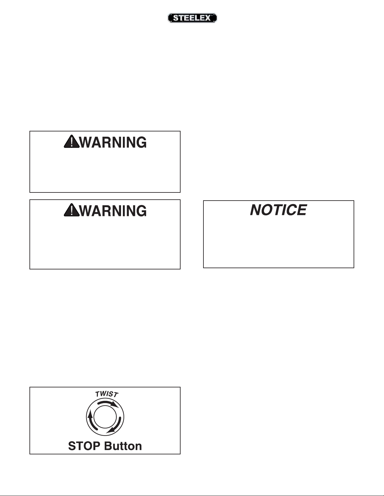
The depth of cut can be referenced directly from the
inch/millimeter scale on the front of the planer, as
shown in Figure 23. The range of material thickness
3
that can be planed is
⁄16"–8".
Note: The scale functions as a general guide only, and is
not intended for low-tolerance, precision results.
• Use a proper dust collection system; adjust chip
deflector in or out as necessary.
• Lumber must be completely dry, preferably kiln-
dried (KD). Air-dried (AD) lumber must be seasoned properly and have no surface moisture.
DO NOT surface partially-air-dried (PAD) lumber.
• Make sure planer knives/inserts are sharp.
• Reduce depth of cut.
Rippled Cut
Problem: Regularly spaced indentations across face
of workpiece are caused by excessive outfeed roller
pressure or excessive feed rate.
Solution: Reduce outfeed roller pressure; reduce
feed rate.
-26-
Table
Height
Handwheel
Depth of Cut
Indicator &
Scale
Figure 23. Depth of cut indicator and scale.
ST1007/12/14 15" & 20" Planers (Mfd. Since 3/16)
Page 29

Bed Roller Height
Bed Roller Height Range .......................... 0.002"–0.020"
The correct height of the bed rollers will vary,
depending on the type of material you intend to
plane. However, as a general rule, keep the bed roller
height within 0.002"–0.020" above the table surface,
as illustrated in Figure 24.
Table
0.002"–0.020"
Tools Needed Qty
Hex Wrench 4mm (ST1007, ST1012) ............................. 1
Hex Wrench 3mm (ST1014) .............................................. 1
Hex Wrench 6mm ................................................................. 1
Rotacator ................................................................................. 1
To adjust bed rollers:
1. DISCONNECT MACHINE FROM POWER!
2. Completely lower table to give yourself enough
room to work.
3. Loosen set screws (see Figure 25) above each
of four roller adjustment cams (there are two on
each side of planer).
Roller
Figure 24. Recommended bed roller height above
the table surface.
When planing rough stock, set the rollers high to
keep the lumber from dragging along the bed. When
planing milled lumber, set the rollers low to help
minimize snipe.
To ensure accurate results and make the adjustment
process quicker and easier, we recommend using a
Rotacator (refer to Page 32) to gauge the bed roller
height from the table surface. If a Rotacator is not
available, a straightedge and feeler gauges can be
used, but care must be taken to achieve accurate
results.
Bed rollers that are not adjusted to the correct
height or out of alignment with each other can
cause poor finishes, inconsistent planing thickness, and other undesirable results.
Set Screws
Adjustment
Cams
Figure 25. Bed roller height controls.
4. Rotate eccentric adjustment cams to raise or
lower bed rollers to desired height above table
surface.
5. Verify both sides of each roller are at the same
height, then re-tighten set screws to secure in
place.
6. Re-check roller heights to make sure they did
not change while being secured.
— If roller heights are not correct, repeat this
procedure until they are.
ST1007/12/14 15" & 20" Planers (Mfd. Since 3/16)
-27-
Page 30

Setting Feed Rate
Adjusting/Replacing
The infeed and outfeed rollers move the workpiece
through the planer while keeping it flat and providing a consistent rate of movement. The speed that
these rollers move the workpiece through the planer
is the feed rate.
Generally, low feed rates are used for dimensioning
passes, while higher feed rates are used for finishing
passes.
Figure 26 illustrates the three different positions of
the feed rate control knob:
• Push knob in to use high feed rate of 30 FPM.
• Pull the knob out to use the low feed rate of 16
FPM.
• Move knob to center position to place gearbox
in neutral.
20 FPM (ST1014)
30 FPM (ST1007/ST1012)
16 FPM
Knives (ST1007)
To reduce risk of shock or
accidental startup, always
disconnect machine from
power before adjustments,
maintenance, or service.
Cutterhead knives are extremely sharp.
Accidental contact with knives can result in
severe cuts. Take great caution whenever working with or around cutterhead knives. Wear
heavy leather gloves to reduce risk of severe
cuts.
To maintain accurate and consistent planing
results, we do not recommend sharpening
knives yourself. Instead, just replace dull knives
or have them professionally sharpened.
Neutral
Figure 26. Feed rate control knob positions.
NOTICE
Only change the feed rate when the planer is
running, but DO NOT attempt to change the
feed rate during any cutting operations or
damage to the gearbox will result.
Setting the height of the knives correctly is crucial
to the proper operation of your planer and is very
important in keeping the knives sharp. If one knife
protrudes higher than the others, it will do the majority of the work, dull much faster, and produce poor
cutting results.
The knife-setting jig that is included with the Model
ST1007 is designed to set the knives 0.059" higher
than the cutterhead surface.
Note: If you need to replace or sharpen a knife, you
can remove the knife from the cutterhead during Step
5 of the following procedure. Thoroughly clean out any
debris from the knife slots before replacing the knives.
Tools Needed Qty
Phillips Screwdriver ............................................................. 1
Open-End Wrench 12, 13mm ....................................1 Ea.
Hex Wrench 3mm ................................................................. 1
Knife-Setting Jig ................................................................... 1
-28-
ST1007/12/14 15" & 20" Planers (Mfd. Since 3/16)
Page 31

The cutterhead for the Model ST1007 ships with both
springs and jack screws for adjusting the knife height
(see Figure 27). Which one you use is a matter of
personal preference. Springs exert upward pressure
from underneath the knives and allow adjustments
to be made very quickly. Jack screws support the
knives from underneath, and by threading the screws
in or out, you can precisely control the knife height.
In both instances, wedge-type gibs and gib bolts lock
the knives in place. Choose whichever method meets
your needs, but understand that the screws and
springs cannot be used together—you must choose
one and remove the other.
To adjust height of knives:
1. DISCONNECT MACHINE FROM POWER!
2. Put on heavy leather gloves to protect your
hands.
3. Remove rear dust hood and top cover to expose
cutterhead.
4. Remove belt cover, then rotate cutterhead pulley to give you good access to one of the knives.
5. Loosen cutterhead gib bolts until knife is completely loose, then position knife-setting jig over
knife so that knife edge is directly under center
pad, as shown in Figure 28.
Center
Pad
Gib
Bolt
Knife
Gauge
Knife
Figure 28. Knife-setting jig correctly positioned
over knife.
6. Springs: Push down on knife gauge until all
legs of the gauge are firmly on the cutterhead
and the knife just touches the centerpad of the
gauge. Then tighten the gib bolts enough to
hold the knife in place.
Loosen
Tighten
Knife
Spring
Gib Bolt
Gib
Jack
Screw
Figure 27. ST1007 cutterhead components (springs
and jack screws both shown).
Jack Screws: Insert hex wrench into jack screws
through access holes in cutterhead (see Figure
29). Rotate jack screws to raise or lower knife
until it barely touches center pad of knife gauge
with all legs of gauge still firmly on cutterhead.
Then snug gib bolts enough to hold knife in
place.
Jack Screw
Access Holes
Figure 29. ST1007 & ST1012 jack screw access hole
in cutterhead.
ST1007/12/14 15" & 20" Planers (Mfd. Since 3/16)
-29-
Page 32

7. Slightly tighten gib bolts, starting at middle and
working your way to ends by alternating left and
right, as illustrated in Figure 30.
5
Figure 30. Gib bolt tightening sequence.
7. Repeat Step 6, tightening gib bolts a little more.
8. Repeat Steps 4–8 for remaining knives.
9. Fully tighten all gib bolts in sequence shown in
Figure 30 for each knife.
3
1
2
4
Rotating/Replacing
Cutterhead Inserts
(ST1012/ST1014)
The helical cutterhead is equipped with indexable
carbide inserts that can be rotated to reveal any one
of their four cutting edges. If one edge of the insert
becomes dull or damaged, simply rotate it 90° to
reveal a fresh cutting edge, as shown in Figure 31.
Uneven tightening or over-tightening the gib
bolts may warp the cutterhead, causing it to
become unbalanced, which will lead to premature knife and bearing wear from vibration.
Figure 31. Insert rotating sequence.
Tools Needed Qty
Phillips Screwdriver #2 ....................................................... 1
Hex Wrench 5mm ................................................................. 1
Torque Wrench ...................................................................... 1
T-20 Torx Bit ............................................................................ 1
To rotate or replace a helical cutterhead insert:
1. DISCONNECT MACHINE FROM POWER!
2. Remove dust hood, top cover, and belt cover.
3. Put on heavy leather gloves to protect your fin-
gers and hands.
The carbide inserts are very sharp and can
quickly cut your hands. ALWAYS use caution
and heavy leather gloves when handling these
parts to reduce the risk of personal injury.
-30-
ST1007/12/14 15" & 20" Planers (Mfd. Since 3/16)
Page 33

4. Remove any sawdust or debris from head of
insert, Torx screw, and surrounding area (see
Figure 32).
Torx Screw
Cutterhead
Insert
Figure 32. Example of cutterhead inserts and Torx
screws (actual machine not shown).
5. Remove Torx screw and insert, then clean all
dust and debris from both parts and pocket they
were removed from.
6. Replace insert so that a fresh cutting edge faces
outward.
— If all four insert cutting edges have been used,
replace insert with a new one. Always position
insert reference dot in same position when
installing a new insert to aid in rotational
sequencing.
7. Lubricate Torx screw threads with a very small
amount of light machine oil, wipe excess off, and
torque screw to 50–55 inch/pounds.
Note: If too much oil is applied to the threads,
excess oil will attempt to squeeze out of the threaded hole and raise insert during installation, bringing it out of height alignment.
Note: Proper cleaning of insert, Torx screw, and
cutterhead pocket is critical to achieving a smooth
finish. Dirt or dust trapped between insert and
cutterhead will raise insert, and make marks on
your workpiece when planing.
Tip: Use low-pressure compressed air or a vacuum
nozzle to clean out cutterhead pocket.
ST1007/12/14 15" & 20" Planers (Mfd. Since 3/16)
-31-
Page 34

ACCESSORIES
The following lathe accessories may be available through your local Woodstock International Inc. Dealer. If you
do not have a dealer in your area, these products are also available through online dealers. Please call or e-mail
Woodstock International Inc. Customer Service to get a current listing of dealers at: 1-800-545-8420 or at sales@
woodstockint.com.
The W1218A Rotacator is a dial indicator on a
magnetic base, designed for quickly and accurately
setting the critical tolerances needed when making
planer adjustments. Perfect for adjusting infeed/
outfeed rollers, pressure bars, chip breakers, and bed
rollers. Also a great setup tool for other machines!
Accurate to 0.001". Indicator rotates 360°.
Figure 33. Model W1218A Rotacator.
The D3379 Carbide Inserts for Spiral Cutterheads
measure 15mm x 15mm x 2.5mm and are sold in a
10-pack.
The W1216A Planer Pal is a knife-setting system
that lets you set planer knives in perfect alignment.
It also allows you to shift nicked knives on 2-1/2" to
4" diameter cutterheads to get a perfect cut to an
accuracy of + or - .002".
Figure 35. Model W1216A Planer Pal.
The W1834 20" Blade Grinder is ideal for sharpen-
ing planer and jointer knives. High-quality cast iron
construction, together with large capacity makes this
grinder an excellent investment.
Figure 34. Carbide insert for Spiral Cutterhead.
-32-
Figure 36. 20" Blade Grinder.
ST1007/12/14 15" & 20" Planers (Mfd. Since 3/16)
Page 35

The D3635 15" Planer Blades fit our Steelex ST1007
planer. Made from high-speed steel, these knives are
sold as a set of 3.
Figure 37. Model D3635 15" Planer Blades.
The Model D2274 5-Roller Stand is great for work
stability and support. It features large diameter, ball
bearing rollers mounted on a sturdy, adjustable pedestal base.
The Model D4042 6" Digital Caliper lets you switch
between decimal and fractional inches and millimeters. Large digital readout makes precision measurements easy with a resolution of 0.0005". Features
include hardened stainless-steel jaws and beam,
thumb roll, lock knob, zero reset button, and an absolute and relative measurement function.
Figure 39. Model D4042 6" Digital Caliper.
Figure 38. Model D2274 5-Roller Stand.
The D4091 7-pc. Woodworking Kit includes a 9"
graduated steel square, 10-1/2" sliding bevel gauge,
rectangular protractor, 10" divider with pencil holder
and pencil, 12" double ended steel ruler, and double
ended scriber.
Figure 40. Model D4091 7-Pc. Woodworking Kit.
ST1007/12/14 15" & 20" Planers (Mfd. Since 3/16)
-33-
Page 36

The D4028 8" Digital Scale provides precise relative
distance measurements between fixed and moving
parts within an 8" and 12" range. Ideal for mounting to woodworking and metalworking machines
for table height adjustments, cutter heights, depth
adjustments and more. Resolution is 0.01mm and
maximum measuring speed is 1.5m/s. Features
inches and millimeters conversion button, plus and
minus preset buttons and zero setting on button.
Each Digital Scale includes an extra long life battery.
Mounting screws are not included.
The Model D2273 Single Roller Stand features
large-diameter ball bearings for smooth operation
with a variety of processing and work-support applications. Heavy pedestal base is stable and secure.
Figure 42. Model D2273 Single Roller Stand.
Figure 41. Model D4028 8" Digital Scale.
-34-
ST1007/12/14 15" & 20" Planers (Mfd. Since 3/16)
Page 37

MAINTENANCE
To reduce risk of shock or
accidental startup, always
disconnect machine from
power before adjustments,
Schedule
For optimum performance from your machine, follow
this maintenance schedule and refer to any specific
instructions given in this section.
maintenance, or service.
General
Regular periodic maintenance on your STEELEX
Model ST1007/ST1012/ST1014 will ensure its optimum performance. Make a habit of inspecting your
machine each time you use it.
Check for the following conditions and repair or
replace when necessary:
• Loose mounting bolts.
• Worn switch.
• Worn or damaged cords and plugs.
• Damaged V-belt.
• Any other condition that could hamper the safe
operation of this machine.
Daily Check:
• Clean unpainted cast iron parts of the table
• Lubricate feed rollers
®
Weekly Check:
• Clean cutterhead
• Lubricate the four columns
• Change gear box oil (should be performed after
the first 20 hours when planer is new).
Monthly Check:
• Inspect V-belt tension, damage, or wear
• Clean/vacuum dust buildup from inside cabinet
and off motor
• Lubricate worm gear
• Lubricate chain
• Lubricate drive chain
Cleaning/Protecting
Vacuum excess wood chips and sawdust, and wipe
off the remaining dust with a dry cloth. If any resin
has built up, use a resin dissolving cleaner to remove
it.
ST1007/12/14 15" & 20" Planers (Mfd. Since 3/16)
Protect the unpainted cast iron table by wiping it
clean after every use—this ensures moisture from
wood dust does not remain on bare metal surfaces.
Keep the table rust-free with regular applications of a
high-quality metal protectant.
-35-
Page 38

Basic Adjustment Tools
Optional Adjustment
We have provided a jig to make the knife setting process easy and quick. Please refer to Figure 43 for jig
component identification while assembling.
To assemble the knife setting jig:
1. Snap one of the E-clips over the notch on one
end of the knife setting rod.
2. Slide the aluminum knife setting jig saddles
onto the rod.
3. Snap the other E-clip on the other end of the
knife setting rod.
Tools
To make the setup process easier and more accurate,
many woodworkers purchase optional aftermarket
products like the Rotacator® and the Planer Pal®.
• Rotacator — A rotating dial indicator on a magnetic base. This handy device allows you to set
your table within 0.001" from being parallel with
the cutterhead. The Rotacator is indispensable
when adjusting the chip breaker, table rollers,
feed rollers, and measuring table roller protrusion shown in Figure 44.
Figure 43. Provided knife setting gauge.
Figure 44. Rotacator measuring table roller
protrusion.
• Planer Pal — Using powerful neodymium magnets, Planer Pal (see Figure 45) holds knives in
place while freeing both hands to tighten the
gib. Place one of these jigs on each end of the
cutterhead, and you can set the knives in perfect
alignment every time.
-36-
Figure 45. Planer Pal jigs holding knives for superior
adjustment.
ST1007/12/14 15" & 20" Planers (Mfd. Since 3/16)
Page 39

Lubrication
Since all bearings are sealed and permanently
lubricated, leave them alone until they need to be
replaced. Do not lubricate them.
The Model ST1007/ST1012/ST1014 does need
lubrication in other places.
• Columns and Leadscrews: Lubricate columns
weekly with light oil, and lubricate the four
leadscrews once a month with general purpose
grease.
• Worm Gear: Inspect the worm gear monthly
and lubricate when needed. The worm gear box
will need to be removed to perform the inspection (see Figure 46).
Grease
Grease
Oil
Fill Plug
Drain
Plug
Figure 47. Gear box lubrication.
• Drive Chain: Inspect and lubricate the drive
chain monthly. Check the sprockets, the chain,
and the master links during inspection. Use a
general purpose grease to lubricate the chain.
• Feed Rollers: Lubricate feed rollers daily before
start-up. Figure 48 shows the lubrication points
for the feed rollers. These are screws that have
holes drilled through them to allow oiling. Make
sure that dust is not trapped in these screws and
apply two drops of light oil in each to penetrate
the bearings. Do not lubricate more than this or
the excess will end up on the floor.
Figure 46. Worm gear lubrication.
• Chain: Inspect the table height adjustment
chain monthly and lubricate as needed. Use
high quality chain lubricant for best results.
• Gear Box: Drain the gear box after the first 20
hours of operation. Figure 47 shows the gear
box drain and fill plugs. Refill with 80-90W gear
oil. The oil level should reach the top of the filler
plug port. After the initial change, inspect fluid
levels periodically and change yearly. If your
planer receives heavy use, change the gear oil
more frequently.
ST1007/12/14 15" & 20" Planers (Mfd. Since 3/16)
Oil
Oil
Figure 48. Feed roller lubrication.
-37-
Page 40

Tensioning/Replacing
V-Belts
Tools Needed Qty
Phillips Screwdriver ............................................................. 1
Open-End Wrench 19mm.................................................. 1
To tension/replace V-belts:
After approximately 16 hours of operation,
V-belts will stretch and seat into pulley grooves
and need to be properly tensioned to avoid
severely reducing life of V-belts.
Three V-belts transfer power from the motor to the
cutterhead, and then to the infeed and outfeed rollers with the use of the drive chain system. To ensure
efficient transfer of power to these systems, make
sure the V-belts are always properly tensioned and in
good condition.
If the V-belts are worn, cracked, or damaged, replace
them. Always replace the V-belts with a matched set
of three, or belt tension may not be even among the
belts, causing premature belt failure.
V-belts and pulleys will be hot after operation.
Allow them to cool before handling.
1. DISCONNECT MACHINE FROM POWER!
2. Remove V-belt cover from left side of machine to
expose belts, as shown in Figure 49.
Note: A collection of black belt dust at the bottom
of the belt cover is normal during the life of the
belts.
Cutterhead
Pulley
V-Belts
Motor
Pulley
Figure 49. Belt cover removed to expose V-belts
and pulleys.
3. Remove front cabinet cover to access motor, as
shown in Figure 50.
Motor Mount
Hex Nuts
Figure 50. Front cabinet cover removed to access
motor.
-38-
ST1007/12/14 15" & 20" Planers (Mfd. Since 3/16)
Page 41

4. If V-belts need to be replaced, raise motor to
release belt tension (see next step for instructions), roll them off pulleys, then replace with a
matched set of 3.
5. To adjust V-belt tension, loosen both top motor
mount hex nuts (see Figure 50 on Page 38),
then adjust bottom hex nuts to raise or lower
motor.
Anti-Kickback Pawls
The Model ST1007/ST1012/ST1014 features anti-kickback pawls (shown in Figure 52) as an important safety feature. These safety devices allow the
workpiece to enter the planer without affecting
the proper operation, but are designed to stop the
workpiece from coming back out of the entrance in
the event of a kickback.
Note: V-belts are correctly tensioned when there is
approximately
sure is applied to them midway between pulleys,
as illustrated in Figure 51.
3
⁄4" deflection when moderate pres-
Cutterhead
Pulley
Approximately
3
⁄4" Deflection
Motor
Pulley
Figure 51. Belt deflection when V-belts are correctly
tensioned.
6. After V-belts are correctly tensioned, tighten top
motor mount hex nuts, then re-install cabinet
cover and belt cover.
The anti-kickback pawls should be frequently checked
to ensure that they swing free and easy. Do not try to
lubricate the pawls. Lubrication may cause dust to
build-up, which will restrict movement.
Proper operation of the anti-kickback pawls is
essential to the safe operation of the planer. If
they aren’t working properly, they will not protect you if a kickback occurs.
Anti-Kickback Pawls
ST1007/12/14 15" & 20" Planers (Mfd. Since 3/16)
Figure 52. Anti-kickback pawls.
-39-
Page 42

SERVICE
Troubleshooting
The following troubleshooting tables cover common problems that may occur with this machine.
If you need replacement parts or additional troubleshooting help, contact our Technical Support.
Note: Before contacting Tech Support, find the machine serial number and manufacture date, and if
available, your original purchase receipt. This information is required to properly assist you.
Motor & Electrical
PROBLEM POSSIBLE CAUSE CORRECTIVE ACTION
Machine does not
start or a breaker
trips.
Machine stalls or is
underpowered.
1. Emergency stop button depressed/at fault.
2. Incorrect power supply voltage or circuit size.
3. Motor overheated, causing thermal overload to
trip.
4. Power supply circuit breaker tripped or fuse
blown.
5. Motor wires connected incorrectly.
6. Wiring open/has high resistance.
7. Power switch at fault.
8. Centrifugal switch at fault.
9. Start capacitor at fault.
10. Thermal overload relay at fault.
11. Contactor not energized/has poor contacts.
12. Motor at fault.
1. Machine undersized for task.
2. Workpiece not suitable for machine.
3. Motor overheated, causing thermal overload to
trip.
4. Belt(s) slipping; oil/grease on belt(s).
5. Dull knives/inserts.
6. Dust collection problem causing internal components to clog up with shavings.
7. Motor wired incorrectly.
8. Centrifugal switch at fault.
9. Run capacitor at fault.
10. Pulley slipping on shaft.
1. Rotate button head to reset. Replace.
2. Ensure correct power supply voltage and circuit size.
3. Allow motor to cool, reset overload if necessary, and
reduce depth of cut. Contact Tech Support if relay
frequently trips.
4. Ensure circuit is sized correctly and free of shorts. Reset
circuit breaker or replace fuse.
5. Correct motor wiring connections.
6. Check/fix broken, disconnected, or corroded wires.
7. Replace switch.
8. Adjust/replace centrifugal switch if available.
9. Test/replace.
10. Replace.
11. Test all legs for power/replace.
12. Test/repair/replace.
1. Reduce feed rate/depth of cut.
2. Only cut wood/ensure moisture is below 20%.
3. Allow motor to cool, reset overload if necessary, and
reduce depth of cut. Contact Tech Support if relay
frequently trips.
4. Clean/tension/replace belt(s); align pulleys (Page 38).
5. Sharpen/replace knives, or replace inserts (Page 28).
6. Clear blockages in dust chute/ducting, ensure dust collector is operating efficiently.
7. Wire motor correctly.
8. Adjust/replace centrifugal switch if available.
9. Test/repair/replace.
10. Tighten loose pulley; replace pulley/shaft if damaged.
Machine has
vibration or noisy
operation.
-40-
11. Contactor not energized/has poor contacts.
12. Motor bearings at fault.
1. Motor or component loose.
2. V-belt(s) worn or loose; belts slapping cover.
3. Pulley loose.
4. Bed rollers protruding unevenly.
5. Plastic chip deflector hitting knives.
6. Motor fan rubbing on fan cover.
7. Knives/gibs at fault.
8. Motor bearings at fault.
9. Cutterhead bearings at fault.
11. Test all legs for power/replace.
12. Test/repair/replace.
1. Inspect/tighten loose bolts/nuts; replace damaged components.
2. Tension/replace belts as a matched set (Page 38).
3. Re-align/replace shaft, pulley set screw, and key.
4. Adjust bed rollers (Page 27).
5. Adjust chip deflector; replace if necessary.
6. Fix/replace fan cover; replace loose/damaged fan.
7. Sharpen/replace knives; set knife alignment/height correctly (Page 28).
8. Test by rotating shaft; rotational grinding/loose shaft
requires bearing replacement.
9. Replace bearing(s).
ST1007/12/14 15" & 20" Planers (Mfd. Since 3/16)
Page 43

Machine Operation
PROBLEM POSSIBLE CAUSE CORRECTIVE ACTION
Excessive snipe
(gouge in end
of board that is
uneven with rest
of cut).
Note: A small
amount of snipe is
inevitable with all
types of planers.
The key is minimizing it as much as
possible.
Workpiece stops/
slows in middle
of cut.
Chipping (consistent pattern).
Chipping/indentation in workpiece
surface (inconsistent pattern).
Fuzzy grain. 1. Wood may have high moisture content or surface
Long lines or ridges that run along
length of board.
1. One or both of bed rollers are set too high.
2. Outfeed extension slopes down or is not level
with main table.
3. Chipbreaker/pressure bar set too low.
4. Workpiece is not supported as it leaves planer.
5. Some snipe is inevitable.
1. Taking too heavy of a cut.
2. One or both of bed rollers are set too low or too
high.
3. Chipbreaker or pressure bar set too low.
4. Feed rollers set too low or too high.
5. Pitch and glue build up on planer components.
1. Knots or conflicting grain direction in wood.
2. Taking too deep of a cut.
3. Feeding workpiece too fast.
4. Mis-adjusted chipbreaker.
5. Nicked or chipped knife/insert.
1. Chips aren't being properly expelled from
cutterhead.
2. Chip breaker not set correctly.
wetness.
2. Dull knives/inserts.
1. Nicked or chipped knife/inserts. 1. Replace knives (Page 28) or have them professionally
1. Lower bed rollers (Page 27).
2. Shim outfeed extension wing level with main table.
3. Raise height of chipbreaker or pressure bar (Page 42).
4. Hold workpiece up slightly as it leaves outfeed end of
planer.
5. Plane lumber longer than your intended workpiece
length, then cut off excess after planing complete.
1. Take a lighter cut.
2. Lower/raise bed rollers (Page 27).
3. Raise height of chipbreaker or pressure bar (Page 42).
4. Lower/raise feed rollers (Page 42).
5. Clean internal cutterhead components with a pitch/
resin dissolving solvent.
1. Inspect workpiece for knots and grain direction; only
use clean stock, and cut WITH the grain.
2. Take a smaller depth of cut. (Reduce cutting depth when
planing hard woods.)
3. Slow down feed rate.
4. Adjust both sides of chipbreaker to correct height.
5. Replace affected knife (Page 28), or have it sharpened;
rotate/replace insert (Page 30).
1. Use a proper dust collection system.
2. Correctly adjust chip breaker (Page 42).
1. Check moisture content is below 20% and allow to dry if
moisture is too high.
2. Replace knives (Page 28) or have them professionally
sharpened; rotate/replace inserts (Page 30).
sharpened; rotate/replace inserts (Page 30).
Uneven cutting`
marks, wavy surface, or chatter
marks across face
of board.
Glossy surface. 1. Knives/inserts are dull.
If workpiece twists
in machine.
1. Feeding workpiece too fast.
2. Chipbreaker or pressure bar set unevenly or not
low enough.
3. Knives not installed evenly/inserts not properly
installed.
4. Worn cutterhead bearings.
2. Feeding workpiece too slow.
3. Cutting depth too shallow.
1. Pressure bar set unevenly.
2. Feed rollers not parallel with table.
ST1007/12/14 15" & 20" Planers (Mfd. Since 3/16)
1. Slow down feed rate.
2. Adjust height of chipbreaker or pressure bar (Page 42).
3. Adjust knives with knife gauge (Page 28); remove
inserts, properly clean mounting pocket and re-install
(Page 30).
4. Replace cutterhead bearings.
1. Replace knives (Page 28) or have them professionally
sharpened; rotate/replace inserts (Page 30).
2. Increase feed rate.
3. Increase depth of cut.
1. Adjust height of pressure bar (Page 42).
2. Adjust feed rollers (Page 42).
-41-
Page 44

Adjusting Feed
Rollers, Chip Breaker
& Pressure Bar
It is essential that the feed rollers, chip breaker, and
pressure bar (see Figure 53) are set at the correct
distance below the cutterhead knives/inserts at BDC
(bottom dead center) to ensure that the workpiece
moves through the planer evenly and the correct
distance from the cutterhead knives/inserts.
Chip
Breaker
A & B
Figure 53. Planer component recommended
clearances. Illustration is not to scale.
(Bottom Dead Center)
Infeed
Roller
BDC
Outfeed
Roller
Pressure
Bar
C
D
Using a Rotacator
Tools Needed Qty
Phillip's Screwdriver #2 ...................................................... 1
Hex Wrench 3mm ................................................................. 1
Open-End Wrench or Socket 10mm.............................. 1
Rotacator (see Page 36) .................................................... 1
To use a rotacator:
1. DISCONNECT MACHINE FROM POWER!
2. Make sure knives are set to correct height (refer
to Adjusting/Replacing Knives on Page 28
for detailed instructions). If machine is spiral
cutterhead, make sure all inserts are properly installed (refer to Rotating/Replacing
Cutterhead Inserts on Page 30 for detailed
instructions).
3. Lower table at least 4" below head casting, then
lock it in place.
4. Remove dust hood, top cover, belt cover, and
drive chain cover.
5. Lower bed rollers below table surface (refer
to Bed Roller Height on Page 27 for detailed
instructions).
To ensure accurate results and make the adjustment
process quicker and easier, we recommend using a
Rotacator for these adjustments (refer to Page 36).
If a Rotacator is not available, a 6-foot-long 2x4 cut
into two even sized pieces and a feeler gauge set can
be used, but care must be taken when jointing the
wood to achieve accurate results.
Distance Below Knife/Insert at BDC (Figure 53)
A. Infeed Roller ........................................................ 0.040"
B. Chip Breaker ....................................................... 0.040"
C. Pressure Bar.........................................................0.040"
D. Outfeed Roller .................................................... 0.020"
Note: Only Model ST1014 has a pressure bar.
-42-
ST1007/12/14 15" & 20" Planers (Mfd. Since 3/16)
Page 45

6. Rotate the cutterhead with the V-belt pulley so
one of the knives is at BDC as shown in Figure
54.
7. Use your Rotacator to find bottom dead center
(BDC) of any knife/insert edge by slowly rocking cutterhead pulley back and forth, then set
Rotacator dial to "0" (see Figure 54).
10. Repeat Steps 8–9 on left-hand side of infeed
roller.
11. Re-check both sides of infeed roller and, if necessary, make further adjustments until infeed
roller height from side-to-side is 0.040" below
BDC of cutterhead knife/insert, then re-tighten
both jam nuts.
8. Keeping Rotacator dial at "0", position it under
right-hand side of infeed roller (see Figure 54)
and find BDC of a serrated edge.
Figure 54. Finding BDC of cutterhead.
9. Loosen jam nuts and use set screws on each side
of feed roller (see Figure 55) to adjust height of
infeed roller bushing block until Rotacator dial
shows 0.040", which is the recommended distance for infeed roller below cutterhead.
12. Keeping same "0" reference on Rotacator dial
from Step 7, repeat Steps 8–9 for outfeed roller, but adjust it until it is 0.020" below BDC of
cutterhead knife/insert.
13. Using same "0" reference on Rotacator dial from
Step 7, perform similar steps as described above
to adjust height of chip breaker to its recommended specification given at beginning of this
subsection. The adjustment controls are shown
in Figure 56.
Jam Nut and
Adjustment
Set Screw
Jam Nut
Adjustment Stud
Figure 55. Feed roller height adjustment.
ST1007/12/14 15" & 20" Planers (Mfd. Since 3/16)
Figure 56. Chip breaker height adjustment.
-43-
Page 46

14. Repeat Step 12 for pressure bar height adjust-
ment. The adjustment controls are shown in
Figure 57.
15. Re-install belt cover, top cover, drive chain cover,
and dust hood.
Adjustment Jam Nut
& Set Screw
Figure 57. Example of adjusting the pressure bar
height.
3. DISCONNECT MACHINE FROM POWER!
4. Lower bed rollers below table surface (refer
to Bed Roller Height on Page 27 for detailed
instructions).
5. Place wood blocks along sides of table, as illustrated in Figure 58.
Using Wood Blocks
Tools Needed Qty
Phillips Screwdriver #2 ....................................................... 1
Hex Wrench 3mm ................................................................. 1
Open-End Wrench or Socket 10mm.............................. 1
2x4 6' Long ............................................................................. 1
Feeler Gauge Set .................................................................. 1
To use wood blocks: To use wood blocks:
1. Build wood blocks by cutting a straight 6-foot-
long 2x4 in half.
Note: Having the wood blocks at an even height is
critical to the accuracy of your overall adjustments.
For best results, make the 2x4 square with a jointer
and table saw before cutting it in half.
2. Make sure knives are set to correct height (refer
to Adjusting/Replacing Knives on Page 28 for
detailed instructions).
Figure 58. Gauge boards installed.
6. Remove dust hood, top cover, belt cover, and
drive chain cover.
7. Raise table until wood blocks get close to
cutterhead.
8. Use belt to rotate cutterhead and continue
raising table until blocks just barely touch
cutterhead knife/insert at its lowest point of
rotation (BDC).
9. Lock table in place. Upward pressure of wood
blocks will be holding infeed and outfeed rollers,
chip breaker, and pressure bar at same level as
knife/insert at BDC.
-44-
ST1007/12/14 15" & 20" Planers (Mfd. Since 3/16)
Page 47

10. Loosen jam nuts and set screws on each side of
infeed roller (see Figure 59).
11. Using a feeler gauge, adjust set screw so it is
0.040" from roller bushing block (see Figure 59),
then tighten jam nut. Repeat on other side of
infeed roller.
Roller Bushing
Block
15. Repeat Steps 13–14 for pressure bar height
adjustment, but adjust the gap to 0.040" (see
Figure 61).
Jam Nut &
Set Screw
Insert Feeler
Gauge Here
Insert Feeler
Gauge Here
Jam Nut &
Set Screw
Figure 59. Feeler gauge location for adjusting roller
height using wood blocks.
12. Repeat Steps 10–11 with outfeed roller, only
adjust the gaps to 0.020".
13. Loosen jam nuts and set screws on each side of
chip breaker (see Figure 60).
14. Using a feeler gauge, adjust set screw so it is
0.040" from cross bar (see Figure 60), then tight-
en jam nut. Repeat on other side of chip breaker.
Jam Nut &
Set Screw
Figure 61. Feeler gauge location for adjuting
pressure bar height when using wood blocks.
16. Re-install belt cover, top cover, drive chain cover,
and dust hood.
To re-adjust bed roller height:
1. Use a straightedge and feeler gauge (see Figure
62) to check roller height, and re-adjust as
required between 0.0020" and 0.020".
Insert Feeler
Gauge Here
Cross Bar
Figure 60. Feeler gauge location for adjusting chip
breaker height using wood blocks.
ST1007/12/14 15" & 20" Planers (Mfd. Since 3/16)
Figure 62. Setting table roller height.
-45-
Page 48

Adjusting Roller
Tools Needed Qty
Hex Wrench 6mm ................................................................. 1
Spring Tension
The infeed and outfeed rollers keep the workpiece
moving through the planer. There are springs that
exert downward pressure on the rollers while still
allowing them to raise with an uneven workpiece
surface. Proper roller spring tension is crucial to keep
the workpiece moving through the planer during
operation.
Roller spring tension will vary depending upon the
type of wood you are planing. When adjusting the
roller spring tension keep the following in mind:
• If you are planing milled lumber with a relatively
consistent surface, use less spring tension.
• If you are planing rough lumber with inconsistent surfaces, use greater spring tension to keep
the stock moving through the planer.
• If the workpiece consistently stops feeding
during operation, the roller spring tension may
need to be increased.
To adjust roller spring tension:
1. DISCONNECT MACHINE FROM POWER!
2. Rotate tension screws clockwise to increase
tension, and counterclockwise to decrease tension until they protrude to the values shown in
Figure 63.
Note: The rear-right spring typically requires less
tension because of forces applied from the feed
drive system. The values shown in Figure 63 are
a starting point for further adjustment using trial
and error.
1
⁄8"
5
⁄16"
Figure 63. Roller spring tension adjustment screws.
-46-
ST1007/12/14 15" & 20" Planers (Mfd. Since 3/16)
Page 49

Positioning Chip
Adjusting Table
Deflector
When properly distanced from the cutterhead, the
chip deflector directs the chips into the dust hood,
and keeps them from falling onto the outfeed roller
and being pressed into the workpiece.
1
Chip Deflector Gap Setting ............................................
Tools Needed Qty
Phillips Screwdriver #2 ....................................................... 1
Fine Ruler or Calipers .......................................................... 1
To adjust chip deflector gap:
1. DISCONNECT MACHINE FROM POWER!
2. Remove dust hood, top cover, and belt cover.
3. Use cutterhead pulley to rotate cutterhead until
a knife/insert reaches closest distance to chip
deflector (see Figure 64), then measure distance between knife/insert and chip deflector.
⁄4"
Parallelism
Tools Needed Qty
Phillips Screwdriver #2 ....................................................... 1
Hex Wrench 6mm ................................................................. 1
The table has been pre-set at the factory, but it is a
good idea to check any machine thoroughly before
use.
There are two directions you should be concerned
about. When checking/adjusting the table, the table
should be parallel with the head casting from frontto-back, and the table should be parallel with the
cutterhead body from side-to-side.
To adjust table parallelism:
1. MAKE SURE MACHINE IS UNPLUGGED!
2. Use the plans shown in Figure 65 to make a
wooden gauge block.
Chip
Deflector
Figure 64. Chip deflector.
4. If distance measured in Step 3 is not equal to
1
⁄4", then loosen flange screws that secure chip
deflector and adjust gap to
5. Re-tighten flange screws, then replace belt
cover, top cover, and dust hood.
Bolts
1
⁄4".
Figure 65. Gauge block plans.
3. Place the block on one end of the table, directly
under the cutterhead body. Raise the table up
so the block only touches the cutterhead body
(keep knives rotated out of the way for this step).
4. Without moving the table, slide the block of
wood to the other end of the cutterhead. If the
block of wood will not fit, or if the block is below
the cutterhead body, measure this gap with
a feeler gauge. If the difference is more than
0.002", then the table needs to be adjusted from
left to right.
ST1007/12/14 15" & 20" Planers (Mfd. Since 3/16)
-47-
Page 50

5. Place the block under the front of the head cast-
ing, to either side of the depth limiter tab. Raise
the table up so the block barely touches the
head casting as shown in Figure 66.
Figure 66. Block position.
6. Remove the block and place it between the
middle-rear of the head casting and the table.
If there is a gap or it will not fit under the head
casting, measure the difference with a feeler
gauge. If this measurement is more than 0.002",
then the table needs to be adjusted from front
to back.
To adjust table more than 0.016":
1. Remove the side cabinet plate.
2. On the underside of the table there is a chain
drive and five sprockets as shown in Figure
67. The four sprockets in the corners control
the movement of the table columns. The fifth
sprocket is the idler sprocket that controls the
chain tension. Loosen the two bolts on the idler
sprocket bracket (see Figure 67) to loosen the
chain so that each sprocket can be rotated on its
own. Make sure to hold the chain away from the
sprocket while you adjust it.
Idler Sprocket Bracket
7. There are two methods to adjust the table on
the Model ST1007/ST1012/ST1014. The first is
for adjustments smaller than 0.016" and the second is for adjustments larger than 0.016".
Figure 67. Chain drive system.
3. Moving the sprockets clockwise lowers the table
and moving them counterclockwise raises the
table. Each tooth on the corner sprockets equals
0.016" of vertical movement when the cogs are
turned (See illustration in Figure 68). Make sure,
as you adjust each sprocket, that you count the
number of teeth that pass a fixed point.
Figure 68. Sprocket ratio.
-48-
ST1007/12/14 15" & 20" Planers (Mfd. Since 3/16)
Page 51

To adjust table less than 0.016":
1. Use the table mounting screws shown in Figure
69. Loosen the screws and lift/lower the table
until the table and the cutterhead body are
parallel with each other and the table is parallel
with the head casting from front to back. This
may require some trial and error.
Calibrating Table
Height Scale
Although correctly set at the factory, the table height
scale can be adjusted for accuracy if it becomes necessar y.
Tools Needed ..................................................................... Qty
Hex Wrench 4mm ................................................................. 1
Scrap Piece of Stock ............................................................ 1
Calipers..................................................................................... 1
Table Mounting
Set Screws
Figure 69. Table mounting screws.
2. Adjust each column on both sides until the table
is properly set. While adjusting the columns,
tighten each screw after each step to ensure
accurate results.
3. After you have the table adjusted to within
0.016" from front-to-back and from side-to-side,
tighten the chain so all of the slack is removed.
4. Now follow the next instructions for adjusting
the table when it is less than 0.016" from its
proper position.
To reposition scale:
1. Plane a scrap piece of stock until it is flat and of
even thickness along its length.
Note: Turn board over between each pass.
2. Use calipers to measure board thickness board
thickness and table height scale reading should
be identical.
— If there is a discrepancy between board thick-
ness and reading on table height scale, loosen
both screws shown in Figure 70, adjust scale
in relation to pointer, then re-tighten screws.
Screws
NOTICE
DO NOT let chain fall off sprockets. It can
be very difficult to return chain to its proper
location on sprockets without changing table
adjustments.
ST1007/12/14 15" & 20" Planers (Mfd. Since 3/16)
Scale
& Pointer
Figure 70. Location of table height scale.
-49-
Page 52

Aligning Pulleys
Proper pulley alignment prevents premature V-belt
wear and unnecessary load on the motor. It also
ensures efficient and effective transfer of power. The
pulleys are properly aligned when they are parallel
and in the same plane as each other.
Tools Needed Qty
Straightedge 3' ...................................................................... 1
Hex Wrench 6mm ................................................................. 1
Open-End Wrench or Socket 13mm.............................. 1
To check/re-align pulleys:
1. DISCONNECT MACHINE FROM POWER!
2. Remove both cabinet covers and belt cover,
then use straightedge to check pulley alignment, as shown in Figure 71.
— If pulleys are not parallel, loosen four motor
mount hex nuts (see Figure 72), shift motor
on its mount until pulleys are parallel, then
re-tighten motor mount hex nuts.
Figure 72. Location of motor mount hex nuts.
— If pulleys are not in same plane, loosen cap
screw or hex bolt that secures pulley to shaft,
adjust pulleys in or out until they are in plane,
then re-tighten cap screws.
Figure 71. Checking pulley alignment.
3. Re-check pulleys and repeat Step 2 if necessary.
4. Once pulleys are properly aligned, re-tighten all
fasteners, then replace belt cover and cabinet
covers.
-50-
ST1007/12/14 15" & 20" Planers (Mfd. Since 3/16)
Page 53

ST1007 & ST1012 Electrical Components
Start Button
Control
Box
Power Lamp
Figure 73. ST1007 & ST1012 control panel.
Start
Capacitor
Stop Button
Run
Capacitor
Figure 74. ST1007 & ST1012 capacitors.
Motor
Contactor
Motor
Capacitors
Inside
Motor Thermal
Relay
Figure 75. ST1007 & ST1012 magnetic switch assembly.
ST1007/12/14 15" & 20" Planers (Mfd. Since 3/16)
-51-
Page 54

Hot
Ground
Control Box
Ground
ST1007 Wiring Diagram
CONTROL PANEL
(from Behind)
START
POWER
STOP
G
Hot
240
VAC
6-20 Plug
240V
A1
1L1 5L3 13NO
3L2
NHD C-09D
ContactorThermal Overload Relay
2T1 6T3
4T2
14NO
A2
NHD NTH-21
21
17
20
18
R
O
MAGNETIC
SWITCH ASSY
Ground
-52-
98
97
2T1 6T34T2
96 95
Run
Capacitor
20MFD
450VAC
Start
Capacitor
200MFD
250VAC
MOTOR (240V, Single-Phase)
ST1007/12/14 15" & 20" Planers (Mfd. Since 3/16)
Page 55

Hot
Ground
Control Box
Ground
ST1012 Wiring Diagram
CONTROL PANEL
(from Behind)
START
POWER
STOP
G
Hot
240
VAC
6-20 Plug
240V
A1
1L1 5L3 13NO
3L2
NHD C-09D
ContactorThermal Overload Relay
2T1 6T3
4T2
14NO
A2
NHD NTH-21
21
17
20
18
R
O
MAGNETIC
SWITCH ASSY
Ground
98
97
96 95
2T1 6T34T2
ST1007/12/14 15" & 20" Planers (Mfd. Since 3/16)
Run
Capacitor
40MFD
450VAC
Start
Capacitor
250MFD
250VAC
MOTOR (240V, Single-Phase)
-53-
Page 56

ST1014 Electrical Components
Figure 76. Motor junction box.
Figure 77. Capacitors.
Start
Figure 78. ST1014 control panel (viewed from
Power
behind).
Stop
Figure 79. ST1014 magnetic switch assembly.
-54-
ST1007/12/14 15" & 20" Planers (Mfd. Since 3/16)
Page 57

Control Box
Ground
240 VAC
L6-30 PLUG
Ground
Gn
Rd
A1
ST1014 Wiring Diagram
CONTROL PANEL (viewed from behind)
COLOR KEY
BLACK
WHITE
GREEN
RED
BLUE
G
Bk
Wt
Gn
Rd
Bl
Rd
Gn
POWER
Bk
Wt
Gn
Gn
STOP
Rd
Rd
Rd
Rd
Bk
Rd
Rd
Hot
Gn
X
Wt
Bk
Y
Hot
START
Wt
Rd
Bl
Rd
Gn
Bl
Wt
Rd
Bl
Bk
Gn
Wt
Wt
Bk
Rd
Rd
Bk
Bl
Rd
1L1 5L3 13NO
3L2
17
NHD C-35D
ContactorThermal Overload Relay
2T1 6T3
4T2
18
14NO
GROUND
A2
Rd
NHD NTH-32
26
32
28
31
30
98
97
2T1 6T34T2
Bk
96 95
R
O
Wt
Rd
Rd
Gn
Bk
Wt
240V
MOTOR
Bk
Wt
Gn
Ground
Bk
Bk
Wt
Wt
Rd
Rd
Start
Capacitor
300MFD
300VAC
Run
Capacitor
60MFD
450VAC
ST1007/12/14 15" & 20" Planers (Mfd. Since 3/16)
-55-
Page 58

ST1007/ST1012 PARTS
ST1007/ST1012 Main Breakdown
60
59
58
30-7
30-1
30-2
62
30-8
30-4
44
64
45
46
63
30-10
30-3
30-5
66
65
30-9
30-6
55
56
30
26
27
44
45
27
81
82
83
43
77
37
41
42
50
78
51
79
53
54
80
36
35
35
36
38
39
52
76
57
14
73
70
71
69
68
67
72-3
72
25
72-1
75
72-2
74
72-4
61
14
4
5
7
2
8
49
10
11
16
47
21
22
24
20
48
14
1
19
18
17
23
3
6
9
15
12
-56-
13
ST1007/12/14 15" & 20" Planers (Mfd. Since 3/16)
Page 59

ST1007/ST1012 Main Parts List
30 XST1007030 MOTOR 3HP 240V 1-PH
30-1 XST1007030-1 MOTOR FAN COVER
30-2 XST1007030-2 MOTOR FAN
30-3 XST1007030-3 CAPACITOR COVER
30-4 XST1007030-4 R CAPACITOR 20M 450V
30-5 XST1007030-5 S CAPACITOR 200M 250V
30-6 XST1007030-6 MOTOR JUNCTION BOX
30-7 XST1007030-7 BALL BEARING 6204ZZ
30-8 XST1007030-8 BALL BEARING 6203ZZ
30-9 XST1007030-9 CENTRIFUGAL SWITCH 16MM 3450 RPM
30-10 XST1007030-10 CONTACT PLATE 16MM
30 XST1012030 MOTOR 3HP 240V 1-PH
30-1 XST1012030-1 MOTOR FAN COVER
30-2 XST1012030-2 MOTOR FAN
30-3 XST1012030-3 CAPACITOR COVER
30-4 XST1012030-4 R CAPACITOR 40M 450V
30-5 XST1012030-5 S CAPACITOR 250M 300V
30-6 XST1012030-6 MOTOR JUNCTION BOX
30-7 XST1012030-7 BALL BEARING 6204ZZ
30-8 XST1012030-8 BALL BEARING 6203ZZ
30-9 XST1012030-9 CENTRIFUGAL SWITCH 16MM 3450 RPM
30-10 XST1012030-10 CONTACT PLATE 16MM
REF PART # DESCRIPTION REF PART # DESCRIPTION
1 XST1007001 RUBBER FOOT 49 XST1007049 HEX NUT M10-1.5
2 XST1007002 RELIEF BUSHING 50 XST1007050 BUSHING
3 XST1007003 UNIVERSAL WHEEL 51 XST1007051 MOTOR PLATE PIVOT SHAFT
4 XST1007004 HEX NUT M8-1.25 52 XST1007052 FLAT WASHER 10MM
5 XST1007005 FLAT WASHER 8MM 53 XST1007053 HEX NUT M10-1.5
6 XST1007006 HEX BOLT M8-1.25 X 65 54 XST1007054 HEX BOLT M10-1.5 X 75
7 XST1007007 REAR WHEEL SLEEVE 55 XST1007055 SET SCREW M8-1.25 X 12
8 XST1007008 EXT RETAINING RING 9MM 56 XST1007056 KEY 5 X 5 X 30
9 XST1007009 FLAT WASHER 12MM 57 XST1007057 HEX BOLT M8-1.25 X 20
10 XST1007010 SHAFT 12MM 58 XST1007058 HEX BOLT M6-1 X 16
11 XST1007011 FOOT PEDAL 59 XST1007059 STRAIN RELIEF
12 XST1007012 HEX NUT M8-1.25 60 XST1007060 CONTROL BOX
13 XST1007013 HEX BOLT M8-1.25 X 100 61 XST1007061 CONTROL BOX PEDESTAL
14 XST1007014 FLAT WASHER 8MM 62 XST1007062 TAP SCREW #10 X 3/8
15 XST1007015 HEX BOLT M8-1.25 X 50 63 XST1007063 CONTROL PANEL
16 XST1007016 FOOT PEDAL BRACKET 64 XST1007064 EMERGENCY STOP BUTTON
17 XST1007017 INT RETAINING RING 35MM 65 XST1007065 POWER LAMP
18 XST1007018 BALL BEARING 6202ZZ 66 XST1007066 ON BUTTON
19 XST1007019 LOCKING WHEEL 67 XST1007067 HEX NUT M5-.8
20 XST1007020 LOCKING WHEEL SLEEVE 68 XST1007068 FLAT WASHER 5MM
21 XST1007021 LOCK NUT M12-1.75 69 XST1007069 SWITCH PLATE
22 XST1007022 FLAT WASHER 12MM 70 XST1007070 HEX BOLT M6-1 X 10
23 XST1007023 LOCK NUT M12-1.75 71 XST1007071 FLAT WASHER 6MM
24 XST1007024 FOOT PEDAL CASTER BASE 72 XST1007072 MAGNETIC SWITCH ASSEMBLY
25 XST1007025 HEX BOLT M8-1.25 X 45 72-1 XST1007072-1 CONTACTOR NHD C-09D 230V
26 XST1007026 HEX NUT M8-1.25 72-2 XST1007072-2 OL RELAY NHD NTH-21 17-21A
27 XST1007027 FLAT WASHER 8MM 72-3 XST1007072-3 REAR MAG SW. COVER
35 XST1007035 FLAT WASHER 12MM 72-4 XST1007072-4 FRONT MAG SW. COVER
36 XST1007036 HEX NUT M12-1.75 73 XST1007073 PHLP HD SCR M5-.8 X 25
37 XST1007037 ADJUST BOLT 74 XST1007074 POWER CORD 12G 3W 72" 6-20P
38 XST1007038 SET SCREW M6-1 X 8 75 XST1007075 MOTOR CORD
39 XST1007039 COLLAR 76 XST1007076 SWITCH CORD
41 XST1007041 PLATE CONNECTING ROD 77 XST1007077 HEX WRENCH 2.5MM
42 XST1007042 SET SCREW M6-1 X 12 78 XST1007078 HEX WRENCH 3MM
43 XST1007043 MOTOR PLATE 79 XST1007079 HEX WRENCH 4MM
44 XST1007044 PHLP HD SCR M6-1 X 20 80 XST1007080 HEX WRENCH 6MM
45 XST1007045 COVER 81 XST1007081 WRENCH 8 X 10MM OPEN-ENDS
46 XST1007046 STAND 82 XST1007082 WRENCH 14 X 17MM OPEN-ENDS
47 XST1007047 HEX BOLT M10-1.5 X 55 83 XST1007083 WRENCH 17 X 19MM OPEN-ENDS
48 XST1007048 FLAT WASHER 10MM
ST1007 3HP Motor
ST1007/12/14 15" & 20" Planers (Mfd. Since 3/16)
ST1012 3HP Motor
-57-
Page 60

ST1007/ST1012 Headstock Parts Diagram
120
123
104
121
117
123
122
116
119
126
199
197
198
128
194
195
177
124
196
125
193
132
178
114
140
173
186
115
118
141
168
170
171
179
113
139
167
114
162
142
166
161
111
165
130
169
185
160
150
112
113
135
163
159
157
149
107
109
133
173
182
110
136
158
106
164
170
171
134
155
146
103
108
154
114
138
137
156
169
148
102
101
105
132
165
151
153
167
168
ST1007 Parts
147
200-1
200-2
129
127
131
152
145
144
143
ST1012 Parts
-58-
181
165
174
176
175
180
167
172
191
192
189
190
188
183
187
182
149
183
184
150
200
ST1007/12/14 15" & 20" Planers (Mfd. Since 3/16)
Page 61

ST1007/ST1012 Headstock Parts List
REF PART # DESCRIPTION REF PART # DESCRIPTION
101 XST1007101 HANDLE 152 XST1007152 FLAT WASHER 6MM
102 XST1007102 HEX NUT M12-1.75 153 XST1007153 OUTFEED ROLLER SPROCKET
103 XST1007103 FLAT WASHER 12MM 154 XST1007154 DEPTH SCALE
104 XST1007104 FLAT WASHER 8MM 155 XST1007155 FLAT WASHER 6MM
105 XST1007105 HANDWHEEL 156 XST1007156 PHLP HD SCR M6-1 X 12
106 XST1007106 COLLAR 157 XST1007157 DEPTH SCALE POINTER
107 XST1007107 INT RETAINING RING 32MM 158 XST1007158 FLAT WASHER 6MM
108 XST1007108 BALL BEARING 6201ZZ 159 XST1007159 PHLP HD SCR M6-1 X 12
109 XST1007109 KEY 4 X 4 X 20 160 XST1007160 CUT LIMIT PLATE
110 XST1007110 WORM GEAR 161 XST1007161 PHLP HD SCR M6-1 X 8
111 XST1007111 WORM HOUSING 162 XST1007162 HEAD CASTING
112 XST1007112 CAP SCREW M5-.8 X 55 163 XST1007163 OUTFEED ROLLER
113 XST1007113 RETURN ROLLER 164 XST1007164 KEY 5 X 5 X 16
114 XST1007114 RETURN ROLLER BRACKET 165 XST1007165 COMPRESSION SPRING
115 XST1007115 CAP SCREW M8-1.25 X 14 166 XST1007166 OIL PORT
116 XST1007116 BELT COVER 167 XST1007167 BUSHING BLOCK
117 XST1007117 FEMALE KNOB M8-1.25 168 XST1007168 BUSHING BLOCK PLATE
118 XST1007118 FLANGE BOLT M6-1 X 12 169 XST1007169 HEX BOLT M8-1.25 X 16
119 XST1007119 DUST HOOD 170 XST1007170 SET SCREW M5-.8 X 12
120 XST1007120 CAP SCREW M8-1.25 X 20 171 XST1007171 HEX NUT M5-.8
121 XST1007121 HEX BOLT M6-1 X 10 172 XST1007172 CHIP BREAKER ADJUSTMENT ROD
122 XST1007122 HEX NUT M6-1 173 XST1007173 SET SCREW M6-1 X 20
123 XST1007123 FLAT WASHER 6MM 174 XST1007174 CHIP BREAKER
124 XST1007124 UPPER COVER 175 XST1007175 SET SCREW M6-1 X 18
125 XST1007125 FLANGE BOLT M6-1 X 12 176 XST1007176 HEX NUT M6-1
126 XST1007126 FOAM GASKET 177 XST1007177 STANDOFF HEX
127 XST1007127 GEAR BOX COVER 178 XST1007178 COLUMN LOCK ROD
128 XST1007128 V-BELT MX60 179 XST1007179 EXT RETAINING RING 12MM
129 XST1007129 CAP SCREW M8-1.25 X 45 180 XST1007180 LOCK WASHER 12MM
130 XST1007130 ROLL PIN 6 X 20 181 XST1007181 HEX NUT M12-1.75
131 XST1007131 GEARBOX COVER SHIELD 182 XST1007182 E-CLIP 15MM
132 XST1007132 FLANGE BOLT M6-1 X 10 183 XST1007183 SPACER
133 XST1007133 IDLE BRACKET 184 XST1007184 ANTI-KICKBACK FINGER
134 XST1007134 IDLE BRACKET SHAFT 185 XST1007185 ANTI-KICKBACK SHAFT
135 XST1007135 COLLAR 186 XST1007186 SET SCREW M8-1.25 X 16
136 XST1007136 EXTENSION SPRING 187 XST1007187 HEX BOLT M6-1 X 16
137 XST1007137 SPRING RETAINER 188 XST1007188 FLAT WASHER 6MM
138 XST1007138 CAP SCREW M6-1 X 8 189 XST1007189 SPROCKET
139 XST1007139 CHIP DEFLECTOR PLATE 190 XST1007190 CHAIN 06B-1 X 63
140 XST1007140 FLANGE BOLT M6-1 X 12 191 XST1007191 KEY 5 X 5 X 16
141 XST1007141 PLATE SPRING 192 XST1007192 INFEED ROLLER
142 XST1007142 FLANGE BOLT M6-1 X 12 193 XST1007193 FLAT WASHER 6MM
143 XST1007143 PLANER KNIVES 15" X 1" X 1/8" 3-PK 194 XST1007194 HEX BOLT M6-1 X 12
144 XST1007144 GIB (ST1007) 195 XST1007195 CUTTERHEAD PULLEY
145 XST1007145 GIB SCREW (ST1007) 196 XST1007196 MOTOR PULLEY
146 XST1007146 JACK SCREW NUT M5-.8 (ST1007) 197 XST1007197 COLLAR
147 XST1007147 JACK SCREW M5-.8 X 16 (ST1007) 198 XST1007198 HEX BOLT M8-1.25 X 20
148 XST1007148 CUTTERHEAD 15" 3-KNIFE (ST1007) 199 XST1007199 BELT GUARD
149 XST1007149 KEY 8 X 8 X 36 200 XST1012200 CUT TERHEAD 15" HELICAL (ST1012)
150 XST1007150 BALL BEARING 6205ZZ 200-1 XST1012200-1 FLAT HD TORX T20 M6-1 X 15 (ST1012)
151 XST1007151 HEX BOLT M6-1 X 16 200-2 XST1012200-2 CARBIDE INSERT 15 X 15 X 2.5 (ST1012)
ST1007/12/14 15" & 20" Planers (Mfd. Since 3/16)
-59-
Page 62

ST1007/ST1012 Gearbox Diagram & Parts List
220
201
242
241
240
234
209
211
202
205
233
232
229
228
231
230
227
221
222
243
209
210
217
208
226
225
213
239
235
238
215
212
219
213
223
216
224
204
203
206
207
214
218
237
236
REF PART # DESCRIPTION REF PART # DESCRIPTION
201 XST1007201 GEARBOX COVER 223 XST1007223 COMPRESSION SPRING
202 XST1007202 HEX BOLT M6-1 X 25 224 XST1007224 STEEL BALL 4MM
203 XST1007203 SPROCKET 225 XST1007225 COMBO GEAR
204 XST1007204 FLAT WASHER 8MM 226 XST1007226 KEY 5 X 5 X 50
205 XST1007205 HEX BOLT M8-1.25 X 16 227 XST1007227 GEARBOX GASKET
206 XST1007206 CHAIN 06B-1 X 51 228 XST1007228 GEARBOX
207 XST1007207 ROUND KNOB M8-1.25 229 XST1007229 HEX BOLT M8-1.25 X 50
208 XST1007208 GEARED SHAFT 230 XST1007230 OIL DRAIN PLUG
209 XST1007209 BALL BEARING 6201-OPEN 231 XST1007231 FLANGE COVER
210 XST1007210 GEAR 232 XST1007232 CAP SCREW M5-.8 X 12
211 XST1007211 KEY 5 X 5 X 14 233 XST1007233 OIL SEAL 25 X 40 X 10
212 XST1007212 GEARED SHAFT 234 XST1007234 PIN 5 X 10
213 XST1007213 BALL BEARING 6201-OPEN 235 XST1007235 SHIFTER FORK
214 XST1007214 GEAR 236 XST1007236 SHIFTER SHAFT
215 XST1007215 KEY 5 X 5 X 10 237 XST1007237 O-RING 16 X 2.4
216 XST1007216 OIL SEAL 25 X 32 X 7 238 XST1007238 FLANGE BOLT M6-1 X 12
217 XST1007217 GEAR SHAFT 239 XST1007239 KEY 5 X 5 X 16
218 XST1007218 BALL BEARING 6204ZZ 240 XST1007240 BALL BEARING 6204-OPEN
219 XST1007219 EXT RETAINING RING 20MM 241 XST1007241 GEAR
220 XST1007220 BALL BEARING 6201ZZ 242 XST1007242 SET SCREW M6-1 X 20
221 XST1007221 PHLP HD SCR M6-1 X 8 243 XST1007243 FILL PLUG
222 XST1007222 FLAT WASHER 6MM
-60-
ST1007/12/14 15" & 20" Planers (Mfd. Since 3/16)
Page 63

ST1007/ST1012 Lower Table Diagram & Parts List
318
316
313
305
315
327
310
333
306
320
307
319
313
321
305
320
322
323
305
324
329
309
301
311
326
325
308
302
328
314
313
317
312
320
303
329
304
303
304
REF PART # DESCRIPTION REF PART # DESCRIPTION
301 XST1007301 CHAIN 12.7A X 134 316 XST1007316 GEAR
302 XST1007302 HEX BOLT M12-.175 X 45 317 XST1007317 KEY 4 X 4 X 12
303 XST1007303 FLAT WASHER 12MM 318 XST1007318 EXT RETAINING RING 12MM
304 XST1007304 LIFTING BAR 319 XST1007319 SPROCKET
305 XST1007305 COLUMN 320 XST1007320 KEY 5 X 5 X 16
306 XST1007306 BALL BEARING 6302ZZ 321 XST1007321 FLAT WASHER 10MM
307 XST1007307 INT RETAINING RING 42MM 322 XST1007322 HEX NUT M10-1.5
308 XST1007308 DRIVE COLUMN 323 XST1007323 CHAIN TENSION BRACKET
309 XST1007309 SPROCKET 324 XST1007324 EXT RETAINING RING 15MM
310 XST1007310 SET SCREW M10-1.5 X 12 325 XST1007325 FLAT WASHER 8MM
311 XST1007311 LEADSCREW 326 XST1007326 HEX BOLT M8-1.25 X 20
312 XST1007312 DRIVE LEADSCREW 327 XST1007327 INT RETAINING RING 40MM
313 XST1007313 LEADSCREW NUT 328 XST1007328 HEX NUT M12-1.75
314 XST1007314 CAP SCREW M6-1 X 20 329 XST1007329 EXT RETAINING RING 15MM
315 XST1007315 BUSHING 333 XST1007333 BASE
ST1007/12/14 15" & 20" Planers (Mfd. Since 3/16)
-61-
Page 64

ST1007/ST1012 Upper Table Diagram & Parts List
417
417-1
417-2
410
413
416
412
417-3
411
409
408
409
413
414
415
408
407
411
401
410
405
406
404
REF PART # DESCRIPTION REF PART # DESCRIPTION
401 XST1007401 SET SCREW M8-1.25 X 20 412 XST1007412 SET SCREW M6-1 X 16
404 XST1007404 HEX BOLT M8-1.25 X 30 413 XST1007413 ECCENTRIC SHAFT
405 XST1007405 FLAT WASHER 8MM 414 XST1007414 BALL BEARING 6203ZZ
406 XST1007406 LOCK WASHER 8MM 415 XST1007415 BED ROLLER
407 XST1007407 EXTENSION WING 416 XST1007416 MAIN TABLE
408 XST1007408 KNOB M12-1.75 FEMALE 417 XST1007417 KNIFE-SETTING JIG (ST1007)
409 XST1007409 WEDGE DOG 417-1 XST1007417-1 EXT RETAINING RING 8MM (ST1007)
410 XST1007410 GIB 417-2 XST1007417-2 KNIFE-SETTING JIG FOOT (ST1007)
411 XST1007411 LOCK BAR 417-3 XST1007417-3 KNIFE-SETTING JIG SHAFT (ST1007)
-62-
ST1007/12/14 15" & 20" Planers (Mfd. Since 3/16)
Page 65

ST007/ST1012 Label Placement
ST1007 Machine Labels A
(02/23/16)
• 1:1 Scale (Labels are
actual size)
• Labels must be made of
chemical-resistant material
***IMPORTANT***: This label must have individual letters/numbers. Do not print with clear background.
(02/17/16)
• 1:1 Scale (Labels are
actual size)
• Labels must be made of
chemical-resistant material
COPYRIGHT © WOODSTOCK INTERNATIONAL, INC.
FOR SHOP FOX MACHINES ONLY! DO NOT REPRODUCE OR CHANGE THIS ARTWORK
WITHOUT WRITTEN APPROVAL!
Woodstock will not accept labels changed without
approval. If artwork changes are required, contact us immediately at
manuals@woodstockint.com.
READ and UNDERSTAND
MANUAL to avoid serious
injury! If a manual is not
available, DO NOT use
machine! Instead, go to
www.shopfox.biz or call
(
360) 734-3482.
WARNING!
WARNING
ACCIDENTAL
INJURY HAZARD!
Disconnect power
supply before
adjustments, setup
or maintenance!
(02/17/16)
• 1:1 Scale (Labels are
actual size)
• Labels must be made of
chemical-resistant material
COLOR CODES
PANTONE 151 C or RAL 2005WARNING
PANTONE YELLOW C
CAUTION
Only shift gearbox when
planer is running.
Neutral
30 FPM
16 FPM
READ and UNDERSTAND
MANUAL to avoid serious
injury! If a manual is not
available, DO NOT use
machine! Instead, go to
www.shopfox.biz or call
(
360) 734-3482.
WARNING!
WARNING
ACCIDENTAL
INJURY HAZARD!
Disconnect power
supply before
adjustments, setup
or maintenance!
WARNING!
EYE/EAR/LUNG
INJURY HAZARD!
Always wear safety
glasses, ear protection,
and respirator when
using this machine.
ST1007 Machine Labels B
(02/17/16)
• 1:1 Scale (Labels are
actual size)
• Labels must be made of
chemical-resistant material
COLOR CODES
READ and UNDERSTAND
MANUAL to avoid serious
injury! If a manual is not
available, DO NOT use
machine! Instead, go to
www.shopfox.biz or call
(
360) 734-3482.
WARNING!
WARNING
ACCIDENTAL
INJURY HAZARD!
Disconnect power
supply before
adjustments, setup
or maintenance!
WARNING!
EYE/EAR/LUNG
INJURY HAZARD!
Always wear safety
glasses, ear protection,
and respirator when
using this machine.
• 1:1 Scale (Labels are
actual size)
• Labels must be made of
chemical-resistant material
COPYRIGHT © WOODSTOCK INTERNATIONAL, INC.
FOR SHOP FOX MACHINES ONLY! DO NOT REPRODUCE OR CHANGE THIS ARTWORK
WITHOUT WRITTEN APPROVAL!
Woodstock will not accept labels changed without
approval. If artwork changes are required, contact us immediately at
manuals@woodstockint.com.
READ and UNDERSTAND
MANUAL to avoid serious
injury! If a manual is not
available, DO NOT use
machine! Instead, go to
www.shopfox.biz or call
(
360) 734-3482.
WARNING!
• 1:1 Scale (Labels are
actual size)
• Labels must be made of
chemical-resistant material
COPYRIGHT © WOODSTOCK INTERNATIONAL, INC.
FOR SHOP FOX MACHINES ONLY! DO NOT REPRODUCE OR CHANGE THIS ARTWORK
WITHOUT WRITTEN APPROVAL!
Woodstock will not accept labels changed without
approval. If artwork changes are required, contact us immediately at
manuals@woodstockint.com.
)
734-3482.
WARNING!
ST1007 Machine Labels C
(02/22/16)
• 1:1 Scale (Labels are
actual size)
• Labels must be made of
chemical-resistant material
(02/17/16)
• Labels must be made of
chemical-resistant material
COPYRIGHT © WOODSTOCK INTERNATIONAL, INC.
FOR SHOP FOX MACHINES ONLY! DO NOT REPRODUCE OR CHANGE THIS ARTWORK
WITHOUT WRITTEN APPROVAL!
Woodstock will not accept labels changed without
approval. If artwork changes are required, contact us immediately at
manuals@woodstockint.com.
COLOR CODES
PANTONE 151 C or RAL 2005
WARNING
PANTONE YELLOW C
CAUTION
Only shift gearbox when
planer is running.
Neutral
30 FPM
16 FPM
READ and UNDERSTAND
MANUAL to avoid serious
injury! If a manual is not
available, DO NOT use
machine! Instead, go to
www.shopfox.biz or call
(
360) 734-3482.
WARNING!
WARNING
ACCIDENTAL
INJURY HAZARD!
Disconnect power
supply before
adjustments, setup
or maintenance!
WARNING!
EYE/EAR/LUNG
INJURY HAZARD!
Always wear safety
glasses, ear protection,
and respirator when
using this machine.
ST1007
ST1014 Machine Labels A
(03/10/16)
• 1:1 Scale (Labels are
actual size)
• Labels must be made of
chemical-resistant material
COLOR CODES
DANGER
PANTONE 485 C or RAL 3001
PANTONE 151 C or RAL 2005
WARNING
***IMPORTANT***: This label must have individual letters/numbers. Do not print with clear background.
MODEL ST1014
20" PLANER WITH HELICAL CUTTERHEAD
1. Read and understand owner’s manual before
operating.
2. Always wear approved eye protection, hearing
protection, and respirator.
3. Disconnect power before setup, adjustments, or
service.
4. Keep all guards in place and in proper operating
condition.
5. Be aware of "kickback" hazards and how to
prevent them.
6. Plug power cord into grounded outlet only.
7. Make sure machine is correctly set up, adjusted, and
rests securely on flat, level ground before operating.
8. Do not wear loose clothing, gloves, jewelry, or other
items that can get entangled. Tie back long hair and
roll up sleeves.
9. Do not plane boards with cracks, loose knots, or any
other defects.
10. Never make adjustments to the table during cutting
operation.
Specifications
Cutterhead: Helical w/Indexable Inserts
Number of Inserts: 100
Insert Size: 15 x 15 x 2.5mm (Curved)
Replacement Inserts: D4655
Weight: 771 lbs.
Date
Serial Number
Manufactured for Woodstock in China
To reduce the risk of serious injury when using this machine:
11. Do not reach into the cutting area while machine is
running.
12. Stand clear of board ends while planing.
13. Only operate in dry environment free of rain or
dampness.
14. Do not operate under the influence of drugs or
alchohol.
15. Prevent unauthorized use by children or untrained
users; restrict access or disable machine when
unattended.
WARNING!
ST1012
ST1014 Machine Labels A
(03/10/16)
• 1:1 Scale (Labels are
actual size)
• Labels must be made of
chemical-resistant material
COLOR CODES
DANGER
PANTONE 485 C or RAL 3001
PANTONE 151 C or RAL 2005
WARNING
***IMPORTANT***: This label must have individual letters/numbers. Do not print with clear background.
MODEL ST1014
20" PLANER WITH HELICAL CUTTERHEAD
1. Read and understand owner’s manual before
operating.
2. Always wear approved eye protection, hearing
protection, and respirator.
3. Disconnect power before setup, adjustments, or
service.
4. Keep all guards in place and in proper operating
condition.
5. Be aware of "kickback" hazards and how to
prevent them.
6. Plug power cord into grounded outlet only.
7. Make sure machine is correctly set up, adjusted, and
rests securely on flat, level ground before operating.
8. Do not wear loose clothing, gloves, jewelry, or other
items that can get entangled. Tie back long hair and
roll up sleeves.
9. Do not plane boards with cracks, loose knots, or any
other defects.
10. Never make adjustments to the table during cutting
operation.
Specifications
Cutterhead: Helical w/Indexable Inserts
Number of Inserts: 100
Insert Size: 15 x 15 x 2.5mm (Curved)
Replacement Inserts: D4655
Weight: 771 lbs.
Date
Serial Number
Manufactured for Woodstock in China
To reduce the risk of serious injury when using this machine:
11. Do not reach into the cutting area while machine is
running.
12. Stand clear of board ends while planing.
13. Only operate in dry environment free of rain or
dampness.
14. Do not operate under the influence of drugs or
alchohol.
15. Prevent unauthorized use by children or untrained
users; restrict access or disable machine when
unattended.
WARNING!
REF PART # DESCRIPTION REF PART # DESCRIPTION
Safety labels warn about machine hazards and ways to prevent injury. The owner of this machine MUST
maintain the original location and readability of the labels on the machine. If any label is removed
or becomes unreadable, REPLACE that label before using the machine again. Contact Woodstock
International, Inc. at (360) 734-3482 or www.shopfoxtools.com to order new labels.
508
501
STOP
WARNING!
READ and UNDERSTAND
MANUAL to avoid serious
injury! If a manual is not
available, DO NOT use
machine! Instead, go to
www.shopfox.biz or call
(
360) 734-3482.
WARNING!
EYE/EAR/LUNG
INJURY HAZARD!
Always wear safety
glasses, ear protection,
and respirator when
using this machine.
510
POWER
509
START
Specifications
Motor: 3 HP, 240V, 1-Ph, 60 Hz
Full-Load Current: 15A
Maximum Depth of Cut: 1/8"
Minimum Stock Thickness: 3/16"
Minimum Stock Length: 8"
Maximum Cutting Height: 8"
Maximum Cutting Width: 15"
Feed Rates: 16 & 30 FPM
Replacement Knives: D3635
Do not open this cover while machine
is connected to power or is running.
Disconnect power before servicing.
Failure to comply will result in serious
personal injury.
Cutterhead Speed: 4800 RPM
Cutterhead: 3" Dia., 3-Knife
Knife Size: 15" x 1" x 1/8"
Weight: 640 Lbs.
Mfd. for Woodstock in China
Manufactured for Woodstock in China
WARNING!
To reduce the risk of serious injury when using this machine:
1. Read & understand owner’s manual before
operating.
2. Always wear approved eye and hearing protection
and respirator.
3. Disconnect power before setup, adjustments, or
service.
Date
Date
4. Keep all guards in place and in proper operating
condition.
Serial Number
S/N
5. Be aware of "kickback" hazards and how to
prevent them.
503
MODEL ST1007
15" PLANER WITH MOBILE BASE
WARNING!
6. Plug power cord into grounded outlet only.
7. Make sure machine is correctly set up, adjusted, and
rests securely on flat, level ground before operating.
8. Do not wear loose clothing, gloves, jewelry, or other
items that can get entangled. Tie back long hair and
roll up sleeves.
9. Do not plane boards with cracks, loose knots, or any
other defects.
10. Never make adjustments to the table during cutting
operation.
11. Do not reach into the cutting area while machine is
running.
12. Stand clear of board ends while planing.
13. Only operate in dry environment free of rain or
dampness.
14. Do not operate under the influence of drugs or
alchohol.
15. Prevent unauthorized use by children or untrained
users; restrict access or disable machine when
unattended.
Do not open this cover while machine
is connected to power or is running.
Disconnect power before servicing.
Failure to comply will result in serious
personal injury.
WARNING
ACCIDENTAL
INJURY HAZARD!
Disconnect power
supply before
adjustments, setup
or maintenance!
Only shift gearbox when
planer is running.
WARNING!
511
502V2
505
30 FPM
504
Neutral
16 FPM
503
507
501 XST1007501 EYE/EAR/LUNG HAZARD LABEL 507 XST1007507 STEELEX LOGO PLATE
502V2 XST1007502V2 MACHINE ID LABEL W/CSA (ST1007) V2.01.17 508 XST1007508 READ MANUAL LABEL
502V2 XST1012502V2 MACHINE ID LABEL W/CSA (ST1012) V2.01.17 509 XST1007509 ELECTRICITY LABEL
503 XST1007503 DO NOT OPEN COVER LABEL 510 XST1007510 CONTROL PANEL LABEL
504 XST1007504 DISCONNECT POWER LABEL 511 XST1007511 TOUCH-UP PAINT, STEELEX TAN
505 XST1007505 SHIFT GEARBOX LABEL 512 XST1007512 PINSTRIPE TAPE
506 XST1007506 MODEL NUMBER LABEL (ST1007) 513 XST1007513 TOUCH-UP PAINT, STEELEX BLACK
506 XST1012506 MODEL NUMBER LABEL (ST1012)
ST1007/12/14 15" & 20" Planers (Mfd. Since 3/16)
512
513
506
-63-
Page 66

20
114
112
23
19
ST1014 PARTS
ST1014 Headstock Breakdown
3
2
6
12
9
8
11
104
105
102
106
21
108
20
37
100
22
101
44
14
107
38
39
15
46
47
45
93
109
40
110
72
75
76
14
67
15
41
13
42
70
71
73
74
31-1
27
43
66
68
13
65
33
87
62
88
79
78
63
31-2
32
86
31
34
64
10
14
31-3
30
36
35
60
61
59
69
75
76
82
81
7
5
24
28
30
56
70
72
73
74
80
29
58
1
26
51
50
48
52
54
53
55
57
77
82
84
83
89
-64-
72
75
76
111
70
103
73
74
99
98
75
76
70
96
94
74
72
85
73
115
95
91
90
90
89
97
92
ST1007/12/14 15" & 20" Planers (Mfd. Since 3/16)
Page 67

ST1014 Headstock Parts List
REF PART # DESCRIPTION REF PART # DESCRIPTION
1 XST1014001 HANDLE 53 XST1014053 CUTTERHEAD 20" HELICAL
2 XST1014002 HEX NUT M12-1.75 54 XST1014054 KEY 8 X 8 X 36
3 XST1014003 FLAT WASHER 12MM 55 XST1014055 BALL BEARING 6206ZZ
5 XST1014005 HANDWHEEL 56 XST1014056 HEX BOLT M6-1 X 16
6 XST1014006 COLLAR 57 XST1014057 FLAT WASHER 6MM
7 XST1014007 INT RETAINING RING 32MM 58 XST1014058 SPROCKET
8 XST1014008 BALL BEARING 6201-2RS 59 XST1014059 DEPTH-OF-CUT SCALE
9 XST1014009 KEY 4 X 4 X 20 60 XST1014060 FLAT WASHER 6MM
10 XST1014010 WORM GEAR 61 XST1014061 PHLP HD SCR M6-1 X 12
11 XST1014011 WORM HOUSING 62 XST1014062 DEPTH-OF-CUT POINTER
12 XST1014012 CAP SCREW M6-1 X 55 63 XST1014063 FLAT WASHER 6MM
13 XST1014013 RETURN ROLLER 64 XST1014064 PHLP HD SCR M6-1 X 12
14 XST1014014 RETURN ROLLER BRACKET 65 XST1014065 DEPTH LIMITER
15 XST1014015 CAP SCREW M6-1 X 16 66 XST1014066 HEX BOLT M5-.8 X 12
19 XST1014019 DUST HOOD 67 XST1014067 HEAD CASTING
20 XST1014020 FLANGE BOLT M6-1 X 12 68 XST1014068 OUTFEED ROLLER
21 XST1014021 UPPER COVER 69 XST1014069 KEY 5 X 5 X 22
22 XST1014022 FLANGE BOLT M6-1 X 12 70 XST1014070 COMPRESSION SPRING
23 XST1014023 GASKET 71 XST1014071 OIL PORT
24 XST1014024 GEARBOX COVER 72 XST1014072 BUSHING BLOCK
26 XST1014026 CAP SCREW M8-1.25 X 40 73 XST1014073 BUSHING BLOCK PLATE
27 XST1014027 ROLL PIN 6 X 20 74 XST1014074 HEX BOLT M8-1.25 X 20
28 XST1014028 GEARBOX COVER PLATE (R) 75 XST1014075 SET SCREW M6-1 X 20
29 XST1014029 GEARBOX COVER PLATE (L) 76 XST1014076 HEX NUT M6-1
30 XST1014030 FLANGE BOLT M6-1 X 10 77 XST1014077 LOCKING ROD
31 XST1014031 CHAIN TENSIONER BRACKET ASSEMBLY 78 XST1014078 SET SCREW M6-1 X 16
31-1 XST1014031-1 BRACKET 79 XST1014079 CHIP BREAKER
31-2 XST1014031-2 IDLER PULLEY 80 XST1014080 SET SCREW M6-1 X 20
31-3 XST1014031-3 IDLER SHAFT 81 XST1014081 HEX NUT M6-1
32 XST1014032 SHAFT 82 XST1014082 LOCKING ROD BRACKET
33 XST1014033 COLLAR 83 XST1014083 CHIP BREAKER SHAFT
34 XST1014034 EXTENSION SPRING 84 XST1014084 EXT RETAINING RING 12MM
35 XST1014035 SPRING BRACKET 85 XST1014085 HEX NUT M12-1.75
36 XST1014036 CAP SCREW M6-1 X 10 86 XST1014086 PRESSURE PLATE
37 XST1014037 CHIP DEFLECTOR PLATE 87 XST1014087 HEX BOLT M8-1.25 X 20
38 XST1014038 FLANGE BOLT M6-1 X 15 88 XST1014088 LOCK WASHER 8MM
39 XST1014039 FLAT WASHER 6MM 89 XST1014089 E-CLIP 15MM
40 XST1014040 PLATE SPRING (FRONT ) 90 XST1014090 SPACER
41 XST1014041 FLANGE BOLT M6-1 X 12 91 XST1014091 ANTI-KICKBACK FINGER
42 XST1014042 PLATE SPRING (REAR) 92 XST1014092 ANTI-KICKBACK SHAFT
43 XST1014043 FLANGE BOLT M6-1 X 12 93 XST1014093 SET SCREW M8-1.25 X 12
44 XST1014044 ADJUSTING SHAFT 94 XST1014094 HEX BOLT M6-1 X 16
45 XST1014045 SET SCREW M6-1 X 12 95 XST1014095 FLAT WASHER 6MM
46 XST1014046 SET SCREW M6-1 X 20 96 XST1014096 SPROCKET
47 XST1014047 HEX NUT M6-1 97 XST1014097 CHAIN 06B-1 X 67
48 XST1014048 INDEXABLE INSERT 15 X 15 X 2.5MM 98 XST1014098 KEY 5 X 5 X 22
50 XST1014050 FLAT HD TORX SCR T20 M6-1 X 15 99 XST1014099 INFEED ROLLER
51 XST1014051 L-WRENCH TORX T20 100 XST1014100 HEX BOLT M6-1 X 12
52 XST1014052 DRIVER BIT TORX T20 101 XST1014101 FLAT WASHER 6MM
ST1007/12/14 15" & 20" Planers (Mfd. Since 3/16)
-65-
Page 68

ST1014 Headstock Parts List Continued
REF PART # DESCRIPTION REF PART # DESCRIPTION
101 XST1014101 FLAT WASHER 6MM 108 XST1014108 BELT COVER STAND-OFF
102 XST1014102 CUTTERHEAD PULLEY 109 XST1014109 FLAT WASHER 8MM
103 XST1014103 MOTOR PULLEY 110 XST1014110 HEX NUT M8-1.25
104 XST1014104 FLAT WASHER 8MM 111 XST1014111 COGGED V-BELT MX-60
105 XST1014105 HEX BOLT M8-1.25 X 25 112 XST1014112 BELT COVER
106 XST1014106 BELT GUARD 114 XST1014114 STAR KNOB M8-1.25
107 XST1014107 FLANGE BOLT M6-1 X 10 115 XST1014115 LOCK WASHER 12MM
-66-
ST1007/12/14 15" & 20" Planers (Mfd. Since 3/16)
Page 69

ST1014 Gearbox Breakdown and Parts List
201
202
234
209
211
208
210
204
203
205
215
219
238
213
207
214
206
236
237
235
233
229
228
230
231
232
227
221
222
240
220
217
225
239
226
209
212
213
216
218
223
224
REF PART # DESCRIPTION REF PART # DESCRIPTION
201 XST1014201 GEAR BOX COVER 221 XST1014221 PHLP HD SCR M6-1 X 8
202 XST1014202 CAP SCREW M6-1 X 25 222 XST1014222 FLAT WASHER 6MM
203 XST1014203 SPROCKET 223 XST1014223 COMPRESSION SPRING
204 XST1014204 FLAT WASHER 8MM 224 XST1014224 STEEL BALL 4MM
205 XST1014205 HEX BOLT M8-1.25 X 16 225 XST1014225 COMBO GEAR
206 XST1014206 CHAIN 06B-1 X 51 226 XST1014226 KEY 5 X 5 X 50
207 XST1014207 BALL KNOB M10-1.5 227 XST1014227 GASKET
208 XST1014208 GEARED SHAFT 228 XST1014228 GEARBOX
209 XST1014209 BALL BEARING 6201ZZ 229 XST1014229 CAP SCREW M8-1.25 X 50
210 XST1014210 GEAR 230 XST1014230 DRAIN PLUG
211 XST1014211 KEY 5 X 5 X 14 231 XST1014231 FLANGE COVER
212 XST1014212 GEARED SHAFT 232 XST1014232 FLAT HD CAP SCR M5-.8 X 12
213 XST1014213 BALL BEARING 6201ZZ 233 XST1014233 OIL SEAL 25 X 40 X 10
214 XST1014214 GEAR 234 XST1014234 PIN 5 X 10
215 XST1014215 KEY 5 X 5 X 10 235 XST1014235 SHIFTING FORK
216 XST1014216 OIL SEAL 20 X 35 X 7 236 XST1014236 HANDLE SHAFT
217 XST1014217 SHAFT 237 XST1014237 O-RING 16 X 2.4
218 XST1014218 BALL BEARING 6204ZZ 238 XST1014238 HEX LOCTITE SCREW
219 XST1014219 EXT RETAINING RING 20MM 239 XST1014239 KEY 5 X 5 X 16
220 XST1014220 BALL BEARING 6201ZZ 240 XST1014240 FILL PLUG
ST1007/12/14 15" & 20" Planers (Mfd. Since 3/16)
-67-
Page 70

ST1014 Cabinet Breakdown
303
368
369
302
326
361
359
324
370
358
371
360
323
350-2
366
372
373
362
374
365
350-3
350-4
363
364
350-1
310
322
317-2
309
317-1
317-9
307
317-3
317-4
350
351
317-10
318
320
319
305
317-5
317-7
313
301
319
321
306
312
317-6
317-8
317
304
308
315
316
316
315
314
354
324
-68-
325
327
357
367
356
336
329
333
311
332
338
330
334
335
331
336
352
328
349
353
338
348
337
347
346
345
344
343
342
341
340
339
355
ST1007/12/14 15" & 20" Planers (Mfd. Since 3/16)
Page 71

ST1014 Cabinet Parts List
REF PART # DESCRIPTION REF PART # DESCRIPTION
301 XST1014301 ENCLOSED STAND 335 XST1014335 HEX NUT M10-1.5
302 XST1014302 COVER 336 XST1014336 FLAT WASHER 10MM
303 XST1014303 FLAT HD SCR M6-1 X 20 337 XST1014337 HEX BOLT M8-1.25 X 100
304 XST1014304 MOTOR PLATE 338 XST1014338 FLAT WASHER 8MM
305 XST1014305 SET SCREW M6-1 X 12 339 XST1014339 LOCKING WHEEL AXLE BOLT
306 XST1014306 PLATE PIVOT ROD 340 XST1014340 INT RETAINING RING 35MM
307 XST1014307 SET SCREW M6-1 X 12 341 XST1014341 BALL BEARING 6202ZZ
308 XST1014308 PLATE CONNECTING ROD 342 XST1014342 LOCKING WHEEL
309 XST1014309 HEX BOLT M10-1.5 X 70 343 XST1014343 SLEEVE
310 XST1014310 FLAT WASHER 10MM 344 XST1014344 FOOT PEDAL CASTER BASE
311 XST1014311 HEX NUT M10-1.5 345 XST1014345 FLAT WASHER 12MM
312 XST1014312 COLLAR 346 XST1014346 LOCK NUT M12-1.75
313 XST1014313 SET SCREW M6-1 X 8 347 XST1014347 HEX BOLT M10-1.5 X 55
314 XST1014314 ADJUST BOLT 348 XST1014348 FOOT PEDAL BRACKET
315 XST1014315 HEX NUT M12-1.75 349 XST1014349 FOOT
316 XST1014316 FLAT WASHER 12MM 350 XST1014350 MAGNETIC SWITCH ASSY
317 XST1014317 MOTOR 5HP 240V 1-PH 350-1 XST1014350-1 MAG SWITCH FRONT COVER
317-1 XST1014317-1 MOTOR FAN COVER 350-2 XST1014350-2 MAG SWITCH BOX
317-2 XST1014317-2 MOTOR FAN 350-3 XST1014350-3 CONTACTOR NHD C-35D 220V
317-3 XST1014317-3 R CAPACITOR 60M 450V 350-4 XST1014350-4 OL RELAY NHD NTH-32 26-32A
317-4 XST1014317-4 S CAPACITOR 300M 300V 351 XST1014351 BUTTON HD CAP SCR M5-.8 X 20
317-5 XST1014317-5 MOTOR JUNCTION BOX 352 XST1014352 FLAT WASHER 5MM
317-6 XST1014317-6 MOTOR LABEL 353 XST1014353 HEX NUT M5-.8
317-7 XST1014317-7 CENTRIFUGAL SWITCH 20MM 3450 354 XST1014354 FRONT COVER
317-8 XST1014317-8 CONTACT PLATE 3/4 355 XST1014355 BUTTON HD CAP SCR M6-1 X 20
317-9 XST1014317-9 BALL BEARING 6206ZZ (FRONT) 356 XST1014356 FLANGE BOLT M8-1.25 X 20
317-10 XST1014317-10 BALL BEARING 6204ZZ (REAR) 357 XST1014357 CONTROL PANEL PEDESTAL ARM
318 XST1014318 KEY 5 X 5 X 30 358 XST1014358 FLANGE BOLT M6-1 X 16
319 XST1014319 FLAT WASHER 8MM 359 XST1014359 FLANGE BOLT M6-1 X 16
320 XST1014320 HEX NUT M8-1.25 360 XST1014360 STRAIN RELIEF
321 XST1014321 HEX BOLT M8-1.25 X 45 361 XST1014361 CONTROL PANEL BOX
322 XST1014322 STRAIN RELIEF 362 XST1014362 CONTROL PANEL
323 XST1014323 HEX NUT M8-1.25 363 XST1014363 START BUTTON
324 XST1014324 FLAT WASHER 8MM 364 XST1014364 INDICATOR LIGHT
325 XST1014325 SLEEVE 365 XST1014365 STOP BUTTON
326 XST1014326 REAR WHEEL 366 XST1014366 TAP SCREW M4 X 8
327 XST1014327 HEX BOLT M8-1.25 X 65 367 XST1014367 POWER CORD 12G 3W 72" L6-30P
328 XST1014328 RUBBER FOOT 368 XST1014368 HEX WRENCH 2.5MM
329 XST1014329 EXT RETAINING RING 9MM 369 XST1014369 HEX WRENCH 3MM
330 XST1014330 FLAT WASHER 12MM 370 XST1014370 HEX WRENCH 4MM
331 XST1014331 SHAFT 12MM 371 XST1014371 HEX WRENCH 6MM
332 XST1014332 CAP SCREW M8-1.25 X 50 372 XST1014372 WRENCH 8 X 10MM OPEN-ENDS
333 XST1014333 FLAT WASHER 8MM 373 XST1014373 WRENCH 14 X 17MM OPEN-ENDS
334 XST1014334 HEX NUT M8-1.25 374 XST1014374 WRENCH 17 X 19MM OPEN-ENDS
ST1007/12/14 15" & 20" Planers (Mfd. Since 3/16)
-69-
Page 72

413
ST1014 Table Breakdown and Parts List
REF PART # DESCRIPTION REF PART # DESCRIPTION
406
404
404
405
403
403
408
402
407
407
409
404
403
404
403
402
409
410
408
406
401 XST1014401 MAIN TABLE 408 XST1014408 LOCKING ROD
402 XST1014402 BED ROLLER 409 XST1014409 STAR KNOB M12-1.75
403 XST1014403 BALL BEARING 6201ZZ 410 XST1014410 EXTENSION WING
404 XST1014404 ECCENTRIC SHAFT 411 XST1014411 LOCK WASHER 8MM
405 XST1014405 SET SCREW M6-1 X 12 412 XST1014412 FLAT WASHER 8MM
406 XST1014406 LOCK BAR 413 XST1014413 HEX BOLT M8-1.25 X 35
407 XST1014407 GIB 414 XST1014414 SET SCREW M8-1.25 X 20
401
414
412
411
-70 -
ST1007/12/14 15" & 20" Planers (Mfd. Since 3/16)
Page 73

ST1014 Columns Breakdown and Parts List
517 XST1014517 KEY 4 X 4 X 12
528
501
510
511
520
528
506
507
519
533
513
505
511
520
521
522
505
505
526
524
523
511
529
527
525
513
508
528
518
515
504
503
516
509
514
513
517
512
520
532
531
502
530
504
528
REF PART # DESCRIPTION REF PART # DESCRIPTION
501 XST1014501 BASE 518 XST1014518 EXT RETAINING RING 12MM
502 XST1014502 HEX BOLT M12-1.75 X 60 519 XST1014519 SPROCKET
503 XST1014503 HEX NUT M12-1.75 520 XST1014520 KEY 5 X 5 X 16
504 XST1014504 FLAT WASHER 12MM 521 XST1014521 FLAT WASHER 10MM
505 XST1014505 COLUMN 522 XST1014522 HEX NUT M10-1.5
506 XST1014506 BALL BEARING 6202ZZ 523 XST1014523 CHAIN TENSION BRACKET
507 XST1014507 INT RETAINING RING 35MM 524 XST1014524 EXT RETAINING RING 15MM
508 XST1014508 DRIVE COLUMN 525 XST1014525 HEX BOLT M8-1.25 X 25
509 XST1014509 INT RETAINING RING 38MM 526 XST1014526 SPROCKET
510 XST1014510 SET SCREW M10-1.5 X 12 527 XST1014527 FLAT WASHER 8MM
511 XST1014511 LEAD SCREW 528 XST1014528 LIFTING BAR
512 XST1014512 DRIVE LEAD SCREW 529 XST1014529 EXT RETAINING RING 21MM
513 XST1014513 LEADSCREW NUT 530 XST1014530 DUST BOOT FLANGE CUFF
514 XST1014514 CAP SCREW M8-1.25 X 20 531 XST1014531 PHLP HD SCR M5-.8 X 10
515 XST1014515 BUSHING 532 XST1014532 DUST BOOT
516 XST1014516 WORM GEAR 533 XST1014533 CHAIN 08A-1 X 66
ST1007/12/14 15" & 20" Planers (Mfd. Since 3/16)
-71-
Page 74

ST1014
ST1014 Machine Labels A
(03/10/16)
• 1:1 Scale (Labels are
actual size)
• Labels must be made of
chemical-resistant material
COLOR CODES
DANGER
PANTONE 485 C or RAL 3001
PANTONE 151 C or RAL 2005
WARNING
***IMPORTANT***: This label must have individual letters/numbers. Do not print with clear background.
MODEL ST1014
20" PLANER WITH HELICAL CUTTERHEAD
1. Read and understand owner’s manual before
operating.
2. Always wear approved eye protection, hearing
protection, and respirator.
3. Disconnect power before setup, adjustments, or
service.
4. Keep all guards in place and in proper operating
condition.
5. Be aware of "kickback" hazards and how to
prevent them.
6. Plug power cord into grounded outlet only.
7. Make sure machine is correctly set up, adjusted, and
rests securely on flat, level ground before operating.
8. Do not wear loose clothing, gloves, jewelry, or other
items that can get entangled. Tie back long hair and
roll up sleeves.
9. Do not plane boards with cracks, loose knots, or any
other defects.
10. Never make adjustments to the table during cutting
operation.
Specifications
Cutterhead: Helical w/Indexable Inserts
Number of Inserts: 100
Insert Size: 15 x 15 x 2.5mm (Curved)
Replacement Inserts: D4655
Weight: 771 lbs.
Date
Serial Number
Manufactured for Woodstock in China
To reduce the risk of serious injury when using this machine:
11. Do not reach into the cutting area while machine is
running.
12. Stand clear of board ends while planing.
13. Only operate in dry environment free of rain or
dampness.
14. Do not operate under the influence of drugs or
alchohol.
15. Prevent unauthorized use by children or untrained
users; restrict access or disable machine when
unattended.
WARNING!
• 1:1 Scale (Labels are
actual size)
• Labels must be made of
chemical-resistant material
COPYRIGHT © WOODSTOCK INTERNATIONAL, INC.
FOR SHOP FOX MACHINES ONLY! DO NOT REPRODUCE OR CHANGE THIS ARTWORK
WITHOUT WRITTEN APPROVAL!
Woodstock will not accept labels changed without
approval. If artwork changes are required, contact us immediately at
manuals@woodstockint.com.
360) 734-3482.
WARNING!
(03/04/16)
• 1:1 Scale (Labels are
actual size)
• Labels must be made of
chemical-resistant material
READ and UNDERSTAND
MANUAL to avoid serious
injury! If a manual is not
available, DO NOT use
machine! Instead, go to
www.shopfox.biz or call
(360) 734-3482.
WARNING!
WARNING
ACCIDENTAL
INJURY HAZARD!
Disconnect power
supply before
adjustments, setup
or maintenance!
• 1:1 Scale (Labels are
actual size)
• Labels must be made of
chemical-resistant material
COPYRIGHT © WOODSTOCK INTERNATIONAL, INC.
FOR SHOP FOX MACHINES ONLY! DO NOT REPRODUCE OR CHANGE THIS ARTWORK
WITHOUT WRITTEN APPROVAL!
Woodstock will not accept labels changed without
approval. If artwork changes are required, contact us immediately at
manuals@woodstockint.com.
STOP
START
POWER
(03/03/16)
• 1:1 Scale (Labels are
actual size)
• Labels must be made of
chemical-resistant material
ST1014 Machine Labels B
(03/10/16)
• 1:1 Scale (Labels are
actual size)
• Labels must be made of
chemical-resistant material
READ and UNDERSTAND
MANUAL to avoid serious
injury! If a manual is not
available, DO NOT use
machine! Instead, go to
www.shopfox.biz
(360) 734-3482.
WARNING!
WARNING
ACCIDENTAL
INJURY HAZARD!
Disconnect power
supply before
adjustments, setup
or maintenance!
WARNING!
EYE/EAR/LUNG
INJURY HAZARD!
Always wear safety
glasses, ear protection,
and respirator when
using this machine.
ROTATING
CUTTERHEAD BELOW!
WARNING!
• 1:1 Scale (Labels are
actual size)
• Labels must be made of
chemical-resistant material
COPYRIGHT © WOODSTOCK INTERNATIONAL, INC.
FOR SHOP FOX MACHINES ONLY! DO NOT REPRODUCE OR CHANGE THIS ARTWORK
WITHOUT WRITTEN APPROVAL!
Woodstock will not accept labels changed without
approval. If artwork changes are required, contact us immediately at
manuals@woodstockint.com.
READ and UNDERSTAND
MANUAL to avoid serious
injury! If a manual is not
available, DO NOT use
machine! Instead, go to
www.shopfox.biz or call
(360) 734-3482.
WARNING!
PANTONE 151 C or RAL 2005
WARNING
CAUTION
PANTONE 109 C
COLOR CODES
COPYRIGHT © WOODSTOCK INTERNATIONAL, INC.
FOR SHOP FOX MACHINES ONLY! DO NOT REPRODUCE OR CHANGE THIS ARTWORK
WITHOUT WRITTEN APPROVAL!
Woodstock will not accept labels changed without
approval.
If artwork changes are required, contact us immediately at
manuals@woodstockint.com.
READ and UNDERSTAND
MANUAL to avoid serious
injury! If a manual is not
available, DO NOT use
machine! Instead, go to
www.shopfox.biz or call
(360) 734-3482.
WARNING!
WARNING
ACCIDENTAL
INJURY HAZARD!
Disconnect power
supply before
adjustments, setup
or maintenance!
WARNING!
EYE/EAR/LUNG
INJURY HAZARD!
Always wear safety
glasses, ear protection,
and respirator when
using this machine.
Only shift gearbox when
planer is running.
Neutral
20 FPM
16 FPM
Do not operate with this
guard removed. Failure
to comply may result in
ROTATING
CUTTERHEAD BELOW!
PANTONE 151 C or RAL 2005
WARNING
CAUTION
PANTONE 109 C
COLOR CODES
WARNING!
(03/10/16)
• 1:1 Scale (Labels are
actual size)
• Labels must be made of
chemical-resistant material
COPYRIGHT © WOODSTOCK INTERNATIONAL, INC.
FOR SHOP FOX MACHINES ONLY! DO NOT REPRODUCE OR CHANGE THIS ARTWORK
WITHOUT WRITTEN APPROVAL!
Woodstock will not accept labels changed without
approval.
If artwork changes are required, contact us immediately at
manuals@woodstockint.com.
READ and UNDERSTAND
MANUAL to avoid serious
injury! If a manual is not
available, DO NOT use
machine! Instead, go to
www.shopfox.biz or call
(360) 734-3482.
WARNING!
WARNING
ACCIDENTAL
INJURY HAZARD!
Disconnect power
supply before
adjustments, setup
or maintenance!
WARNING!
EYE/EAR/LUNG
INJURY HAZARD!
Always wear safety
glasses, ear protection,
and respirator when
using this machine.
Only shift gearbox when
planer is running.
Neutral
20 FPM
16 FPM
Do not operate with this
guard removed. Failure
to comply may result in
ROTATING
CUTTERHEAD BELOW!
PANTONE 151 C or RAL 2005
WARNING
CAUTION
PANTONE 109 C
COLOR CODES
WARNING!
ST1014 Label Placement
Safety labels warn about machine hazards and ways to prevent injury. The owner of this machine MUST
maintain the original location and readability of the labels on the machine. If any label is removed
or becomes unreadable, REPLACE that label before using the machine again. Contact Woodstock
International, Inc. at (360) 734-3482 or www.shopfoxtools.com to order new labels.
601V2
Motor: 5 HP, 240V, 1-Ph, 60 Hz
Full-Load Current: 19A
Maximum Depth of Cut: 1/8"
Minimum Stock Thickness: 3/16"
Minimum Stock Length: 8"
Maximum Cutting Height: 8"
Maximum Cutting Width: 20"
Feed Rates: 16 & 20 FPM
Cutterhead Speed: 4800 RPM
Specifications
Cutterhead: Helical w/Indexable Inserts
Number of Inserts: 100
Insert Size: 15 x 15 x 2.5mm (Curved)
Replacement Inserts: D4655
Weight: 771 lbs.
Mfd. for Woodstock in China
20" PLANER WITH HELICAL CUTTERHEAD
To reduce the risk of serious injury when using this machine:
1. Read and understand owner’s manual before
operating.
2. Always wear approved eye protection, hearing
protection, and respirator.
3. Disconnect power before setup, adjustments, or
service.
Date
4. Keep all guards in place and in proper operating
condition.
S/N
5. Be aware of "kickback" hazards and how to
prevent them.
6. Plug power cord into grounded outlet only.
7. Make sure machine is correctly set up, adjusted, and
rests securely on flat, level ground before operating.
8. Do not wear loose clothing, gloves, jewelry, or other
items that can get entangled. Tie back long hair and
roll up sleeves.
9. Do not plane boards with cracks, loose knots, or any
other defects.
10. Never make adjustments to the table during cutting
operation.
613
WARNING!
READ and UNDERSTAND
MANUAL to avoid serious
injury! If a manual is not
available, DO NOT use
machine! Instead, go to
www.shopfox.biz or call
(360) 734-3482.
MODEL ST1014
WARNING!
11. Do not reach into the cutting area while machine is
running.
12. Stand clear of board ends while planing.
13. Only operate in dry environment free of rain or
dampness.
14. Do not operate under the influence of drugs or
alchohol.
15. Prevent unauthorized use by children or untrained
users; restrict access or disable machine when
unattended.
602
WARNING!
ROTATING
CUTTERHEAD BELOW!
Do not operate with this
guard removed. Failure
to comply may result in
serious personal injury!
603
WARNING
ACCIDENTAL
INJURY HAZARD!
Disconnect power
supply before
adjustments, setup
or maintenance!
604
WARNING!
Do not open this cover while machine
is connected to power or is running.
Disconnect power before servicing.
Failure to comply will result in serious
personal injury.
605
WARNING!
EYE/EAR/LUNG
INJURY HAZARD!
Always wear safety
glasses, ear protection,
and respirator when
using this machine.
REF PART # DESCRIPTION REF PART # DESCRIPTION
601V2 XST1014601V2 MACHINE ID LABEL V2.01.17 608 XST1014608 PIN STRIPE TAPE
602 XST1014602 ROTATING CUTTERHEAD LABEL 609 XST1014609 MODEL NUMBER LABEL
603 XST1014603 DISCONNECT POWER LABEL 610 XST1014610 TOUCH-UP PAINT, STEELEX TAN
604 XST1014604 DO NOT OPEN COVER LABEL 611 XST1014611 ELECTRICITY LABEL
605 XST1014605 EYE/EAR/LUNG INJURY HAZARD LABEL 612 XST1014612 CONTROL PANEL LABEL
606 XST1014606 SHIFT GEARBOX LABEL 613 XST1014613 READ MANUAL LABEL
607 XST1014607 STEELEX LOGO PLATE
-72-
612
611
WARNING!
Do not open this cover while machine
is connected to power or is running.
604
Disconnect power before servicing.
Failure to comply will result in serious
personal injury.
609
610
Motor: 5 HP, 240V, 1-Ph, 60 Hz
Full-Load Current: 19A
Maximum Depth of Cut: 1/8"
Minimum Stock Thickness: 3/16"
Minimum Stock Length: 8"
Maximum Cutting Height: 8"
Maximum Cutting Width: 20"
Feed Rates: 16 & 20 FPM
Cutterhead Speed: 4800 RPM
Specifications
Cutterhead: Helical w/Indexable Inserts
Number of Inserts: 100
Insert Size: 15 x 15 x 2.5mm (Curved)
Replacement Inserts: D4655
Weight: 771 lbs.
Date
S/N
Mfd. for Woodstock in China
606
MODEL ST1014
20" PLANER WITH HELICAL CUTTERHEAD
WARNING!
To reduce the risk of serious injury when using this machine:
1. Read and understand owner’s manual before
6. Plug power cord into grounded outlet only.
operating.
11. Do not reach into the cutting area while machine is
7. Make sure machine is correctly set up, adjusted, and
2. Always wear approved eye protection, hearing
running.
rests securely on flat, level ground before operating.
protection, and respirator.
12. Stand clear of board ends while planing.
8. Do not wear loose clothing, gloves, jewelry, or other
3. Disconnect power before setup, adjustments, or
13. Only operate in dry environment free of rain or
items that can get entangled. Tie back long hair and
service.
dampness.
roll up sleeves.
4. Keep all guards in place and in proper operating
14. Do not operate under the influence of drugs or
9. Do not plane boards with cracks, loose knots, or any
condition.
alchohol.
other defects.
5. Be aware of "kickback" hazards and how to
15. Prevent unauthorized use by children or untrained
10. Never make adjustments to the table during cutting
prevent them.
users; restrict access or disable machine when
operation.
unattended.
Only shift gearbox when
planer is running.
607
608
ST1007/12/14 15" & 20" Planers (Mfd. Since 3/16)
20 FPM
Neutral
16 FPM
Page 75

ST1007/12/14 15" & 20" Planers (Mfd. Since 3/16)
-73-
Page 76

WARRANTY
Woodstock International, Inc. warrants all STEELEX® machinery to be free of defects from workmanship and materials for a period of two years from the date of original purchase by the original owner. This warranty does not apply
to defects due directly or indirectly to misuse, abuse, negligence or accidents, lack of maintenance, or reimbursement of third party expenses incurred.
®
Woodstock International, Inc. will repair or replace, at its expense and at its option, the STEELEX
machine part which in normal use has proven to be defective, provided that the original owner returns the product prepaid to the STEELEX
office, with proof of their purchase of the product within two years, and provides Woodstock International, Inc.
reasonable opportunity to verify the alleged defect through inspection. If it is determined there is no defect, or that
the defect resulted from causes not within the scope of Woodstock International Inc.'s warranty, then the original
owner must bear the cost of storing and returning the product.
This is Woodstock International, Inc.'s sole written warranty and any and all warranties that may be implied by law,
including any merchantability or fitness, for any particular purpose, are hereby limited to the duration of this written warranty. We do not warrant that STEELEX
event shall Woodstock International, Inc.'s liability under this warranty exceed the purchase price paid for the product, and any legal actions brought against Woodstock International, Inc. shall be tried in the State of Washington,
County of Whatcom. We shall in no event be liable for death, injuries to persons or property or for incidental, contingent, special or consequential damages arising from the use of our products.
®
factory service center or authorized repair facility designated by our Bellingham, WA
®
machinery complies with the provisions of any law or acts. In no
machine or
®
Every effort has been made to ensure that all STEELEX
We reserve the right to change specifications at any time because of our commitment to continuously improve the
quality of our products.
machinery meets high quality and durability standards.
-74-
ST1007/12/14 15" & 20" Planers (Mfd. Since 3/16)
Page 77

Warranty Registration
Name _______________________________________________________________________________________
Street _______________________________________________________________________________________
City __________________________ State _____________________________Zip _________________________
Phone # _______________________ Email ____________________________Invoice # ____________________
Model #_________Serial #______________Dealer Name__________________Purchase Date___________
The following information is given on a voluntary basis. It will be used for marketing purposes to help us develop better products
and services. Of course, all information is strictly confidential.
1. How did you learn about us?
_____ Advertisement _____Friend _____ Local Store
_____ Mail Order Catalog _____ Website _____ Other:
2. How long have you been a woodworker/metalworker?
_____ 0-2 Years ____ 2-8 Years ____ 8-20 Years ____ 20+ Years
®
3. How many of your machines or tools are STEELEX
_____ 0-2 ____ 3-5 ____ 6-9 ____ 10+
4. Do you think your machine represents a good value? _____ Yes _____ No
?
CUT ALONG DOTTED LINE
®
5. Would you recommend STEELEX
products to a friend? _____ Yes _____ No
6. What is your age group?
_____ 20-29 _____ 30-39 _____ 40-49
_____ 50-59 _____ 60-69 _____ 70+
7. What is your annual household income?
_____ $20,000-$29,000 _____ $30,000-$39,000 _____ $40,000-$49,000
_____ $50,000-$59,000 _____ $60,000-$69,000 _____ $70,000+
8. Which of the following magazines do you subscribe to?
____ Cabinet Maker
____ Family Handyman
____ Hand Loader
____ Handy
____ Home Shop Machinist
____ Journal of Light Cont.
____ Live Steam
____ Model Airplane News
____ Modeltec
____ Old House Journal
____ Popular Mechanics
____ Popular Science
____ Popular Woodworking
____ Practical Homeowner
____ Precision Shooter
____ Projects in Metal
____ RC Modeler
____ Rie
____ Shop Notes
____ Shotgun News
____ Today’s Homeowner
____ Wood
____ Wooden Boat
____ Woodshop News
____ Woodsmith
____ Woodwork
____ Woodworker West
____ Woodworker’s Journal
____ Other:
9. Comments: _____________________________________________________________________________
__________________________________________________________________________________________
__________________________________________________________________________________________
__________________________________________________________________________________________
__________________________________________________________________________________________
Page 78

FOLD ALONG DOTTED LINE
FOLD ALONG DOTTED LINE
Place
Stamp
Here
WOODSTOCK INTERNATIONAL INC.
P.O. BOX 2309
BELLINGHAM, WA 982272309
TAPE ALONG EDGESPLEASE DO NOT STAPLE
Page 79

Page 80

 Loading...