

GRILLE GUARD
1
Grille Guard
10
12mm Lock Washers
1
Driver/Left Side Frame Mounting Bracket
8
12mm Hex Nuts
1
Passenger/Right Side Frame Mounting Bracket
2
10-1.50mm x 25mm Button Head Bolts
1
Driver/Left Side Center Bracket
4
10mm x 20mm OD x 2mm Flat Washers
1
Passenger/Right Side Center Bracket
2
10mm Nylon Lock Nuts
1
Driver/Left Side Top Bracket
2
8-1.25mm x 40mm Hex Bolts
1
Passenger/Right Side Top Bracket
4
8mm Lock Washers
2
3/4” OD x 3/8” Tall Tube Spacers (Center Bracket)
8
8mm x 16mm OD x 1.6mm Flat Washers
2
12-1.75mm x 35mm Bolt and 12mm Nut Plate
2
8mm x 24mm OD x 2mm Flat Washers
2
8-1.25mm x 25mm "Z" Bolt Plates
2
8mm Hex Nuts
8
12-1.75mm x 35mm Hex Bolts
2
6-1.0mm x 25mm Button Head Bolts
16
12mm x 32mm OD x 3mm Flat Washers
2
6mm x 22mm OD x 2mm Flat Washers
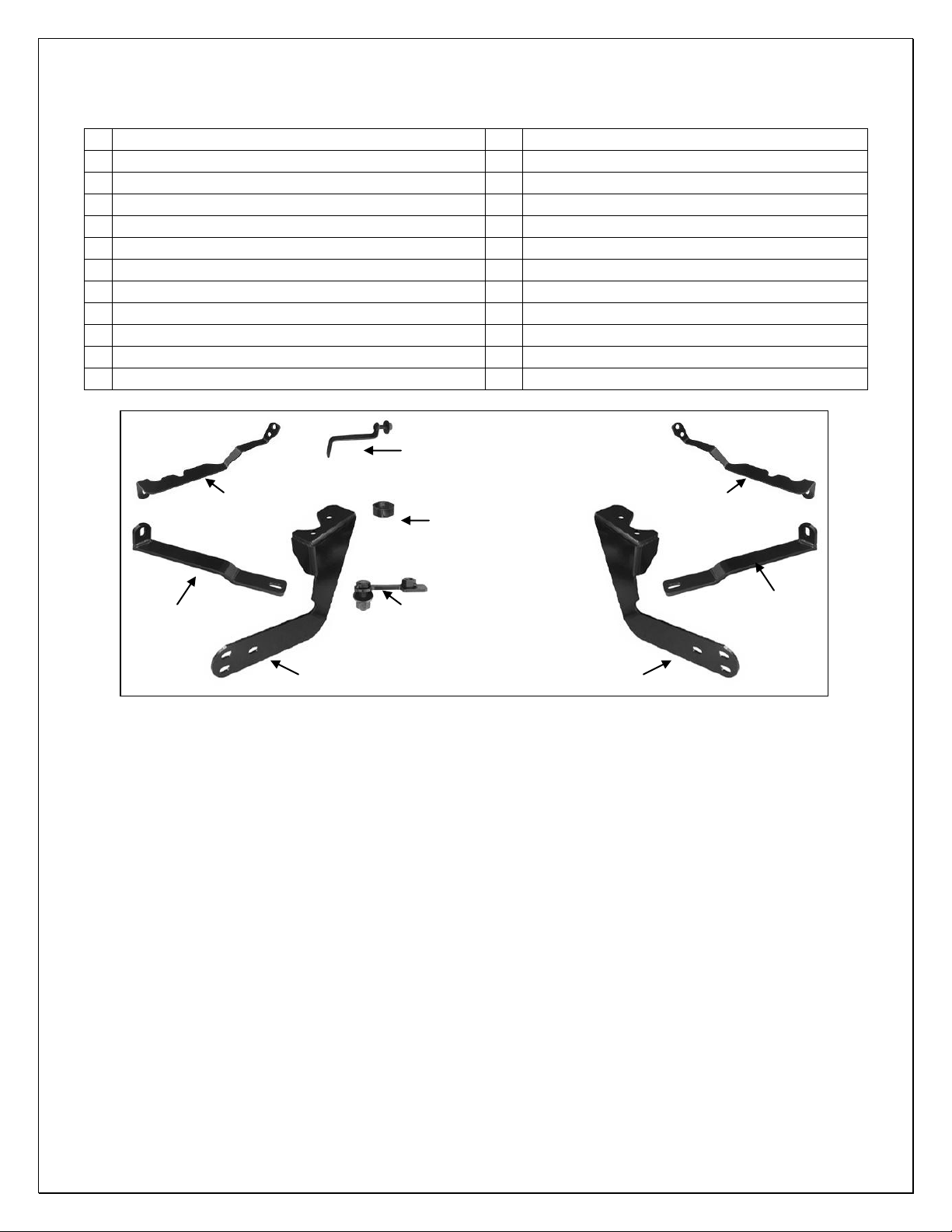
Passenger/Right
Side Frame Bracket
Driver/Left Side
Passenger/Right
Side Center
Bracket
Driver/Left Side
Center Bracket
Passenger/Right
Side Top Bracket
8mm x 25mm "Z" Bolt Plates
(2) Tube Spacers
(2) 12mm Bolt Plates w/ Nut
Driver/Left Side
Top Bracket
07-11 SPRINTER VAN
PARTS LIST:
PROCEDURE:
1. REMOVE CONTENTS FROM BOX. VERIFY ALL PARTS ARE PRESENT. READ
INSTRUCTIONS CAREFULLY BEFORE STARTING INSTALLATION. DRILLING MAY BE
REQUIRED (HIGHLY RECOMMENDED). ASSISTANCE IS RECOMMENDED.
2. Starting on the driver side of the vehicle, locate the factory hole in the bottom of the frame
channel, (Figure 1). Insert (1) 12mm Bolt and Nut Plate into the frame rail, (Figures 1 & 2).
NOTE: Insert Bolt Plate with welded nut toward the front of the vehicle. The offset Bolt and Nut
Plate is designed to clear hardware that may be attached to the inside of the frame, (Figure 1).
It is important to correctly orient the Bolt and Nut Plate in the frame channel.
3. Hang the driver side Frame Mounting Bracket from the Bolt and Nut Plate with (1) 12mm Flat
Washer, (1) 12mm Lock Washer and (1) 12mm Hex Nut, (Figures 3 & 4). Do not tighten
hardware at this time. Repeat this Step for passenger side Frame Bracket installation.
4. Next, remove the (2) Torx bolts in the bottom of the opening in the front bumper step area,
(Figure 5). Place a Tube Spacer into the driver side recess in the bumper cover, (Figure 6A &
6B). Position the driver side Center Bracket over the Tube Spacer. Use the included 8mm x
40mm Hex Bolt, 8mm x 24mm Large Flat Washer and 8mm Lock Washer to bolt the Bracket to
the front bumper, (Figure 7). Do not tighten hardware at this time. Repeat this Step for
passenger side Center Bracket installation.
5. Open the hood and locate the factory hole in the driver side of the radiator crossmember.
Remove the factory screw below the hole securing the top of the grille to the crossmember,
(Figure 8). Insert (1) 8mm "Z" Bolt Plate through the back of the crossmember and out of the
Page 1 of 6 6/6/11 Rev2 (DP)

GRILLE GUARD
07-11 SPRINTER VAN
hole, (Figures 9 & 10). NOTE: The back of the crossmember may be obstructed. Carefully
move the coolant tank or air intake if necessary to access the back of the crossmember. Use
(2-3) 8mm x 16mm Flat Washers on the "Z" Bolt Plate as a spacer between the crossmember
and the Top Bracket, (Figure 11). NOTE: It may be necessary to push down slightly on the top
of the plastic grille to provide clearance for the Spacer Washers. Secure the Top Bracket to the
8mm Bolt Plate using (1) 8mm x 16mm Flat Washer, (1) 8mm Lock Washer and (1) 8mm Hex
Nut, (Figure 11). Insert the factory screw through the hole in the Top Bracket, (Figure 12).
Leave hardware loose at this time. Repeat this Step for passenger side installation.
6. With assistance, position the Grille Guard face down on a clean surface in front of the vehicle,
(Figure 13). Hold the mounting tabs on the Grill Guard up to the outside of the Frame
Mounting Brackets. Line up the rear-most holes in the Mounting Brackets with the Grille Guard.
Insert (1) 12mm x 35mm Hex Bolt, (1) 12mm Lock Washer, (2) 12mm Flat Washers and (1)
12mm Hex Nut per side into the rear mounting holes to act as a hinge. Rotate the Grille Guard
up into position. Install the included 12mm Hex Bolts into the remaining (4) mounting holes,
(Figure 14). Do not tighten hardware at this time.
7. Attach the Grille Guard to the driver side Center Bracket using the included (1) 10mm x 25mm
Button Head Bolt, (2) 10mm Flat Washers and (1) 10mm Nylon Lock Nut, (Figure 15). Do not
tighten hardware at this time. Repeat this Step for passenger side Center Bracket installation.
8. Remove the top 6mm Button Head Bolt securing the headlight wire assembly to the Grille
Guard upright, (Figure 16). Bolt the Top Support Bracket to the inside of the upright using the
included longer 6mm x 25mm Button Head Bolt, 6mm STD Flat Washer, 6mm x 22mm Large
Flat Washer, (use inside against the Top Bracket), and 6mm Nylon Lock Nut, (Figure 17).
Repeat this Step for passenger side Top Bracket installation.
9. Align Grille Guard properly and tighten all hardware at this time.
10. Do periodic inspections to the installation to make sure that all hardware is secure and tight.
Additional drilling instructions (Highly Recommended)
11. Once you have the Grille Guard completely installed and properly aligned, use the second
hole, (unused till now), in the Frame Mounting Bracket as a template to mark the drilling
location on the bottom of the frame channel, (Figure 18). Do not mark the frame until after the
Grille Guard has been completely installed and properly aligned and adjusted. No adjustments
can be made after the frame is drilled.
12. Remove the Grille Guard, Frame Brackets and 12mm Bolt and Nut Plates from the vehicle.
NOTE: It is not necessary to remove the Center or Top Brackets from the vehicle.
13. Use a 1/2” drill bit to drill out the marked location, (Figure 19). IMPORTANT: Any cutting or
drilling tool may break or shatter. Government regulations require safety glasses & equipment
at all times when cutting or drilling.
14. Reinsert the Bolt and Nut Plates, (Step 2). Rotate the 12mm Bolt and Nut Plate to line up the
threaded nut with the previously drilled 1/2" hole. Use the included (2) 12mm x 35mm Hex
Bolts, (2) 12mm Lock Washers and (2) 12mm Flat Washers to secure the Frame Brackets to
the 12mm x 35mm Bolt and Nut Plate, (Figure 20). Re-install the Grille Guard as previously
described in Steps 2 - 8. NOTE: Align Grille Guard properly and tighten all hardware.
15. Do periodic inspections to the installation to make sure that all hardware is secure and tight.
To protect your investment, wax this product after installing. Regular waxing is recommended to add a
protective layer over the finish. Do not use any type of polish or wax that may contain abrasives that could
damage the finish.
For stainless steel: Aluminum polish may be used to polish small scratches and scuffs on the finish. Mild
soap may be used also to clean the Grille Guard.
For gloss black finishes: Mild soap may be used to clean the Grille Guard.
Page 2 of 6 6/6/11 Rev2 (DP)

GRILLE GUARD
Fig 1
Front
Fig 2
Fig 3
Fig 4
Fig 6A
Fig 5
Front
Front
Remove (2) factory screws (Torx head)
12mm Flat Washer
12mm Lock Washer
12mm Hex Nut
Front
Fig 6B
07-11 SPRINTER VAN
Driver Side Installation Pictured
Page 3 of 6 6/6/11 Rev2 (DP)

Driver Side Installation Pictured
Remove factory screw
Insert 8mm x 25mm "Z"
Bolt Plate into the factory
hole from behind the
radiator crossmember
Insert (2-3) 8mm x16mm Flat Washers as a spacer
between the Top Bracket and the radiator
crossmember. NOTE: It may be necessary to gently
push down on the plastic grille to provide clearance
for the Flat Washers/Spacer behind the Top Bracket.
Secure the Top Bracket to the Bolt Plate with:
8mm Lock Washer
8mm x 16mm x 1.6mm Flat Washer
8mm Hex Nut
Fig 8
(Fig 7) Pictured with Grille Guard Installed
Fig 10
(Fig 9) Back of radiator crossmember pictured
Fig 11
8mm x 40mm Hex Bolt
8mm Lock Washer
8mm x 24mm x 2mm Flat Washer
Top of plastic grille
Front
Front
Front
Front
Front
Factory hole
in radiator
crossmember
GRILLE GUARD
07-11 SPRINTER VAN
Page 4 of 6 6/6/11 Rev2 (DP)

Tilt the Grille Guard up into
position then install the
remaining (4) mounting bolts.
Replace top button head bolt with:
6mm x 25mm Button Head Bolt
6mm x 22mm x 2mm Large Flat
Washer (against Top Bracket)
Reuse the following hardware:
6mm STD Flat Washer
6mm Nylon Lock Nut
Front
Fig 14
Fig 13
Front
Fig 12
Reinstall the factory
button head screw
Fig 16
Fig 15
(1) 12mm x 35mm Hex Bolt
(2) 12mm Flat Washers
(1) 12mm Lock Washer
(1) 12mm Hex Nut
10mm x 25mm Button
Head Bolt
(2) 10mm Flat Washers
10mm Nylon Lock Nut
Front
Front
GRILLE GUARD
07-11 SPRINTER VAN
Driver Side Installation Pictured
Page 5 of 6 6/6/11 Rev2 (DP)

GRILLE GUARD
Front
Fig 20
Complete Installation
Front
Front
Fig 17
Mark hole location
onto bottom of
frame channel.
Remove Grille Guard
and Frame Brackets
Fig 18
(Fig 19) Drill 1/2" hole in bottom of frame channel
Additional Drilling Instructions
Highly Recommended
6mm x 22mm x 2mm
Large Flat Washer
(against Top Bracket)
6mm Nylon Lock Nut
12mm x 35mm Hex Bolt
12mm Flat Washer
12mm Lock Washer
Front
Additional Drilling Instructions
Highly Recommended
07-11 SPRINTER VAN
Driver Side Installation Pictured
Page 6 of 6 6/6/11 Rev2 (DP)
 Loading...