

Steelcraft Automotive 51340 User Manual
INSTALLATION INSTRUCTIONS
PART NUMBER
GRILLE GUARD
07 FORD EDGE
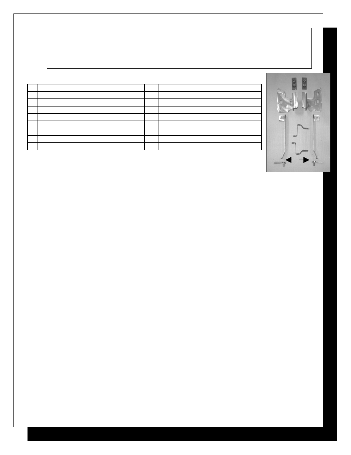
PARTS LIST:
1 Sport Bar 4 6mm ID x 18mm OD x 1.5mm Flat Washers
1 Driver/Left Mounting Bracket (A) 2 6-1.00 x 20mm Button Head Bolts
1 Passenger/Right Mounting Bracket (B) 2 10-1.50mm x 30mm Hex Head Bolts
1 Driver/Left Support Bracket (C) 4 10mm Nylock Nuts
1 Passenger/Right Support Bracket (D) 6 10mm ID x 26mm OD x 3mm Flat Washers
2 12mm Double Nut Plates (E) 8 12-1.75mm x 35mm Hex Head Bolts
2 Top Brackets (F) 4 12mm Lock Washers
2 10mm Bolt Plates (G) 4 12mm Nylock Nuts
2 6mm Nylock Nuts 12 12mm ID x 29mm OD x 3mm Flat Washers
(A)
(C) (D)
(F)
(E)
(B)
PROCEDURE:
(G)
1. REMOVE CONTENTS FROM BOX. VERIFY ALL PARTS ARE PRESENT. READ INSTRUCTIONS CAREFULLY
BEFORE STARTING INSTALLATION. DO NOT ATTEMPT INSTALLATION ALONE; PERSONAL INJURY OR
DAMAGE TO THE TRUCK MAY RESULT.
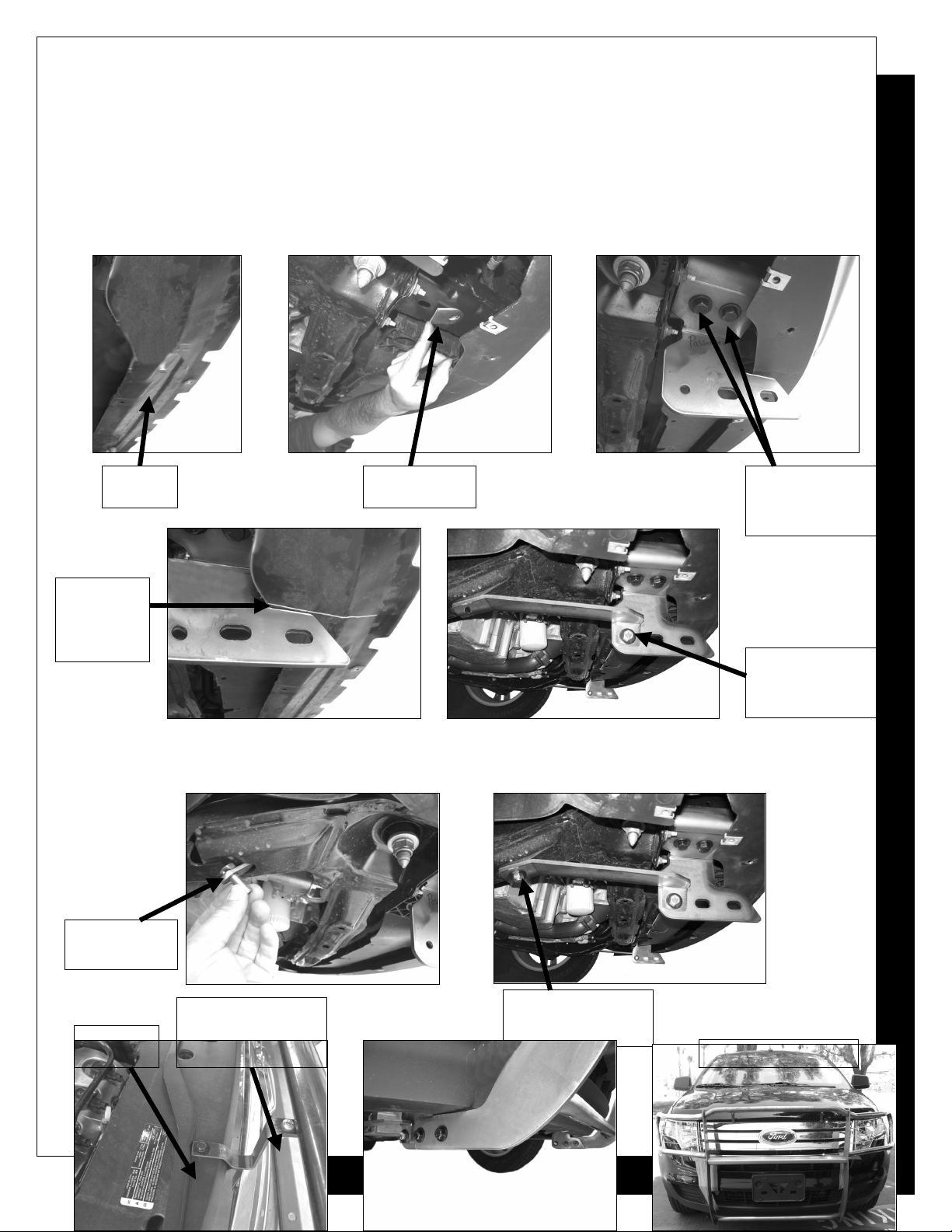
2. NOTE: The factory lower air dam and the bottom plastic shroud (Figure 1) must be removed to install this Grille Guard.
From underside of vehicle, use an 8mm socket/wrench to remove 7 screws and a flat screw driver to remove the 3 clips
from across the bottom plastic shroud. Once you have removed the plastic shroud, use a 10mm wrench to remove the
10 bolts and 8mm socket to remove 2 crews across the lower air dam. NOTE: You will not be reinstalling the front air
dam.
3. Insert (1) 12mm Double Nut Plate into front of passenger side frame and align the holes on the Double Nut Plate with
the factory holes on the frame (Figure 2).
4. Determine passenger and driver side Mounting Brackets. Hang passenger side Mounting Bracket into position by
partially threading (2) 12-1.75mm x 35mm Hex Head Bolts, (2) 12mm Lock Washers, and (2) 12mm Flat Washers
through factory holes and into previously inserted Double Nut Plate (Figure 3).
5. Repeat steps three and four for driver side Mounting Bracket.
6. NOTE: To re-install the factory plastic shroud cutting is required. Insert factory plastic shroud from front of vehicle and
slide it between Mounting Brackets and vehicle. Center plastic shroud and make sure the holes on the plastic shroud will
line up with their original mounting holes on the vehicle after cutting, and then mark the cutting location (Figure 4).
7. Remove plastic shroud and place it on a working area. Using a hacksaw, cut about 5” starting from the back and
towards the front of plastic shroud.
8. Re-install plastic shroud using the factory hardware removed in step two.
9. Locate passenger side Support Bracket and attach it to rear hole on the previously attached Mounting Bracket using the
included (1) 10-1.50mm x 30mm Hex Head Bolt, (1) 10mm Nylock Nut, and (2) 10mm Flat Washers (Figure 5). Do not
tighten at this time.
10. Extend Support Bracket towards the rear of the vehicle. The opposite mounting hole on the Support Bracket should
reach its mounting location on the frame. Insert (1) Bolt Plate into factory hole on the frame (Figure 6).
11. Attach the rear mounting location on the Support Bracket to previously inserted Bolt Plate. Secure Support Bracket
using (1) 10mm Flat Washer and (1) 10mm Nylock Nut (Figure 7). Do not tighten at this time.
12. Repeat steps 9-11 for driver side Support Bracket.
13. Open the hood and remove the two outer factory bolts located on the upper black section of chrome grille shell. Attach
Top Brackets to these factory holes using the factory bolts removed in this step (Figure 8).
14. With help position Sport Bar on the outer side on Mounting Brackets. Attach Sport Bar to Mounting Brackets using (4)
12mm x 35mm Hex Head Bolts, (4) 12mm Nylock Nuts, and (8) 12mm Flat Washers (Figure 8). Do not tighten at this
time.
15. Attach Grille Guard to Top Brackets using the included (2) 6mm x 20mm Button Head Bolts, (2) 6mm Nylock Nuts, (4)
6mm Flat Washers.
16. Level and adjust Sport Bar, and then tighten all hardware at this time.
(AM)
Page 1 of 3 4/30/07
17. Do periodic inspections to the installation to make sure that all hardware is secure and tight.
(Passenger Side Mounting Bracket and Passenger Side Support Bracket installation
Shown)
Fig 1 Fig 2 Fig 3
Cut where
line is,
(about 5
inches)
Plastic
Shroud
12mmDouble
Nut Plate
12mm x 35mm Hex
Head Bolts
12mm Lock Washers
12mm Flat Washers
10mm x 30mm Hex
Head Bolts
Fig 5Fig 4
10mm Nylock Nut
10mm Flat Washers
(AM)
10mm Bolt
Plate
Factory
Bolt
Fig 6 Fig 7
6mm x 20mm Button
Head Bolt
6mm Nylock Nut
6mm Flat Washers
(Bolt Plate)
10mm Flat Washer
10mm Nylock Nut
Installation Complete
Page 2 of 3 4/30/07
 Loading...