

Steelcraft Automotive 213900 User Manual
PARTS LIST:
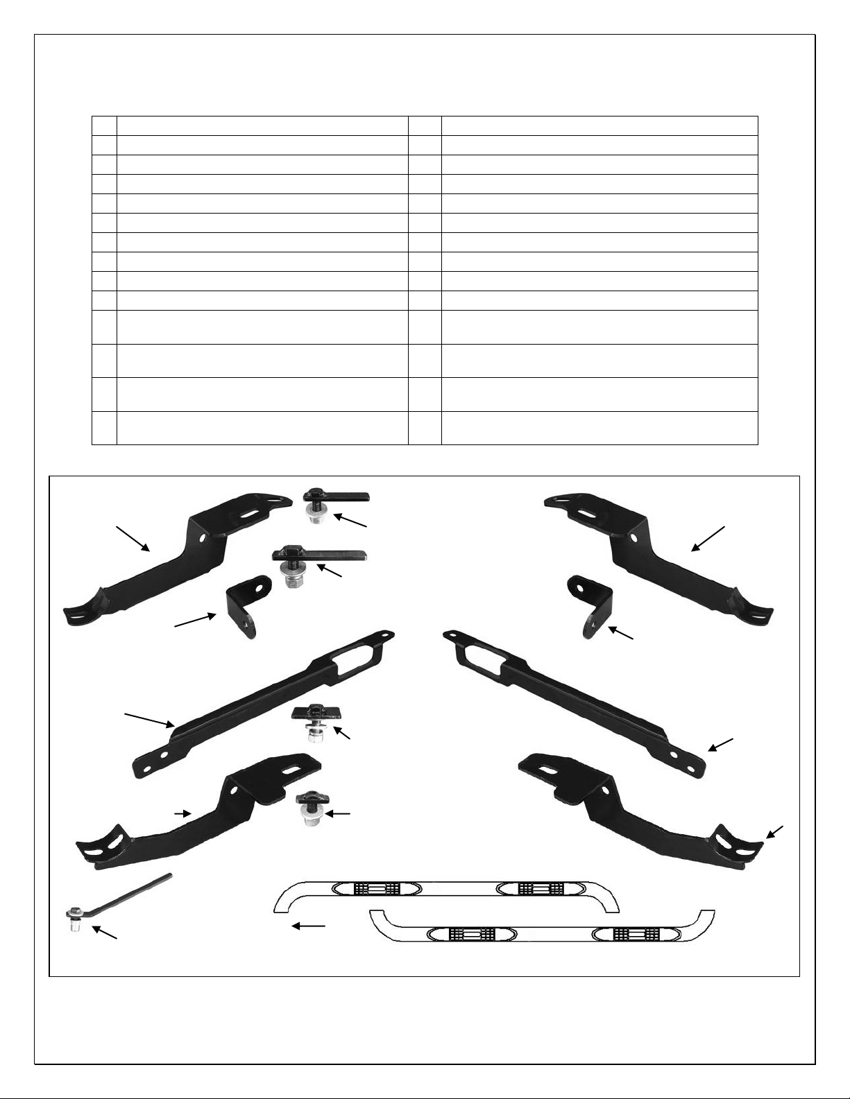
1
Driver/Left Sidebar
2
8mm Threaded Inserts
1
Passenger/Right Sidebar
1
Insert Tool
1
Driver/Left Front Mounting Bracket
4
12-1.75mm x 32mm OD x 3mm Flat Washers
1
Passenger/Right Front Mounting Bracket
4
12mm Lock Washers
1
Driver/Left Rear Mounting Bracket
4
12mm Hex Nuts
1
Passenger/Right Rear Mounting Bracket
6
10-1.50mm x 30mm Hex Bolts
1
Driver/Left Front Support Bracket
4
10mm x 27mm OD x 3mm Large Flat Washers
1
Passenger/Right Front Support Bracket
12
10mm x 20mm OD x 2mm Small Flat Washers
1
Driver/Left Rear Support Bracket
4
10mm Lock Washers
1
Passenger/Right Rear Support Bracket
6
10mm Nylon Lock Nuts
2
12-1.75mm x 35mm T-Bolt Plate (Front
Bracket Only)
4
10mm Hex Nuts
2
10-1.50mm x 35mm "Wide" T-Bolt Plate (Front
Support Bracket Only)
10
8-1.25mm x 30mm Hex Bolts
2
12-1.75mm x 40mm Long Bolt Plate (Rear
Bracket Only)
10
8mm x 24mm OD x 2mm Flat washers
2
10-1.50mm x 35mm Bolt Plate (Rear Bracket
Only)
10
8mm Lock Washers
Driver/Left Rear
Mounting Bracket
Driver/Left Rear
Support Bracket
Driver/Left Front
Mounting Bracket
Driver/Left Front
Support Bracket
Passenger/Right
Rear Mounting
Bracket
Passenger/Right Rear
Support Bracket
Passenger/Right
Front Support Bracket
Passenger/Right Front
Mounting Bracket
(2) 10mm x 35mm Bolt
Plate (Rear Bracket Only)
(2) 12mm x 40mm Long Bolt
Plate (Rear Bracket Only)
(2) 10mm x 35mm "Wide T" Bolt
Plate (Front Support Bracket Only)
(2) 12mm x 35mm "T" Bolt
Plate (Front Bracket Only)
8mm Threaded Insert
Tool (pictured w/insert
and hardware)
Passenger/Right Sidebar
Driver/Left Sidebar
Front
SIDEBARS
2011 FORD EXPLORER
Page 1 of 5 4/27/11 (DP)

SIDEBARS
2011 FORD EXPLORER
PROCEDURE:
1. REMOVE CONTENTS FROM BOX. VERIFY ALL PARTS ARE PRESENT. READ INSTRUCTIONS
CAREFULLY BEFORE STARTING INSTALLATION. DRILLING IS REQUIRED. ASSISTANCE IS
RECOMMENDED.
2. Start installation under the driver side of the vehicle. Select (1) 12mm x 35mm Small T-Bolt Plate and
insert it into the factory oval hole in the floor panel, (Figures 1A & 1B). Rotate the Bolt Plate 90degrees so that the plate is across the oval hole. Select the driver side front Mounting Bracket. Hang
the Bracket from the Bolt Plate with (1) 12mm Flat Washer, (1) 12mm Lock Washer and (1) 12mm Hex
Nut, (Figure 2). NOTE: Make sure that the mounting flange on the Front Bracket is lined up properly
with the indent in the floor panel. The Front Mounting Bracket must sit flat against the floor panel. Do
not tighten hardware at this time.
3. Insert (1) 10mm x 35mm Wide T-Bolt Plate, (Figure 3B), into the large round hole in the bottom of the
inner frame channel, (Figure 3A). Rotate the Bolt Plate so that the plate is inline with the Support
Bracket and 90-degrees to the direction of the frame channel. Select the driver side Front Support
Bracket. Hang the Support Bracket from the Bolt Plate and secure it with the included (1) 10mm x
27mm Large Flat Washer, (1) 10mm Lock Washer and (1) 10mm Hex Nut, (Figure 4). Do not tighten
hardware at this time.
4. Hold the Support Bracket up to the back of the Front Bracket and line up the (2) mounting holes. Bolt
the two Brackets together with the included (2) 10mm x 30mm Hex Bolts, (4) 10mm x 20mm Small Flat
Washers and (2) 10mm Nylon Lock Nuts, (Figure 5). Snug but do not tighten hardware at this time.
5. Select the driver side rear Mounting Bracket and (1) "L" Rear Support Bracket. Bolt the Support Bracket
to the front facing side of the Mounting Bracket with (1) 10mm x 30mm Hex Bolt, (2) 10mm x 20mm
Small Flat Washers and (1) 10mm Nylon Lock Nut, (Figures 7A & 7B).
6. Locate the oval and round holes in the floor panel toward the rear of the vehicle, (Figure 6A). Insert (1)
10mm x 35mm Bolt Plate into the round hole, (Figure 6B). Insert (1) 12mm x 40mm Long Bolt Plate
into the oval hole next to the pinch weld, (Figure 6C). Rotate the Bolt Plate 90-degrees so that the plate
is across the oval hole. Position the Rear Mounting Bracket over the (2) Bolt Plates. Secure the Bracket
to the 12mm Bolt Plate with (1) 12mm Flat Washer, (1) 12mm Lock Washer and (1) 12mm Hex Nut,
(Figure 7). Bolt the Bracket to the 10mm Bolt Plate with the included (1) 10mm x 27mm OD Large Flat
Washer, (1) 10mm Lock Washer and (1) 10mm Hex Nut. Hold the Support Bracket firmly against the
back of the pinch weld and tighten the hardware at this time.
7. Select the driver Sidebar and carefully place it onto the Mounting Brackets to avoid damaging the finish
on the Sidebar. Line up the holes in the Sidebar with the Mounting Brackets and bolt together with the
included (4) 8mm x 30mm Hex Bolts, (4) 8mm Flat Washers and (4) 8mm Lock Washers, (Figure 8).
8. Level and adjust the Sidebar and tighten all hardware except the 10mm hex bolt securing the "L" Rear
Support Bracket to the Rear Mounting Bracket, (Figure 9).
9. Move back to the driver side Rear Mounting Bracket. Hold the "L" Support Bracket firmly against the
back of the pinch weld. Mark the mounting hole location on the "L" Support Bracket onto the pinch
weld, (Figure 9). Check the Sidebar for level before proceeding. CAUTION: Do not drill the hole too
close to the bottom edge of the pinch weld.
10. Remove the "L" Support Bracket. Carefully drill this location with a 7/16" drill bit, (Figure 10A).
IMPORTANT! Be very careful and drill slowly through the pinch weld to avoid damaging the outer
rocker panel cover. Any cutting or drilling tool may break or shatter. Government regulations require
safety glasses & equipment at all times when cutting or drilling.
11. Assemble the Threaded Insert installation tool as pictured in Figure 10B. Hold the handle and push the
insert into the drilled hole in the pinch weld. NOTE: Insert must fit snug in hole. If necessary, use a
small hammer to carefully tap the insert into the hole until the rim on the insert is flush against the pinch
weld. Firmly hold the tool handle and tighten the hex bolt in the tool to expand the insert in the hole.
Continue until threads are flush with the top of the insert, (Figure 10C). Remove the tool and hardware.
Bolt the Support Bracket to the threaded insert with (1) 8mm x 30mm Hex Bolt, (1) 8mm Flat Washer
and (1) 8mm Lock Washer, (Figure 11). Tighten hardware at this time.
12. Repeat Steps 2-11 for passenger/right Sidebar installation.
13. Do periodic inspections to the installation to make sure that all hardware is secure and tight.
Page 2 of 5 4/27/11 (DP)
 Loading...