

Steelcraft Automotive 180310 User Manual
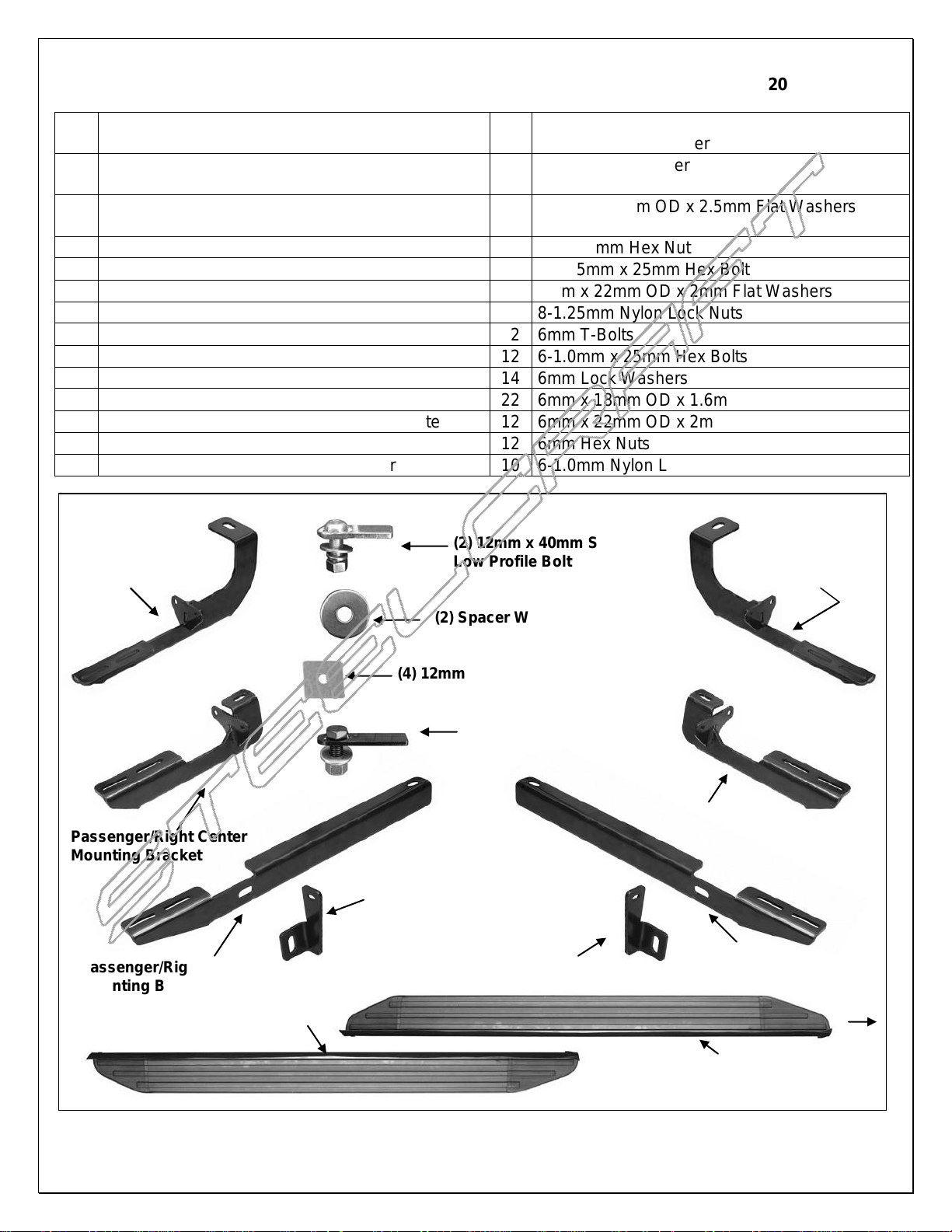
PARTS LIST:
1
Driver/Left Running Board with 1” Rubber Backing
(use on SX & Limited models)
4
12mm Plastic Retainer
1
Passenger/Right Running Board with 1” Rubber
Backing (use on SX & Limited models)
4
12mm Lock Washer
2
2” Tall Rubber Backing (use on LX and EX
models)
4
12mm x 24mm OD x 2.5mm Flat Washers
1
Driver/Left Front Mounting Bracket
4
12-1.75mm Hex Nut
1
Passenger/Right Front Mounting Bracket
2
8-1.25mm x 25mm Hex Bolt
1
Driver/Left Front Support Bracket
4
8mm x 22mm OD x 2mm Flat Washers
1
Passenger/Right Front Support Bracket
2
8-1.25mm Nylon Lock Nuts
1
Driver/Left Center Mounting Bracket
12
6mm T-Bolts
1
Passenger/Right Center Mounting Bracket
12
6-1.0mm x 25mm Hex Bolts
1
Driver/Left Rear Mounting Bracket
14
6mm Lock Washers
1
Passenger/Right Rear Mounting Bracket
22
6mm x 18mm OD x 1.6mm Small Flat Washers
2
12mm x 40mm Short Button Head Bolt Plate
12
6mm x 22mm OD x 2mm STD Flat Washers
2
12mm x 35mm Long Bolt Plate
12
6mm Hex Nuts
2
14mm x 50mm x 4mm Spacer Washer
10
6-1.0mm Nylon Lock Nuts
Driver/Left Front
Mounting Bracket
Passenger/Right
Rear Mounting
Bracket
Driver/Left
Rear Mounting
Bracket
(2) 12mm x 40mm Short
Low Profile Bolt Plates
(2) 12mm x 35mm Long
Bolt Plates
Driver/Left Running Board
Passenger/Right Running Board
Front
(2) Spacer Washers
Passenger/Right Front
Mounting Bracket
Passenger/Right Front
Support Bracket
Driver/Left Center
Mounting Bracket
Driver/Left Front
Support Bracket
Passenger/Right Center
Mounting Bracket
(4) 12mm Plastic Retainers
ALUMINUM VIEWPOINT RUNNING BOARDS
2014 SORENTO
Page 1 of 8 12/4/13 Rev1 (DP)

ALUMINUM VIEWPOINT RUNNING BOARDS
2014 SORENTO
PROCEDURE:
REMOVE CONTENTS FROM BOX. VERIFY ALL PARTS ARE PRESENT. READ INSTRUCTIONS
CAREFULLY BEFORE STARTING INSTALLATION. CUTTING AND DRILLING IS REQUIRED.
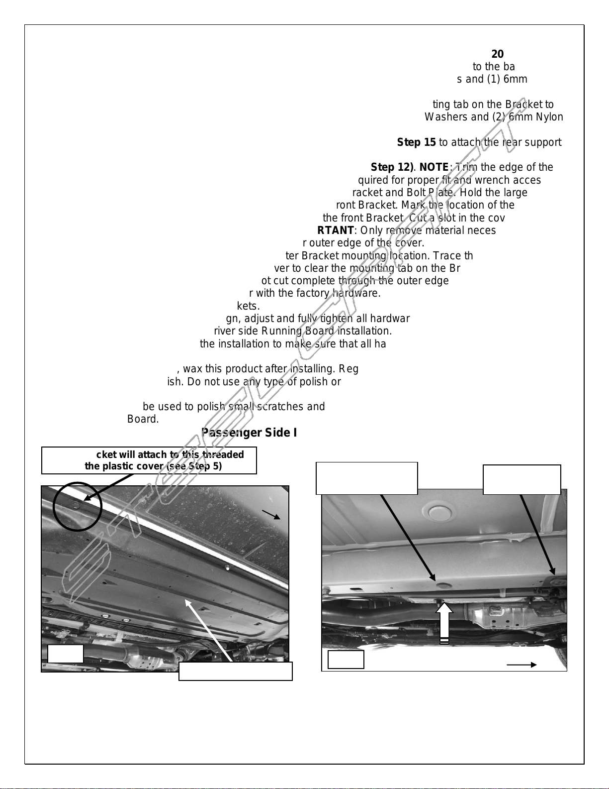
1. Starting at the front, passenger side of the vehicle, locate and remove the plastic cover attached to the
bottom of the floor panel, (Figure 1). Next, locate and remove the rubber plug in the bottom of the inner
frame channel, (Figure 2). Partially thread (1) 12mm Plastic Retainer onto (1) 12mm x 35mm Long Bolt
Plate. Insert the Bolt Plate into the hole and thread the Retainer down tight to help hold the Bolt Plate in
position, (Figures 3A & 3B).
2. Select (1) Passenger Front Bracket and (1) Passenger Front Support Bracket, (Figure 4). Bolt the bent
end of the Support Bracket to the front facing side of the front Bracket with (1) 8mm x 25mm Hex Bolt,
(2) 8mm Flat Washers, (1) 8mm Lock Washer and (1) 8mm Hex Nut. Snug but do not tighten hardware
at this time.
3. Next, attach the inner end of the front Bracket assembly to the Bolt Plate with (1) 12mm Flat Washer (1)
12mm Lock Washer and (1) 12mm Hex Nut, (Figure 5). Leave hardware loose at this time.
4. Line up the mounting tab on the front Support Bracket with the back of the pinch weld. Use a clamp to
temporarily attach the Support Bracket to the pinch weld, (Figure 6).
5. Move toward the center of the vehicle. Locate the last/rear threaded hole in the outer frame channel for
the plastic cover removed in Step 1, (Figure 1). Select the passenger Center Bracket. Bolt the Bracket
to the threaded hole with (1) 6mm x 25mm Hex Bolt, (1) 6mm Lock Washer and (1) 6mm x 22mm STD
Flat Washer, (Figure 7). Do not tighten the hardware at this time.
6. Continue along the side of the vehicle and locate the rubber plug in the bottom of the floor panel directly
in front of the rear suspension mount, (Figure 8). Remove the plug. Partially thread (1) 12mm Plastic
Retainer onto (1) 12mm x 40mm Short Low Profile Bolt Plate. Repeat Step 1 to insert the Bolt Plate
with Retainer into the hole, (Figures 9A & 9B). Select the passenger rear Bracket. Slide (1) Large
Spacer Washer over the Bolt Plate and Retainer, (Figure 10A & 10B), then attach the passenger Rear
Bracket to the Bolt Plate with (1) 12mm Flat Washer, (1) 12mm Lock Washer and (1) 12mm Hex Nut,
(Figure 11).
7. Push the mounting tab on the rear Bracket up tight against the back of the pinch weld. Use a clamp to
help hold the Bracket in place if necessary. Snug but do not tighten the hardware at this time.
8. Carefully unwrap the Running Boards. Determine the correct rubber backing for your model.
SX and Limited models:
Install the Running Boards as packaged with the shorter 1" Rubber Backing Strip and continue
on to Step 9.
LX and EX models:
The Running Boards are shipped with 1" tall Rubber Backing Strips. Slide the Rubber Strip out
of the end of the passenger side Running Board and replace it with the included taller 2" Rubber
Strip, (Figure 12). Repeat this Step for the driver side Running Board.
9. Select the passenger side Running Board. From the front, slide (3) 6mm T-Bolts into each of the two
channels in the bottom of the Running Board, (Figure 13). Slide the T-Bolts forward or back to line up
with the slots in the (3) Mounting Brackets. Hold the Running Board up to the vehicle at a slight angle
and gently push it into position against the rocker panel. Insert the T-Bolts through the slots in the
Brackets. NOTE: Depending on model, it may be necessary to loosen the (3) Brackets in order to fit the
Running Board between the rocker panel and the Brackets. Reattach Brackets if necessary.
10. Attach the Running Board to the (3) Mounting Brackets with the included (6) 6mm x 22mm STD Flat
Washers, (6) 6mm Lock Washers and (6) 6mm Hex Nuts, (Figure 14). Do not tighten hardware.
11. Level and adjust the Running Board properly and tighten all Bracket to vehicle hardware. Make sure
that the Running Board is level and that the mounting holes in the Brackets are not too close to the
bottom edge of the pinch weld before marking any of the holes for the Brackets, (Figure 15).
12. Mark the front, center and rear Support Bracket slot locations onto the back of the pinch weld, (Figure
16). Temporarily remove the Running Board and Brackets. Remove the screws attaching the plastic
rocker cover to the bottom of the body, (Figure 11).
13. Drill 1/4" holes, (5 total), through the pinch weld at the previously marked front, center and rear Bracket
locations. IMPORTANT: Be careful to avoid damaging the outer plastic rocker cover.
Page 2 of 8 12/4/13 Rev1 (DP)
ALUMINUM VIEWPOINT RUNNING BOARDS
Fig 1
Fig 2
Do not remove
this plug
Front
Remove plastic cover
Front
Remove this rubber
plug only
Center Bracket will attach to this threaded
hole for the plastic cover (see Step 5)
2014 SORENTO
14. Remove the front Support Bracket from the front Bracket. Bolt the Support Bracket to the back of the
pinch weld with (1) 6mm x 25mm Hex Bolt, (2) 6mm x 18mm Small Flat Washers and (1) 6mm Nylon
Lock Nut, (Figure 17). Leave hardware loose at this time.
15. Move to the center location and reinstall the Center Bracket. Bolt the mounting tab on the Bracket to the
pinch weld with (2) 6mm x 25mm Hex Bolts, (4) 6mm x 18mm Small Flat Washers and (2) 6mm Nylon
Lock Nuts, (Figure 17). Leave hardware loose at this time.
16. Move to the rear Bracket location. Reinstall the Bracket and repeat Step 15 to attach the rear support
tab on the Bracket, (Figure 17).
17. Reattach the lower rocker cover with the factory screws, (see Step 12). NOTE: Trim the edge of the
rocker cover around the 6mm Hex Bolts in pinch weld as required for proper fit and wrench access.
18. Temporarily attach the front Bracket to the front Support Bracket and Bolt Plate. Hold the large plastic
cover removed in Step 1 up against the bottom of the front Bracket. Mark the location of the Bracket
onto the inside of the cover, (Figure 18A). Remove the front Bracket. Cut a slot in the cover with a
sharp knife or hacksaw blade, (Figure 18B). IMPORTANT: Only remove material necessary to clear
the front Bracket. Do not cut through the inner or outer edge of the cover.
19. Next, locate the hole in the cover for the center Bracket mounting location. Trace the Bracket outline
onto the cover. Cut a section out of the cover to clear the mounting tab on the Bracket, (Figure 18B).
IMPORTANT: Be very careful and do not cut complete through the outer edge. Remove the center
Bracket and reinstall the plastic cover with the factory hardware.
20. Reinstall the front and center Brackets.
21. Reinstall the Running Board. Align, adjust and fully tighten all hardware at this time.
22. Repeat Steps 1 - 21 for the driver side Running Board installation.
23. Do periodic inspections of the installation to make sure that all hardware is secure and tight.
To protect your investment, wax this product after installing. Regular waxing is recommended to add a
protective layer over the finish. Do not use any type of polish or wax that may contain abrasives that could
damage the finish.
Aluminum polish may be used to polish small scratches and scuffs on the finish. Mild soap may be used also to
clean the Running Board.
Passenger Side Installation Pictured
Page 3 of 8 12/4/13 Rev1 (DP)
 Loading...