

Steelcraft Automotive 170700 User Manual
ALUMINUM VIEWPOINT RUNNING BOARDS
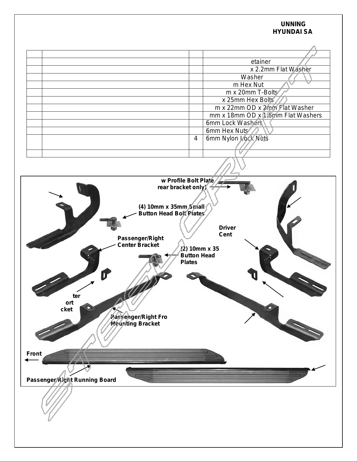
(1) 10mm x 35mm Low Profile Bolt Plate
(use for driver side rear bracket only)
(4) 10mm x 35mm Small
Button Head Bolt Plates
(2) 10mm x 35mm
Button Head Bolt
Plates
Description
Description
1
Driver/Left Side Running Board
7
10mm Plastic Retainer
1
Passenger/Right Side Running Board
7
10mm x 24mm x 2.2mm Flat Washer
1
Driver/Left Front Bracket
7
10mm Lock Washer
1
Passenger/Right Front Bracket
7
10-1.50mm Hex Nut
1
Driver/Left Center Bracket
12
6-1.0mm x 20mm T-Bolts
1
Passenger/Right Center Bracket
5
6mm x 25mm Hex Bolts
1
Driver Rear Bracket
17
6mm x 22mm OD x 2mm Flat Washer
1
Passenger Rear Bracket
4
6mm x 18mm OD x 1.6mm Flat Washers
2
Center "L" Cover Support Brackets
13
6mm Lock Washers
2
10-1.50mm x 35mm Button Head Bolt Plates
12
6mm Hex Nuts
4
10-1.50mm x 35mm Small Button Head Bolt
Plates
4
6mm Nylon Lock Nuts
1
10-1.50 x 35mm Special Low Profile Bolt Plate
Passenger/Right
Rear Mounting
Bracket
Passenger/Right
Center Bracket
"L" Center
Support
Bracket
Passenger/Right Front
Mounting Bracket
Driver/Left Front
Mounting Bracket
Driver/Left
Center Bracket
Driver/Left
Rear
Mounting
Bracket
Passenger/Right Running Board
Driver/Left Running Board
Front
"L" Center
Support
Bracket
PARTS LIST:
2013 HYUNDAI SANTA FE
Page 1 of 8 4/15/13(DP)
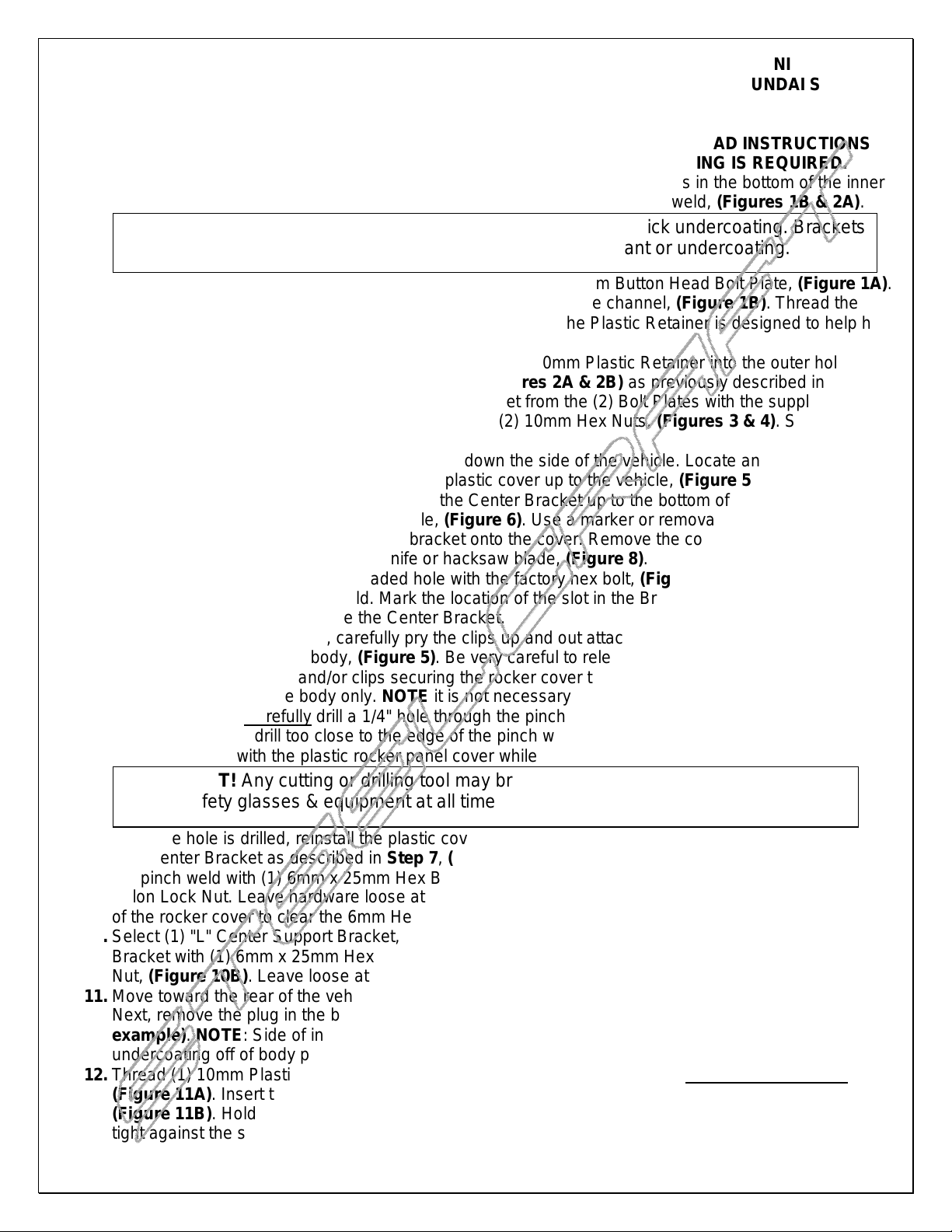
ALUMINUM VIEWPOINT RUNNING BOARDS
IMPORTANT! Any cutting or drilling tool may break or shatter. Government regulations
require safety glasses & equipment at all times when cutting or drilling.
NOTE: All mounting locations may be covered with sealant or thick undercoating. Brackets
must fit flush against sheet metal. Scrape off any excess sealant or undercoating.
2013 HYUNDAI SANTA FE
PROCEDURE:
1. REMOVE CONTENTS FROM BOX. VERIFY ALL PARTS ARE PRESENT. READ INSTRUCTIONS
CAREFULLY BEFORE STARTING INSTALLATION. CUTTING AND DRILLING IS REQUIRED.
2. Starting on the driver side of the vehicle, locate and remove the rubber plugs in the bottom of the inner
frame channel and in the bottom of the outer body panel next to the pinch weld, (Figures 1B & 2A).
3. Partially thread (1) 10mm Plastic Retainer onto (1) 10mm x 35mm Button Head Bolt Plate, (Figure 1A).
Insert the Bolt Plate into the inner hole in the bottom of the frame channel, (Figure 1B). Thread the
Retainer all the way down against the sheet metal. NOTE: The Plastic Retainer is designed to help hold
the Bolt Plate in place during Bracket installation.
4. Next, insert (1) 10mm x 35mm Small Bolt Plate with (1) 10mm Plastic Retainer into the outer hole in the
bottom of the body panel next to the pinch weld, (Figures 2A & 2B) as previously described in Step 3.
Select the driver side Front Bracket. Hang the Bracket from the (2) Bolt Plates with the supplied (2)
10mm Flat Washers, (2) 10mm Lock Washers and (2) 10mm Hex Nuts, (Figures 3 & 4). Snug but do
not fully tighten hardware at this time.
5. Move to the center mounting location mid way down the side of the vehicle. Locate and remove the last
factory 6mm hex bolt holding the end of the plastic cover up to the vehicle, (Figure 5).
6. Select the driver side Center Bracket. Hold the Center Bracket up to the bottom of the body panel over
the plastic cover and factory threaded hole, (Figure 6). Use a marker or removable tape, (masking tape
for example), to trace the outline of the bracket onto the cover. Remove the cover. Cut out the marked
section from the cover with a sharp knife or hacksaw blade, (Figure 8).
7. Bolt the Center Bracket to the threaded hole with the factory hex bolt, (Figure 7). Push the Bracket up
against the back of the pinch weld. Mark the location of the slot in the Bracket onto the back of the
pinch weld, (Figure 7). Remove the Center Bracket.
8. With a flat blade screwdriver, carefully pry the clips up and out attaching the bottom of the rocker panel
cover to the bottom of the body, (Figure 5). Be very careful to release all of the bottom and inner clips.
Also remove the screws and/or clips securing the rocker cover to the front and rear tire openings. Pull
the cover away from the body only. NOTE it is not necessary but may be easier to completely remove
the rocker cover. Carefully drill a 1/4" hole through the pinch weld in the location marked in Step 7,
(Figure 7). Do not drill too close to the edge of the pinch weld. Do not allow drill motor or drill bit to
come in contact with the plastic rocker panel cover while drilling.
9. Once the hole is drilled, reinstall the plastic cover removed in Step 6, (Figure 8). Reinstall the driver
side Center Bracket as described in Step 7, (Figures 9A & 9B). Bolt the Bracket to the drilled hole in
the pinch weld with (1) 6mm x 25mm Hex Bolt, (2) 6mm x 18mm Small Flat Washers and (1) 6mm
Nylon Lock Nut. Leave hardware loose at this time. NOTE: It may be necessary to cut a small piece out
of the rocker cover to clear the 6mm Hex Bolt in the pinch weld. Leave rocker cover loose at this time.
10. Select (1) "L" Center Support Bracket, (Figure 10A). Bolt the L-Bracket to the front of the Center
Bracket with (1) 6mm x 25mm Hex Bolt, (2) 6mm x 22mm Large Flat Washers and (1) 6mm Nylon Lock
Nut, (Figure 10B). Leave loose at this time.
11. Move toward the rear of the vehicle. Locate and remove the round rubber plug on the inner body panel.
Next, remove the plug in the bottom of the body panel as described in Step 2, (Figure 2A for
example). NOTE: Side of inner body panel may be covered with thick undercoating. Scrape
undercoating off of body panel before installing the rear Bracket.
12. Thread (1) 10mm Plastic Retainer part way onto the special 10mm x 35mm Low Profile Bolt Plate,
(Figure 11A). Insert the Bolt Plate with Retainer into the small round hole in the side of the body panel,
(Figure 11B). Hold the threaded end of the Bolt Plate and thread the Plastic Retainer down until it is
tight against the sheet metal.
Page 2 of 8 4/15/13(DP)
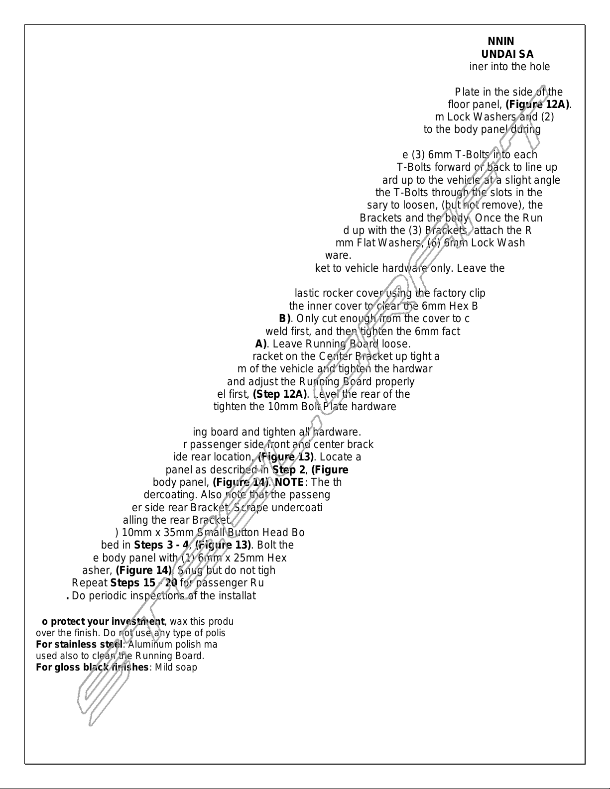
ALUMINUM VIEWPOINT RUNNING BOARDS
2013 HYUNDAI SANTA FE
13. Insert (1) 10mm x 35mm Small Button Head Bolt Plate with (1) 10mm Plastic Retainer into the hole in
the bottom of the body panel as described in Step 2, (Figures 12A & 12B).
14. Select the driver side Rear Bracket. Slide the Bracket over the Low Profile Bolt Plate in the side of the
body panel first, (Figures 11B), then up and over the Bolt Plate in the bottom floor panel, (Figure 12A).
Bolt the Bracket to the (2) Bolt Plates with (2) 10mm Flat Washers, (2) 10mm Lock Washers and (2)
10mm Hex Nuts. IMPORTANT: Do not push the Low Profile Bolt Plate into the body panel during
installation. Snug but do not tighten hardware at this time.
15. Carefully unwrap the driver side Running Board. From the front, slide (3) 6mm T-Bolts into each
channel in the bottom of the Running Board, (Figure 15). Slide the T-Bolts forward or back to line up
with the slots in the (3) Mounting Brackets. Hold the Running Board up to the vehicle at a slight angle
and gently push it into position against the rocker panel. Insert the T-Bolts through the slots in the
Brackets but leave loose at this time. NOTE: It may be necessary to loosen, (but not remove), the
Bracket hardware to insert the Running Board between the Brackets and the body. Once the Running
Board is in the approximate position and the T-Bolts lined up with the (3) Brackets, attach the Running
Board to the Mounting Brackets with the included (6) 6mm Flat Washers, (6) 6mm Lock Washers and
(6) 6mm Hex Nuts, (Figure 16). Do not tighten hardware.
16. Return to the Front Bracket. Tighten the front Bracket to vehicle hardware only. Leave the Running
Board hardware loose.
17. Move to the Center Bracket and reinstall the plastic rocker cover using the factory clips and hardware. It
may be necessary to trim a small piece from the inner cover to clear the 6mm Hex Bolt attaching the
Center Bracket to the pinch weld, (Step 10B). Only cut enough from the cover to clear the hardware.
Tighten the 6mm bolt through the pinch weld first, and then tighten the 6mm factory hex bolt securing
the Center Bracket to vehicle, (Step 9A). Leave Running Board loose.
18. Push the bent end of the L-Support Bracket on the Center Bracket up tight against the plastic cover to
help hold the cover up to the bottom of the vehicle and tighten the hardware, (Step 10B).
19. Move to the rear Bracket. Level and adjust the Running Board properly and tighten the 10mm Hex Nut
on the bottom of the body panel first, (Step 12A). Level the rear of the running board with the front.
Once properly adjusted, fully tighten the 10mm Bolt Plate hardware on the back of the body pane,
(Step 11B)l.
20. Align and adjust the running board and tighten all hardware.
21. Repeat Steps 2 - 10 for passenger side front and center bracket installation only.
22. Move to passenger side rear location, (Figure 13). Locate and remove the round rubber plug in the
bottom of the body panel as described in Step 2, (Figure 2A). Locate the 6mm threaded hole in the
side of the inner body panel, (Figure 14). NOTE: The threaded hole may be covered with sealing tape
and/or thick undercoating. Also note that the passenger side rear Bracket installs in a different location
than the driver side rear Bracket. Scrape undercoating off of the body panel to locate the threaded hole
before installing the rear Bracket.
23. Insert (1) 10mm x 35mm Small Button Head Bolt Plate into the hole in the bottom of the body panel as
described in Steps 3 - 4, (Figure 13). Bolt the top mount on the Bracket to the threaded hole in the side
of the body panel with (1) 6mm x 25mm Hex Bolt, (1) 6mm Lock Washer and (1) 6mm x 22mm Flat
Washer, (Figure 14). Snug but do not tighten hardware at this time.
24. Repeat Steps 15 - 20 for passenger Running Board installation.
25. Do periodic inspections of the installation to make sure that all hardware is secure and tight.
To protect your investment, wax this product after installing. Regular waxing is recommended to add a protective layer
over the finish. Do not use any type of polish or wax that may contain abrasives that could damage the finish.
For stainless steel: Aluminum polish may be used to polish small scratches and scuffs on the finish. Mild soap may be
used also to clean the Running Board.
For gloss black finishes: Mild soap may be used to clean the Running Board.
Page 3 of 8 4/15/13(DP)
 Loading...