

Steelcraft Automotive 155110 User Manual
VIEWPOINT RUNNING BOARDS
1
Driver side running board
1
8mm Insert Installation Tool
1
Passenger side running board
4
10-1.50mm x 35mm Hex Bolt
1
Driver Front Mounting Bracket
10
10mm x 24mm OD x 2.2mm Flat Washer
1
Passenger Front Mounting Bracket
6
10mm Lock Washer
1
Driver Front Support Bracket
6
10-1.50mm Hex Nut
1
Passenger Front Support Bracket
12
8-1.25mm x 25mm Hex Bolt
1
Driver Center Mounting Bracket
12
8mm Lock Washer
1
Passenger Center Mounting Bracket
12
8mm x 22mm x 2mm Flat Washers
1
Driver Rear Mounting Bracket
12
6-1.0 x 20mm T-Bolts
1
Passenger Rear Mounting Bracket
12
6mm x 22mm OD x 2mm Flat Washer
2
10-1.50mm x 40mm Bolt Plate
12
6mm Lock Washer
2
8-1.25mm Threaded Insert
12
6-1.0mm Hex Nuts
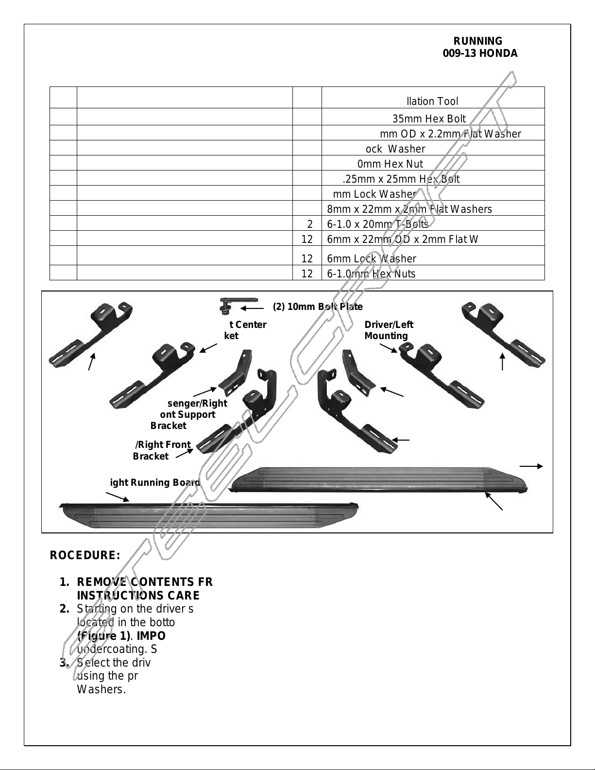
Passenger/Right
Rear Mounting
Bracket
Driver/Left Rear
Mounting
Bracket
Driver/Left Front
Support Bracket
Passenger/Right
Front Support
Bracket
Passenger/Right Front
Mounting Bracket
Driver/Left Front
Mounting Bracket
Rear
Front
Driver/Left Running Board
Passenger/Right Running Board
(2) 10mm Bolt Plate
Passenger/Right Center
Mounting Bracket
Driver/Left Center
Mounting Bracket
2009-13 HONDA PILOT
PARTS LIST:
PROCEDURE:
1. REMOVE CONTENTS FROM BOX. VERIFY ALL PARTS ARE PRESENT. READ
INSTRUCTIONS CAREFULLY BEFORE STARTING INSTALLATION.
2. Starting on the driver side of the vehicle, locate the two factory 8mm threaded holes, one
located in the bottom of the floor panel and the second in the side of the inner body panel,
(Figure 1). IMPORTANT: All factory threaded holes may be covered with rubber plugs or
undercoating. Scrape off any excess undercoating from mounting surfaces.
3. Select the driver side Front Mounting Bracket. Attach the Bracket to the two threaded holes
using the provided (2) 8mm x 25mm Hex Bolts, (2) 8mm Lock Washers and (2) 8mm Flat
Washers. Snug but do not tighten hardware at this time, (Figure 2).
Page 1 of 5 2-13-13(DP)

VIEWPOINT RUNNING BOARDS
2009-13 HONDA PILOT
4. Select (1) 10mm Bolt Plate, (Figure 3). Insert the Bolt Plate into the factory hole in the
bottom of the frame channel, (Figure 4). Rotate the Bolt Plate clock-wise 90-degrees or until
it stops turning. NOTE: To help determine the correct inner mounting hole on the frame to
use, hold the Support Bracket up to the back of the Front Bracket with the inner end lined up
with the hole in the bottom of the frame channel, (Figure 5).
5. Bolt the driver side Support Bracket to the back of the front Mounting Bracket with (2) 10mm
x 35mm Hex Bolts, (4) 10mm Flat Washers, (2) 10mm Lock Washers and (2) 10mm Hex
Nuts, (Figure 5). Next, hang the inner end of the Support Bracket from the previously
installed Bolt Plate using (1) 10mm Flat Washer, (1) 10mm Lock Washer and (1) Hex Nut.
Do not fully tighten hardware at this time.
6. Next, move to the center of the vehicle and locate the (2) 8mm threaded holes located on
the bottom of the floor panel and bottom of the frame channel, (Figure 6). Select the driver
side Center Mounting Bracket, (Figure 7). IMPORTANT: Center and Rear Brackets are
similar but unique. To help identify, the Center Brackets feature a notch cut out of the inner
end of the Bracket, (Figure 7). Attach the Center Bracket to the two threaded holes using
the provided (2) 8mm x 25mm Hex Bolts, (2) 8mm Lock Washers and (2) 8mm Flat
Washers, (Figure 8). Snug but do not tighten hardware at this time.
7. Continue along the side of the vehicle to the rear mounting location. Locate the 8mm
threaded hole in the bottom of the frame channel, (Figure 9). Locate the factory hole in the
bottom of the floor panel. Remove rubber plugs as necessary. NOTE: To determine the
correct mounting holes to use, hold the driver side rear Mounting Bracket up in position
against the factory threaded hole in the end of the frame channel, (Figure 9). Remaining
hole in mounting tab on the bracket will line up with correct factory hole in floor panel.
8. Select the 8mm Threaded Insert Tool, (1) 8mm Threaded Insert, (1) 8mm Flat Washer and
(1) 8mm x 25mm Hex Bolt, (Figure 10). Assemble the tool as pictured in Figure 10. Insert
the assembly into the factory hole. Firmly hold the tool handle and assembly up tight against
the floor panel and tighten the 8mm Hex Bolt until the insert is fully expanded in the hole,
(Figure 11). NOTE: Do not over tighten or a pull out may occur. Once Insert is fully
compressed, remove the bolt and tool from the Insert.
9. Attach the driver side Rear Bracket to the (2) threaded holes with (2) 8mm x 25mm Hex
Bolts, (2) 8mm Lock Washers and (2) 8mm Flat Washers, (Figure 13). Do not tighten
hardware at this time.
10. Select the driver/left side Running Board. Locate the openings cut at the end of the slots on
the bottom of the Running Board, (Figure 14). Insert (3) 6mm T-Bolts into each channel
through the openings. Slide the T-Bolts into the approximate position in line with the (3)
Brackets on the vehicle.
11. Carefully position the Driver/Left Running Board onto the (3) Mounting Brackets. Slide the T-
Bolts into position and through the slots in the Brackets. Attach the Board to the Brackets
with (6) 6mm Flat Washers, (6) 6mm Lock washers and (6) 6mm Hex Nuts, (Figure 15). Do
not tighten hardware at this time.
12. Level and adjust the Running Board and tighten all hardware.
13. Repeat Steps 2 - 12 for the passenger/right Running Board installation.
14. Do periodic inspections to the installation to make sure that all hardware is secure and tight.
To protect your investment, wax this product after installing. Regular waxing is recommended to add a protective
layer over the finish. Do not use any type of polish or wax that may contain abrasives that could damage the finish.
For stainless steel: Aluminum polish may be used to polish small scratches and scuffs on the finish. Mild soap may
be used also to clean the Running Board.
Page 2 of 5 2-13-13(DP)
 Loading...