

Steelcraft Automotive 155090 User Manual
VIEWPOINT RUNNING BOARDS
Front
Front
1
Driver/Left Running Board
2
10mm Lock Washers
1
Passenger/Right Running Board
20
8mm x 25mm Hex Bolts
2
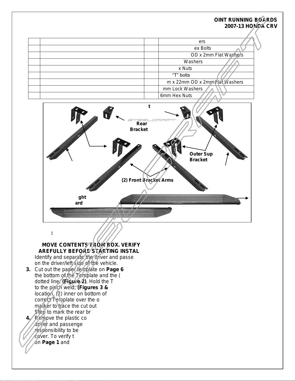
Front Mounting Bracket Arms
28
8mm x 22mm OD x 2mm Flat Washers
2
Rear Mounting Bracket Arms
20
8mm Lock Washers
4
Outer Support Brackets
8
8mm Hex Nuts
1
Driver/Left Rear Inner Support Bracket
8
6mm “T” bolts
1
Passenger/Right Rear Inner Support Bracket
8
6mm x 22mm OD x 2mm Flat Washers
2
10mm x 20mm Hex Bolts
8
6mm Lock Washers
2
10mm x 20mm OD x 2mm Flat Washers
8
6mm Hex Nuts
Driver/Left
R
(2) Front Bracket Arms
Passenger/Right Rear
Inner Support Bracket
Rear Bracket Arm
Rear Bracket Arm
Outer Support
Brackets
Outer Support
Brackets
Driver/Left
Running Board
Passenger/Right
Running Board
Front
Driver/Left Side
Passenger/Right
Side
2007-13 HONDA CRV
PARTS LIST:
PROCEDURE:
1. REMOVE CONTENTS FROM BOX. VERIFY ALL PARTS ARE PRESENT. READ INSTRUCTIONS
CAREFULLY BEFORE STARTING INSTALLATION. CUTTING IS REQUIRED.
2. Identify and separate the driver and passenger side front and rear Mounting Brackets. Start installation
on the driver/left side of the vehicle.
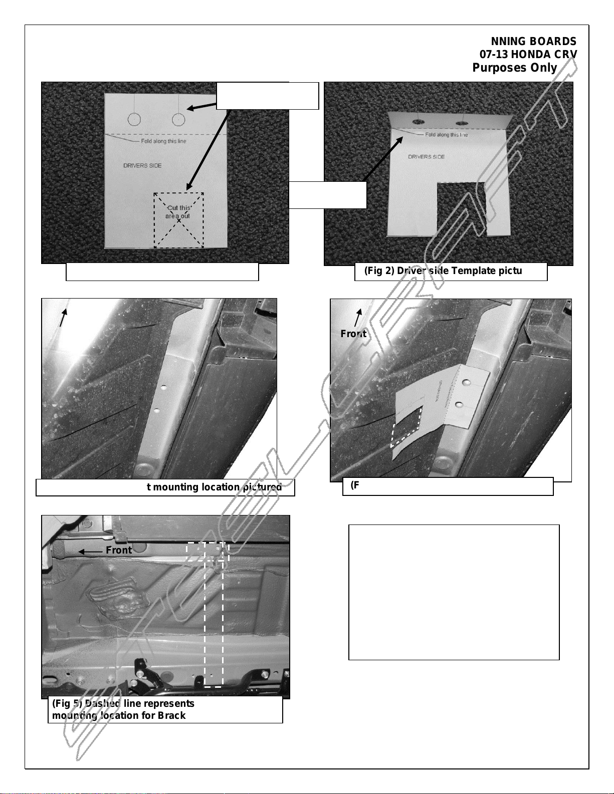
3. Cut out the paper template on Page 6 labeled "Driver Side," (Figure 1). Cut out the square section on
the bottom of the Template and the (2) 8mm holes on the top. Fold the top of the Template up along the
dotted line, (Figure 2). Hold the Template in place over the outer (2) factory 8mm threaded holes next
to the pinch weld, (Figures 3 & 4). IMPORTANT: There are (4) threaded holes at each mounting
location, (2) inner on bottom of frame channel and (2) outer next to pinch weld, (Figure 5). Hold the
correct Template over the outer threaded holes and up against the plastic cover, (Figure 4). Use a
marker to trace the cut out section on the bottom of the Template onto the plastic cover. Repeat this
Step to mark the rear bracket location for cutting.
4. Remove the plastic cover. Cut out the (2) sections as marked. VERY IMPORTANT: The Templates are
driver and passenger side specific and have been provided for reference use only. It is the installer's
responsibility to be absolutely sure that the correct location has been marked before cutting the plastic
cover. To verify the locations before cutting, temporarily assemble the Mounting Brackets as pictured
on Page 1 and check the locations on the cover.
Page 1 of 7 9/14/12 (DP)
VIEWPOINT RUNNING BOARDS
2007-13 HONDA CRV
5. Partially install the plastic cover. IMPORTANT: Attach the cover to the vehicle with the outer, (next to
pinch weld), hardware only. Allow the cover to hang in place from the outer hardware. Do not install
inner hardware at this time.
6. Locate the forward (2) 8mm threaded holes in the floor panel, (See Step 3, Fig. 3). Select (1) Outer
Support Bracket. Bolt the Bracket to the threaded holes with (2) 8mm Hex Bolts, (2) 8mm Lock
Washers, and (2) 8mm Flat Washers, (Figure 6). Snug but do not fully tighten hardware at this time.
7. Select (1) Front Bracket Arm, (Figure 7). Insert the Bracket Arm through the tabs on the Support
Bracket and into the hole cut out of the plastic cover. Line up the inner end of the Bracket with the rear
threaded hole on the bottom of the frame channel in line with the outer holes, (Figure 8). Attach the
Bracket to the frame channel with (1) 8mm Hex Bolt, (1) 8mm Lock Washer and (1) 8mm Flat Washer.
Bolt the Bracket Arm to the (2) tabs on the Support Bracket with (2) 8mm x 25mm Hex Bolts, (4) 8mm
Flat Washers, (2) 8mm Lock Washers and (2) 8mm Hex Nuts, (Figure 9). NOTE: Mounting tab on
outer Support Bracket will go toward front of vehicle. Do not tighten hardware at this time.
8. Locate the rear (2) 8mm threaded holes in the floor panel, (See Step 3). Select (1) Outer Support
Bracket. Bolt the Bracket to the threaded holes with (2) 8mm Hex Bolts, (2) 8mm Lock Washers, and
(2) 8mm Flat Washers, (Figure 6). Snug but do fully tighten hardware at this time.
9. Next, select the driver side rear Inner Support Bracket and (1) Rear Bracket Arm. Bolt the Support
Bracket to the end of the Arm with (1) 10mm x 20mm Hex Bolt, (1) 10mm Lock Washer and (1) 10mm
Flat Washer, (Figures 9 & 10). Do not tighten at this time.
10. Insert the rear Bracket Arm through the (2) tabs on the Support Bracket and into the hole cut out of the
plastic cover. Line up the tab on the Support Bracket with the rear threaded hole on the bottom of the
frame channel in line with the outer holes, (Figure 10). Attach the Bracket to the frame channel with (1)
8mm Hex Bolt, (1) 8mm Lock Washer and (1) 8mm Flat Washer. Bolt the Bracket Arm to the (2) tabs
on the Support Bracket with (2) 8mm x 25mm Hex Bolts, (4) 8mm Flat Washers, (2) 8mm Lock
Washers and (2) 8mm Hex Nuts, (Figure 11). NOTE: Mounting tab on Support Bracket will go toward
front of vehicle, (Figures 8 & 9). Do not tighten hardware at this time.
11. Select the driver/left side Running Board. Insert (2) 6mm T-Bolts into each slot and slide them down the
channel in the bottom of the Board and into approximate position in line with the Brackets, (Figure 12).
12. Carefully position the Driver/Left Running Board onto the (2) Mounting Brackets. Slide the T-Bolts into
position and through the slots in the Brackets, (Figure 13). Attach the Board to the Brackets with (4)
6mm Flat Washers, (4) 6mm Lock washers and (4) 6mm Hex Nuts, (Figure 14). Do not tighten
hardware at this time.
13. Level and adjust the Running Board and tighten all hardware.
14. Leave the plastic cover completely loose and fully tighten the hardware bolting the Brackets to the
vehicle. NOTE: It may be necessary to remove the Brackets and plastic cover if the cover requires
additional cutting. Leave plastic cover loose at this time. Cover will not be reinstalled until after the
Running Board has been installed, aligned and then all hardware tightened. Cover must be loose to
access inner hardware.
15. Once all Bracket hardware has been completely tightened, reinstall the plastic cover with the factory
hardware. NOTE: Depending on model year, additional trimming may be required around the Brackets
to clear the inside of the plastic cover near the frame channel.
16. Repeat Steps 2 – 15 for passenger/right side Running Board installation.
17. Do periodic inspections to the installation to make sure that all hardware is secure and tight.
To protect your investment, wax this product after installing. Regular waxing is recommended to add a
protective layer over the finish. Do not use any type of polish or wax that may contain abrasives that could
damage the finish.
For stainless steel: Aluminum polish may be used to polish small scratches and scuffs on the finish. Mild
soap may be used also to clean the Running Board.
Page 2 of 7 9/14/12 (DP)
Front
Front
Front
Driver Side Installation Pictured Without Plastic Cover for Instruction Purposes Only
With the plastic cover in place, hold
the paper template (Driver side
pictured) over the (2) threaded holes
next to the pinch weld. Use a marker
to trace the square cut out section on
the template. Remove cover. Use a
utility knife or hacksaw to carefully
cut out this section. Check the
clearance between the Bracket and
the cover often for proper fit
(Fig 3) Driver side front mounting location pictured
(Fig 1) Driver side Template pictured
(Fig 2) Driver side Template pictured
(Fig 4) Front driver side location pictured
Cut out square and
(2) round holes
Fold up along
dashed line
(Fig 5) Dashed line represents driver side front
mounting location for Bracket assembly
Page 3 of 7 9/14/12 (DP)
VIEWPOINT RUNNING BOARDS
2007-13 HONDA CRV
 Loading...