

Page 1
VIEWPOINT RUNNING BOARDS
1
Driver Side Running Board
4
10mm Plastic Retainer
1
Passenger Side Running Board
2
10mm x 50mm “T” Bolts (Rear Bracket only)
1
Driver Side Front Mounting Bracket
2
10mm x 35mm Button Head Bolt Plates
1
Passenger Side Front Mounting Bracket
4
10mm x 25mm Hex Bolts
1
Driver Side Center Mounting Bracket
2
10mm x 34mm x 3mm Large Flat Washers
1
Passenger Side Center Mounting Bracket
6
10mm x 27mm x 3mm STD Flat Washers
1
Driver Side Rear Mounting Bracket
4
10mm Lock Washers
1
Passenger Side Rear Mounting Bracket
4
10-1.5mm Serrated Flange Nuts Gr 8.8
1
10mm Insert Installing Tool
12
6mm x 20 mm “T” Bolts (Running Board)
1
6mm Insert Installing Tool
4
6-1.0mm x 25mm Hex Head Bolts
4
10-1.5mm Threaded Inserts
16
6mm x 22mm OD x 2mm Flat Washers
3
6-1.0mm Threaded Inserts
16
6mm Lock Washers
12
6mm Hex Nuts
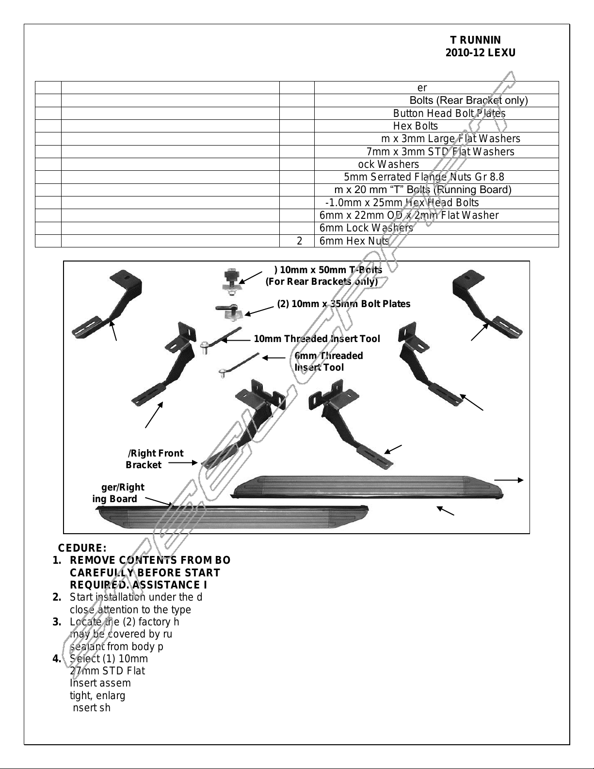
Driver/Left Rear
Mounting Bracket
Driver/Left Front
Mounting Bracket
Driver/Left
Center Bracket
Passenger/Right
Rear Mounting
Bracket
Passenger/Right
Center Bracket
Passenger/Right Front
Mounting Bracket
(2) 10mm x 50mm T-Bolts
(For Rear Brackets only)
(2) 10mm x 35mm Bolt Plates
10mm Threaded Insert Tool
Driver/Left
Running Board
Passenger/Right
Running Board
Front
6mm Threaded
Insert Tool
2010-12 LEXUS RX350
PARTS LIST:
PROCEDURE:
1. REMOVE CONTENTS FROM BOX. VERIFY ALL PARTS ARE PRESENT. READ INSTRUCTIONS
CAREFULLY BEFORE STARTING INSTALLATION. CUTTING IS REQUIRED. DRILLING IS
REQUIRED. ASSISTANCE IS RECOMMENDED.
2. Start installation under the driver side front of the vehicle. Remove the plastic covers, (Fig. 1). Pay
close attention to the type and location of all factory hardware for reinstallation.
3. Locate the (2) factory holes in the inside wall of the floor panel, (Fig. 1). NOTE: The mounting locations
may be covered by rubber plugs, sealant and/or undercoating. IMPORTANT: Scrape any excess
sealant from body panel before installing any and all Brackets.
4. Select (1) 10mm Threaded Insert, (1) 10mm Insert Tool, (1) 10mm x 25mm Hex Bolt and (1) 10mm x
27mm STD Flat Washer. Assemble the Threaded Insert as pictured in Figure 2. Insert the Threaded
Insert assembly into the forward, larger hole in the inner body panel, (Fig. 4). NOTE: If Insert fits too
tight, enlarge hole by drilling with a 1/2" drill bit. IMPORTANT: Be careful not to enlarge hole too much.
Insert should fit snug in hole and lip on Insert should be against sheet metal surface.
Page 1 of 8 10/23/12 (DP)
Page 2

VIEWPOINT RUNNING BOARDS
2010-12 LEXUS RX350
5. Hold the assembly in place by the handle on the Tool and apply pressure to keep the Insert in the hole.
Tighten the Hex Bolt on the assembly until Insert is fully compressed/expanded and locked in place,
(Fig. 3). NOTE: Do not over tighten or Insert failure or pull out may occur. Once the Threaded Insert is
fully compressed, remove the Hex Bolt and Tool. Repeat Steps 4 & 5 for all Threaded Insert
installations.
6. Next, assemble (1) 6mm Threaded Insert and Tool as previously described. Insert the 6mm Threaded
Insert assembly into the small hole 4" back from the first Insert installation in Steps 4 & 5.
Driver/left front Bracket installation:
Remove the 6mm factory hex bolt holding the bracket for the plastic cover up to the bottom of the
frame channel, (Fig. 4). Select the driver side front Mounting Bracket. Slide the mounting tab on
the Bracket under the factory bracket. Bolt the Mounting Bracket to the 10mm Threaded Insert with
(1) 10mm x 25mm Hex Bolt, (1) 10mm Lock Washer, (1) 10mm x 27mm STD flat washer. Attach
the Bracket to the 6mm Threaded Insert with (1) 6mm x 25mm Hex Bolt, (1) 6mm Lock Washer
and (1) 6mm Flat Washer. Replace the factory 6mm bolt with (1) 6mm x 25mm Hex Bolt, (1) 6mm
Lock Washer and (1) 6mm Flat Washer, (Fig. 5). Snug but do not fully tighten hardware at this
time.
Passenger/right front Bracket installation:
Repeat Steps 2 - 6 to install the Inserts for the passenger side front Bracket but note that there
is no 6mm hex bolt on the bottom of the body panel, (Fig. 6 & 7). Install the passenger side
front Bracket as previously described in driver side installation, (Fig. 8). Mark the location of the
bottom mounting tab onto the bottom of the floor panel. Drill a 3/8" hole in the marked location.
Install (1) 6mm Threaded Insert. Secure the bottom tab to the Threaded Insert with (1) 6mm x
25mm Hex Bolt, (1) 6mm Lock Washer and (1) 6mm Flat Washer, (Fig. 9).
7. Move to the center mounting location. Remove the plastic plug on the inside of the frame channel
approximately 31-1/2" back along the floor panel from the front wheel opening, (Fig. 10B). Select (1)
10mm Button Head Bolt Plate and (1) 10mm Plastic Retainer, (Fig. 10A). Partially thread the Retainer
onto the Bolt Plate. Insert the Bolt Plate into the factory hole, (Fig. 10B). Thread the Retainer down
tight against the sheet metal. IMPORTANT: The Plastic Retainer is designed to prevent the Bolt Plate
from falling into the body cavity and to aid Bracket installation.
Driver/left center Bracket installation:
Remove the plastic plug on the bottom of the floor panel. Select (1) 10mm Threaded Insert and
assemble the insert tool, (Fig. 10B). Push the Insert into the hole in the bottom of the floor panel
and install as previously described. NOTE: It may be necessary to enlarge hole slightly as
described in Step 4.
Hold the driver side center Mounting Bracket up in place and attach it to the Bolt Plate with (1)
10mm STD Flat Washer and (1) 10mm Flange Nut. Secure the Bracket to the 10mm Threaded
Insert with (1) 10mm x 25mm Hex Bolt, (1) 10mm Lock Washer and (1) 10mm STD Flat Washer,
(Fig. 11). Snug but do not fully tighten hardware at this time.
Passenger/right center Bracket installation:
Repeat Step 7 to install the passenger side Center Bracket but note that there is no factory hole
in the bottom of the frame channel, (similar to front Bracket install in Step 6). Bolt the Bracket to
the Bolt Plate as previously described with the Bracket tight against the bottom of the frame
channel, (Fig. 12). Mark the slot location onto the bottom of the channel, (Fig. 13). Remove the
Center Bracket. Drill a 1/2" hole in the marked location. Install the 10mm Threaded Insert into
the hole as previously described, (Fig. 14). Reinstall the Bracket. Bolt the Bracket to the 10mm
Insert with (1) 10mm x 25mm Hex Bolt, (1) 10mm Lock Washer and (1) 10mm STD Flat
Washer, (Fig. 11). Snug but do not tighten hardware.
8. Move to the rear mounting location and locate the large oval hole in the floor panel, (Fig. 15). Remove
rubber plug. Select (1) 10mm T-Bolt and (1) 10mm Plastic Retainer, (Fig. 16A). Partially thread the
Retainer onto the T-Bolt. Insert the T-Bolt into the oval hole in the floor panel and rotate Bolt 90degrees so that the Block is across the oval hole, (Fig. 16B). Thread the Retainer down until it is tight
against the floor panel, (Fig. 17). Select the driver side rear Mounting Bracket. Secure the Bracket to
the T-Bolt with (1) 10mm x 34mm Large Flat Washer and (1) 10mm Flange Nut, (Fig. 18). Snug but do
not fully tighten hardware at this time.
Page 2 of 8 10/23/12 (DP)
Page 3
VIEWPOINT RUNNING BOARDS
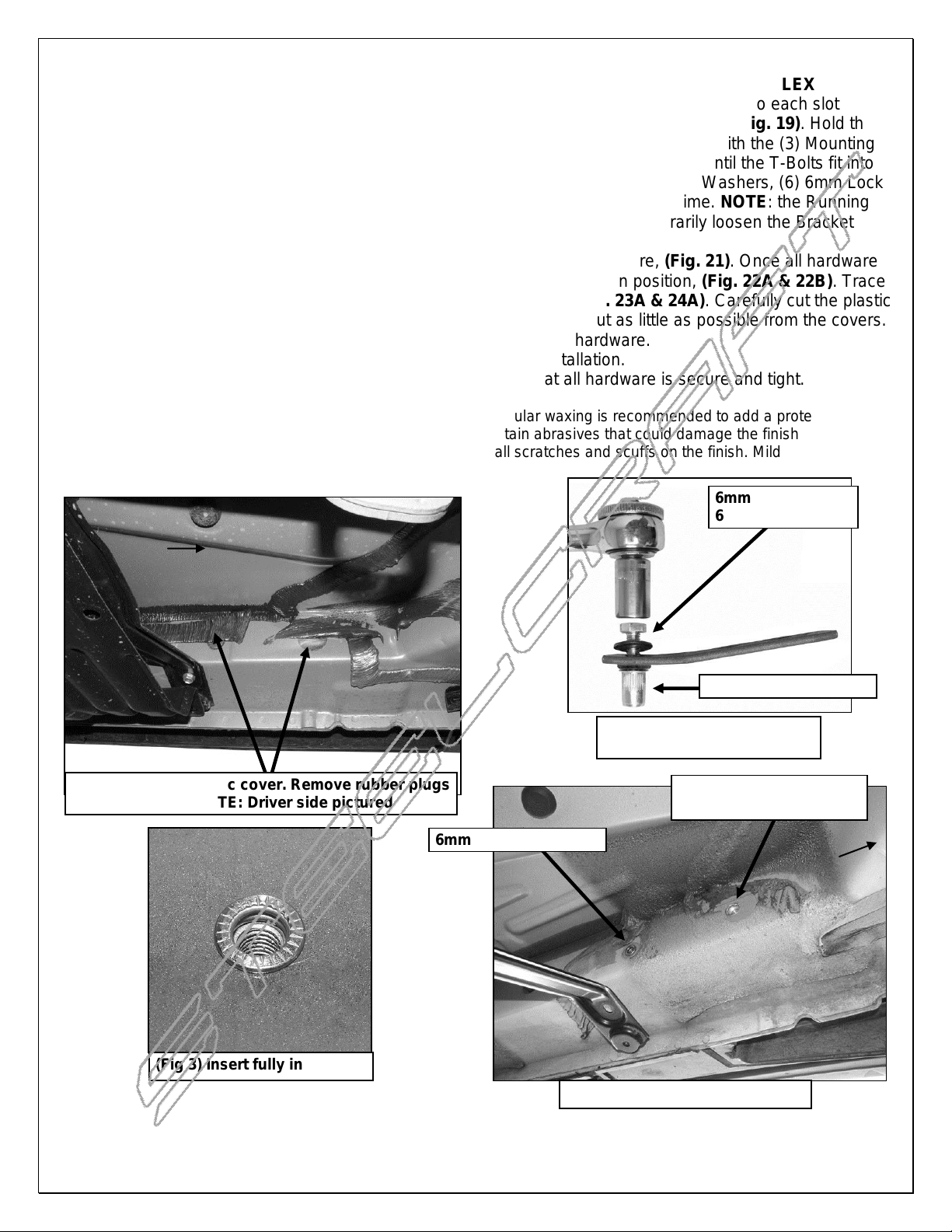
(Fig 1) Remove plastic cover. Remove rubber plugs
in factory holes. NOTE: Driver side pictured
(Fig 3) Insert fully installed
Front
(Fig 2) 6mm Threaded Insert
Tool assembly pictured
6mm Hex Bolt
6mm Flat Washer
6mm Threaded Insert
6mm Threaded Insert
10mm Threaded Insert.
Drilling may be required
Front
(Fig 4) Driver side front pictured
2010-12 LEXUS RX350
9. Carefully unwrap and select the driver side Running Board. Insert (3) 6mm T-Bolts into each slot in the
end of the channels, (3 T-Bolts per channel), on the bottom of the Running Board, (Fig. 19). Hold the
Running Board up in approximate position and slide the T-Bolts down to line up with the (3) Mounting
Brackets. Tilt the Board up at a slight angle and push back against the vehicle until the T-Bolts fit into
the slots on the Brackets. Secure the Board to the Brackets with (6) 6mm Flat Washers, (6) 6mm Lock
Washers and (6) 6mm Hex Nuts, (Fig. 20). Do not tighten hardware at this time. NOTE: the Running
Board is designed to fit close to the vehicle. It may be necessary to temporarily loosen the Bracket
hardware and tilt the Brackets downward to insert the Running Board.
10. Level and adjust the Running Board as desired and tighten all hardware, (Fig. 21). Once all hardware
has been tightened, hold the plastic covers removed in Step 2, up in position, (Fig. 22A & 22B). Trace
the location of the front and center Brackets onto the covers, (Fig. 23A & 24A). Carefully cut the plastic
covers to clear the Brackets, (Fig. 23B & 24B). IMPORTANT: Cut as little as possible from the covers.
Reinstall the plastic covers with factory hardware. Tighten all hardware.
11. Repeat Steps 2 – 10 for passenger side Running Board installation.
12. Do periodic inspections to the installation to make sure that all hardware is secure and tight.
To protect your investment, wax this product after installing. Regular waxing is recommended to add a protective layer
over the finish. Do not use any type of polish or wax that may contain abrasives that could damage the finish.
For stainless steel: Aluminum polish may be used to polish small scratches and scuffs on the finish. Mild soap may be
used also to clean the Running Board.
Page 3 of 8 10/23/12 (DP)
Page 4

(Fig 9) Passenger side front
mounting location pictured
Front
6mm Hex Bolt
6mm Lock Washer
6mm Flat Washer
10mm Hex Bolt
10mm Lock Washer
10mm STD Flat Washer
(Fig 6) Passenger/Right side front pictured
Fig 5
6mm Threaded Insert
Fig 7
Fig 8
6mm Threaded Insert
Front
Front
Front
Front
Bolt passenger side front Bracket in
place. Mark location of slot on
bottom of frame channel to drill for
6mm Threaded Insert (see Fig 7)
10mm Threaded Insert.
Drilling may be required
NOTE: To insert a 10mm
Threaded Insert into the
large factory hole, check
for fit and/or use 1/2"
drill bit as necessary
VIEWPOINT RUNNING BOARDS
2010-12 LEXUS RX350
Page 4 of 8 10/23/12 (DP)
Page 5

Remove plastic plugs on side
and bottom of frame channel
Front
(Fig 10A) Use Plastic Retainer to hold Bolt
Plate in place during Bracket installation
(Fig 10B) Driver side center
mounting location pictured
(Fig 6A) 10mm x 35mm Bolt Plate
Front
10mm Hex Bolt
10mm Lock Washer
10mm x 27mm STD
Flat Washer
Front
(Fig 13) Passenger/Right side center
Bracket mounting location pictured
(Fig 11) Driver side center
Mounting Bracket pictured
10mm Flat Washer
10mm Flange Nut
10mm Flat Washer
10mm Flange Nut
(Fig 12) Passenger side center
mounting location pictured
Front
10mm Threaded Insert
VIEWPOINT RUNNING BOARDS
2010-12 LEXUS RX350
Page 5 of 8 10/23/12 (DP)
Page 6

VIEWPOINT RUNNING BOARDS
10mm Bolt Plate
10mm Plastic Retainer
Remove rubber plug
Rear
(Fig 14) Passenger/Right side center
Bracket mounting location pictured
(Fig 15) Driver side rear mounting location
(Fig 17) T-Bolt with Plastic Retainer
(Fig 16B) Insert T-Bolt then rotate
90-degrees to go across oval hole
Front
(Fig 16A) 10mm T-Bolt
Rear
Rear
10mm Threaded Insert
2010-12 LEXUS RX350
Page 6 of 8 10/23/12 (DP)
Page 7

VIEWPOINT RUNNING BOARDS
6mm x 22mm Flat Washers
6mm Lock Washers
6mm Hex Nuts
Insert T-Bolts into
channel and slide
into position
Rear
Front
(Fig 18) Driver side rear Mounting Bracket
Fig 20
(Fig 21) Driver side complete installation
10mm Flat Washer
10mm Flange Nut
(Fig 22A) Hold plastic cover up in
position to determine area to cut from
cover. Driver side middle cover pictured
Front
Fig 19
Front
2010-12 LEXUS RX350
Page 7 of 8 10/23/12 (DP)
Page 8

VIEWPOINT RUNNING BOARDS
Front
(Fig 23A) Driver side front cover pictured
(Fig 23B) Cut cover only enough to clear
Bracket. Cut shown for example only
(Fig 24A) Driver side middle cover
(Fig 24B) Cut cover only enough to clear
Bracket. Cut shown for example only
(Fig 22B) Hold plastic cover up in
position to determine area to cut from
cover. Driver side front cover pictured
Front
Front
Front
Front
2010-12 LEXUS RX350
Page 8 of 8 10/23/12 (DP)
 Loading...