

Steelcraft Automotive 114000 User Manual
VIEWPOINT RUNNING BOARDS
1
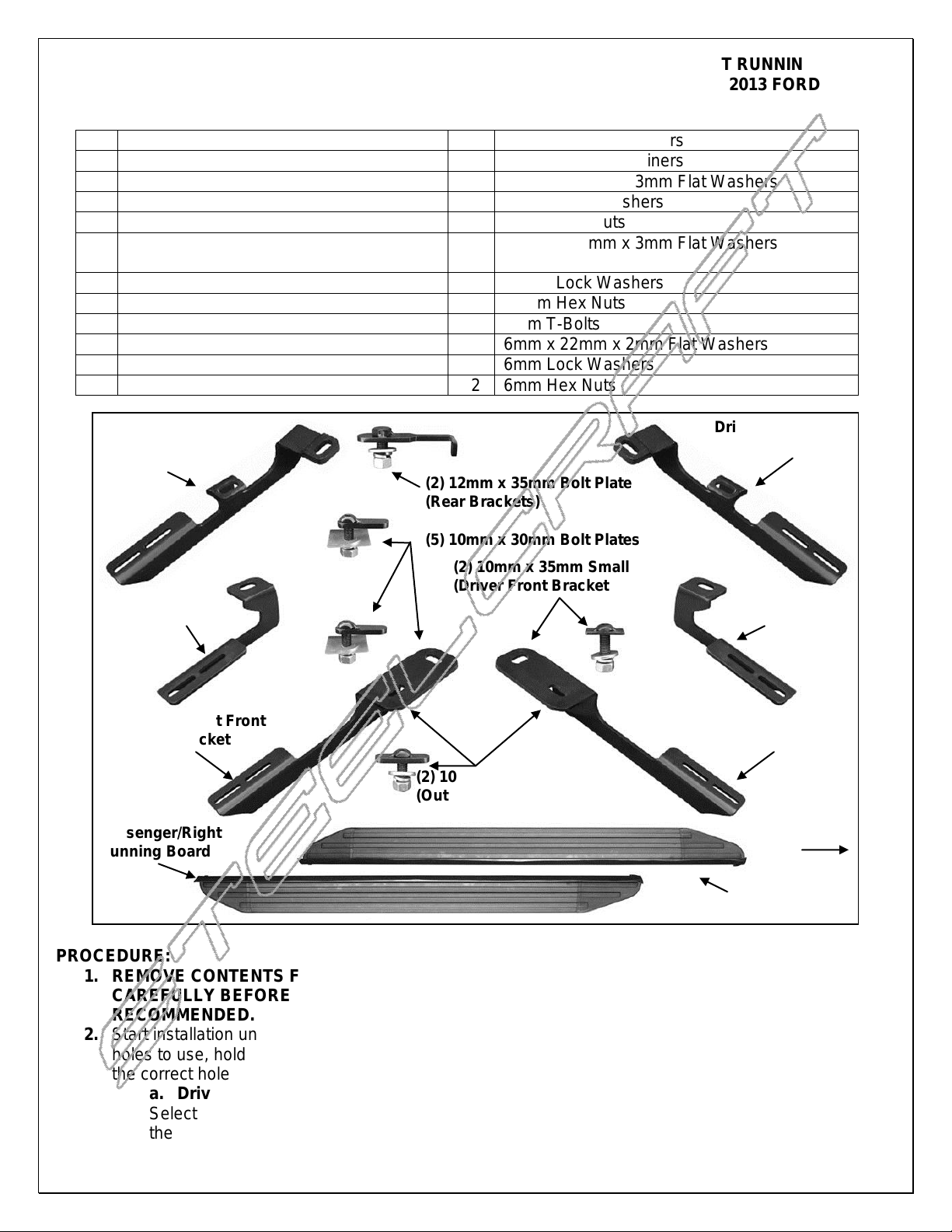
Driver/Left Running Board
2
12mm Plastic Retainers
1
Passenger/Right Running Board
8
10mm Plastic Retainers
1
Driver/Left Front Mounting Bracket
2
12mm x 32mm x 3mm Flat Washers
1
Passenger/Right Front Mounting Bracket
2
12mm Lock Washers
1
Driver/Left Center Mounting Bracket
2
12mm Hex Nuts
1
Passenger/Right Center Mounting
Bracket
8
10mm x 27mm x 3mm Flat Washers
1
Driver/Left Rear Mounting Bracket
8
10mm Lock Washers
1
Passenger/Right Rear Mounting Bracket
8
10mm Hex Nuts
2
12mm x 35mm Special Bolt Plate (rear)
12
6mm T-Bolts
5
10mm x 30mm Button Head Bolt Plates
12
6mm x 22mm x 2mm Flat Washers
2
10mm x 30mm T-bolts (Both front outer)
12
6mm Lock Washers
1
10mm x 35mm T-bolt (Driver front inner)
12
6mm Hex Nuts
Driver/Left Rear
Mounting Bracket
Driver/Left Front
Mounting Bracket
Driver/Left
Center Bracket
Passenger/Right
Rear Mounting
Bracket
Passenger/Right
Center Bracket
Passenger/Right Front
Mounting Bracket
(2) 12mm x 35mm Bolt Plate
(Rear Brackets)
(5) 10mm x 30mm Bolt Plates
(2) 10mm x 35mm Small T-Bolt
(Driver Front Bracket Only)
(2) 10mm x 30mm Large T-Bolt
(Outer Front Brackets)
Driver/Left
Running Board
Passenger/Right
Running Board
Front
2013 FORD ESCAPE
PARTS LIST:
PROCEDURE:
1. REMOVE CONTENTS FROM BOX. VERIFY ALL PARTS ARE PRESENT. READ INSTRUCTIONS
CAREFULLY BEFORE STARTING INSTALLATION. CUTTING IS REQUIRED. ASSISTANCE IS
RECOMMENDED.
2. Start installation under the driver side of the vehicle. NOTE: To help determine the correct mounting
holes to use, hold the front Bracket up in position against the floor panel and line up the Bracket with
the correct holes, (Fig 1).
a. Driver side front Bracket installation:
Select (1) 10mm x 30mm Small T-Bolt and (1) 10mm Plastic Retainer, (Fig. 2A). Partially thread
the Retainer onto the T-Bolt. Insert the T-Bolt into the inner factory oval hole. Rotate the T-Bolt 90-
Page 1 of 7 9/12/12 (DP)

VIEWPOINT RUNNING BOARDS
2013 FORD ESCAPE
degrees so that the plate is across the slot. Thread the Retainer down until it is tight against the
floor panel. The Retainer is designed to help hold the T-Bolt in place during Bracket installation.
Next, insert (1) 10mm x 35mm Large T-Bolt with (1) Plastic Retainer into the outer oval hole in the
floor panel next to the pinch weld as previously described, (Fig. 2B & 3).
b. Passenger side front Bracket installation:
IMPORTANT-Repeat the previous Step 2a for passenger side Bracket installation but note that the
inner mounting tab on the front Bracket will use (1) 10mm x 30mm Button Head Bolt Plate, (same
bolt plate as used on center and rear Brackets), inserted into a round hole instead of the 10mm
Small T-Bolt, (Fig. 2B, 4 & 5).
3. Hang the driver side Front Bracket from the T-Bolts with (2) 10mm Flat Washers, (2) 10mm Lock
Washers and (2) 10mm Hex Nuts, (Fig. 6). Do not tighten hardware at this time.
4. Release the plastic clips holding the lower plastic rocker panel cover to the bottom of the body, (Fig. 7).
5. Measure 40" back from the bottom corner of the wheel opening to locate the correct factory hole under
the plastic rocker cover for the center Bracket, (Fig. 8). Pull plastic out to access the hole, (Fig. 10).
Partially thread (1) 10mm Plastic Retainer onto (1) 10mm x 30mm Button Head Bolt Plate, (Fig. 9).
Insert Bolt Plate, (Fig. 10), into the round hole and thread the Retainer down tight against the body.
NOTE: Insert the Center Bracket into the approximate position. Mark the Bracket location on the bottom
edge of the plastic cover, (Fig. 11). Cut a small slot in the bottom edge of the cover to clear the
Bracket. Bolt the Bracket to the Bolt Plate with (1) 10mm Flat Washer, (1) 10mm Lock Washer and (1)
10mm Hex Nut, (Fig. 12 & 13). Do not tighten hardware at this time.
6. Move to the rear location and remove the plastic cover on the floor panel, (Fig. 14). Locate the small
round hole under the plastic rocker cover, (Fig. 15). Select (1) 10mm x 30mm Bolt Plate and (1) 10mm
Plastic Retainer. Insert the Bolt Plate into the round hole as described in Step 5, (Fig. 16 & 17).
7. Next, locate the large round hole in the floor panel. Insert (1) 12mm x 35mm Bolt Plate into the large
round hole and out the smaller hole toward the front, (Fig. 18 & 19). Next, Slide the driver side Rear
Bracket under the plastic rocker cover and over the (2) Bolt Plates, (Fig. 20). Secure the Bracket to the
outer 10mm Bolt Plate with (1) 10mm Flat Washer, (1) 10mm Lock Washer and (1) 10mm Hex Nut.
Attach the Bracket to the Larger 12mm Bolt Plate with (1) 12mm Flat Washer, (1) 12mm Lock Washer
and (1) 12mm Hex Nut. Do not tighten hardware at this time.
8. Hold the plastic cover removed in Step 6, up in position. Trace the location of the rear Bracket onto the
cover, (Fig. 21). Carefully cut the plastic cover to clear the Bracket, (Fig. 22A & 22B). IMPORTANT:
Cut as little as possible from the cover. Do not cut off the mounting area for the factory hardware.
Reinstall the plastic cover and all plastic clips holding the bottom of the rocker cover to the body panel.
9. Carefully unwrap the Running Board and select the driver side. Insert (6) 6mm T-Bolts into the slots in
the end of the channels, (3 Bolts per channel), on the bottom of the Running Board, (Fig. 23). Hold the
Running Board up in approximate position and slide the T-Bolts down to line up with the Mounting
Brackets. Tilt the Board up at a slight angle and push back against the vehicle until the T-Bolts fit into
the slots on the Brackets. VERY IMPORTANT: The front Bracket is very close to the slots in the frontend of the Board for the T-Bolts. Loosen the Front Bracket and push it toward the rear of vehicle so that
the Bracket is at a slight angle to clear the slots for the T-Bolts, (Fig. 24). Secure the Board to the
Brackets with (6) 6mm Flat Washers, (6) 6mm Lock Washers and (6) 6mm Hex Nuts, (Fig. 25). Do not
tighten hardware at this time. NOTE, the Running Board is designed to fit close to the vehicle. It may be
necessary to loosen the Bracket hardware and tilt the Brackets downward to insert the Running Board.
10. Level and adjust the Running Board and tighten all hardware.
11. Repeat Steps 2 – 10 for passenger side Running Board installation. NOTE: See specific passenger
side front Bracket installation info in Step 2b.
12. Do periodic inspections to the installation to make sure that all hardware is secure and tight.
To protect your investment, wax this product after installing. Regular waxing is recommended to add a protective layer
over the finish. Do not use any type of polish or wax that may contain abrasives that could damage the finish.
For stainless steel: Aluminum polish may be used to polish small scratches and scuffs on the finish. Mild soap may be
used also to clean the Running Board.
Page 2 of 7 9/12/12 (DP)

VIEWPOINT RUNNING BOARDS
(Fig 1) Driver side front
mounting location pictured
(Fig 3) Driver side pictured
Front
(Fig 5) Use 10mm x 30mm Bolt Plate for
passenger side inner location (same bolt
plate used on center and rear brackets)
(Fig 2A) Small 10mm x 35mm T-Bolt
for driver side inner front bracket only
Front
(Fig 4) Passenger side front
mounting location pictured
(Fig 2B) Large 10mm x 30mm T-Bolt
for driver and passenger side outer
location on front brackets only
2013 FORD ESCAPE
Driver/Left Side Installation Pictured
Page 3 of 7 9/12/12 (DP)
 Loading...