

Steelcraft Automotive 113900 User Manual
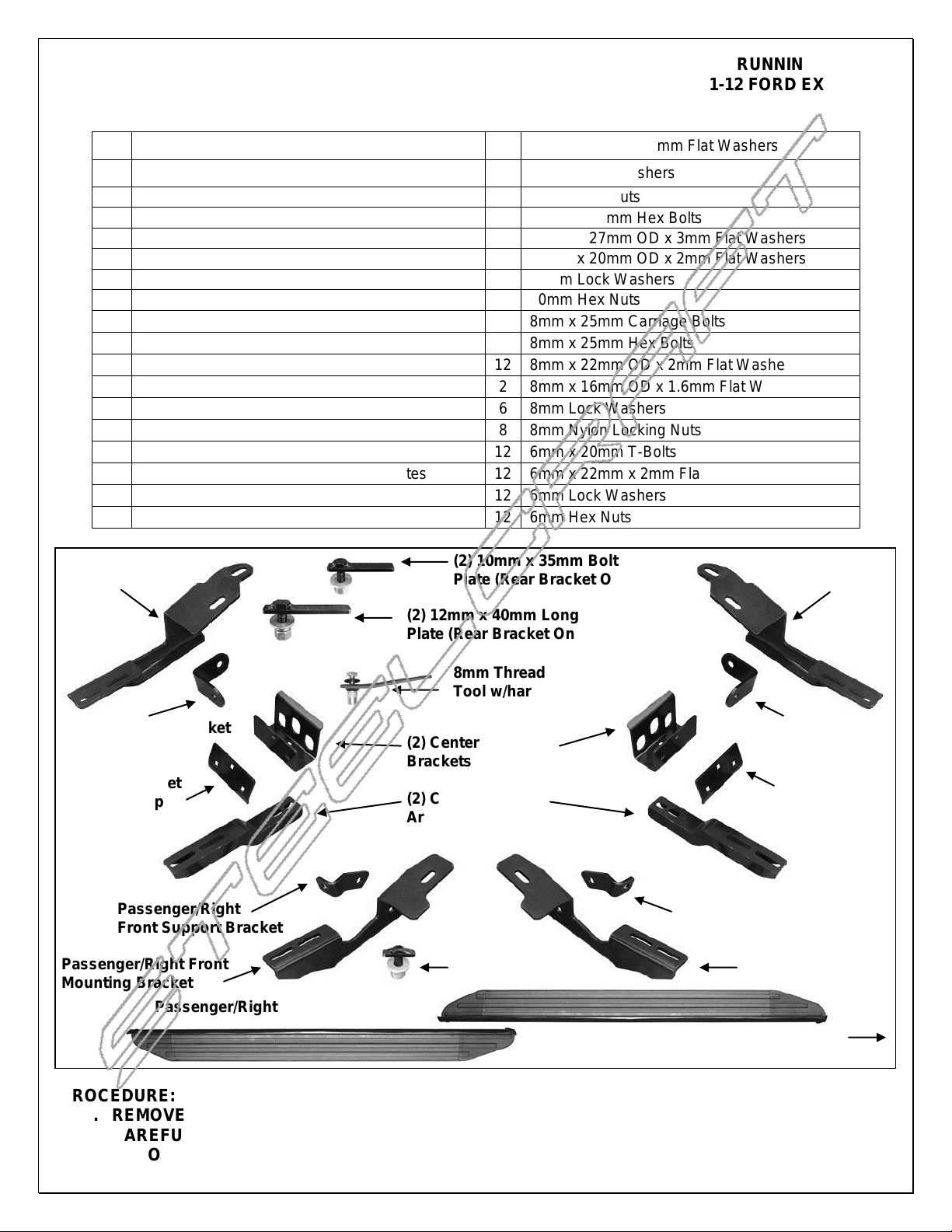
PARTS LIST:
1
Driver/Left Running Board
4
12mm x 32mm x 3mm Flat Washers
1
Passenger/Right Running Board
4
12mm Lock Washers
1
Driver/Left Front Mounting Bracket
4
12mm Hex Nuts
1
Passenger/Right Front Mounting Bracket
4
10mm x 30mm Hex Bolts
1
Driver/Left Front Support Bracket
2
10mm x 27mm OD x 3mm Flat Washers
1
Passenger/Right Front Support Bracket
8
10mm x 20mm OD x 2mm Flat Washers
2
Center Mounting Brackets
6
10mm Lock Washers
2
Center Bracket Arms
6
10mm Hex Nuts
2
Center Bracket Clamps
8
8mm x 25mm Carriage Bolts
1
Driver/Left Rear Mounting Bracket
6
8mm x 25mm Hex Bolts
1
Passenger/Right Rear Mounting Bracket
12
8mm x 22mm OD x 2mm Flat Washers
2
Rear Support Brackets
2
8mm x 16mm OD x 1.6mm Flat Washers
1
8mm Threaded Insert Tool
6
8mm Lock Washers
6
8mm Threaded Inserts
8
8mm Nylon Locking Nuts
2
12mm x 40mm Long Bolt Plates
12
6mm x 20mm T-Bolts
2
12mm x 35mm Button Head T-Bolt Plates
12
6mm x 22mm x 2mm Flat Washers
2
10mm x 35 Long Bolt Plates
12
6mm Lock Washers
12
6mm Hex Nuts
Driver/Left Rear
Mounting Bracket
Rear Support Bracket
Driver/Left Front
Mounting Bracket
Driver/Left Front
Support Bracket
Passenger/Right
Rear Mounting
Bracket
Rear Support Bracket
Passenger/Right
Front Support Bracket
Passenger/Right Front
Mounting Bracket
(2) 10mm x 35mm Bolt
Plate (Rear Bracket Only)
(2) 12mm x 40mm Long Bolt
Plate (Rear Bracket Only)
(2) 12mm x 35mm
"T" Bolt Plate
Passenger/Right Running Board
Driver/Left Running Board
Front
(2) Center Bracket
Arms
Center Bracket
Outer Clamp
(2) Center Mounting
Brackets
Center Bracket
Outer Clamp
8mm Threaded Insert
Tool w/hardware
VIEWPOINT ALUMINUM RUNNING BOARDS
2011-12 FORD EXPLORER
PROCEDURE:
1. REMOVE CONTENTS FROM BOX. VERIFY ALL PARTS ARE PRESENT. READ INSTRUCTIONS
CAREFULLY BEFORE STARTING INSTALLATION. DRILLING IS REQUIRED. ASSISTANCE IS
RECOMMENDED.
Page 1 of 7 10/10/12 (DP)

VIEWPOINT ALUMINUM RUNNING BOARDS
VERY IMPORTANT! Be very careful and drill slowly through the pinch weld to avoid damaging the
outer rocker panel cover.
NOTE: Any cutting or drilling tool may break or shatter. Government regulations require safety
glasses & equipment at all times when cutting or drilling.
2011-12 FORD EXPLORER
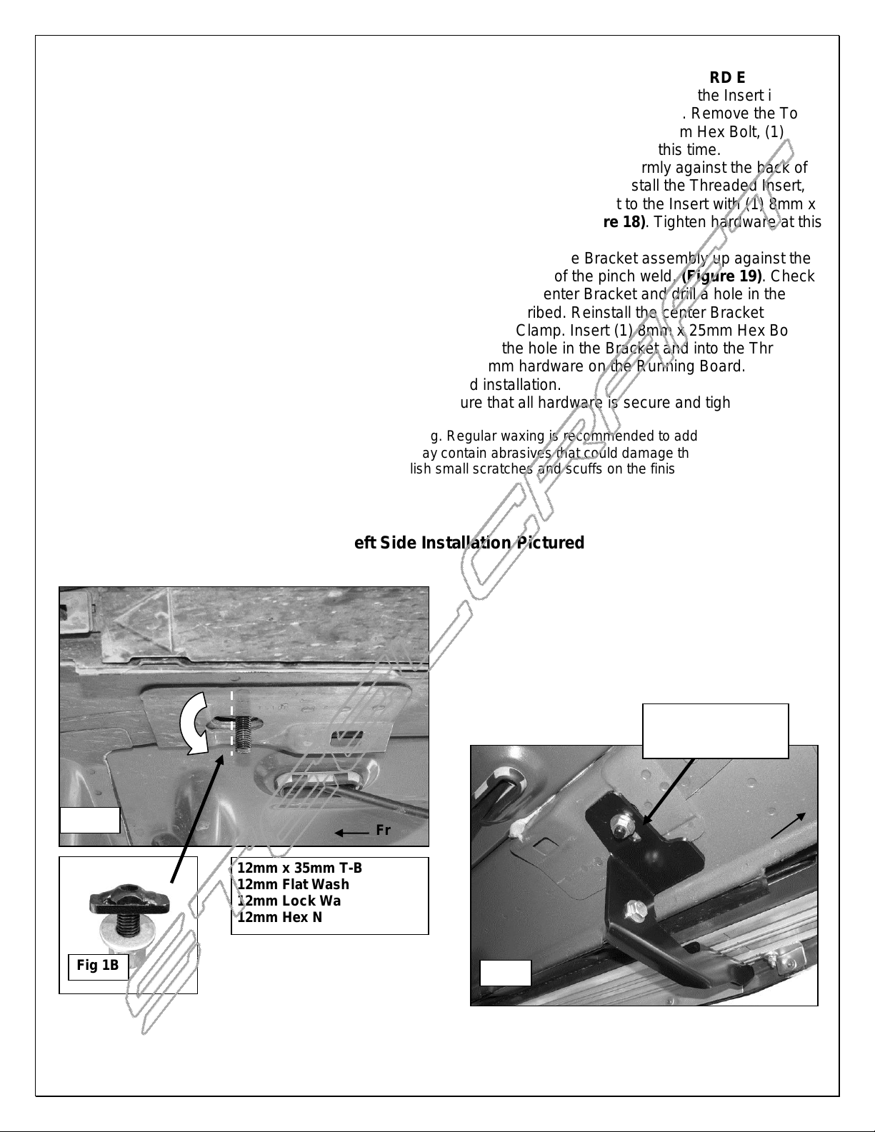
2. Start installation under the driver side of the vehicle. Select (1) 12mm x 35mm Small T-Bolt Plate and
insert it into the factory oval hole in the floor panel, (Figures 1A & 1B). Rotate the Bolt Plate 90-
degrees so that the plate is across the oval hole. Select the driver side front Mounting Bracket. Hang
the Bracket from the Bolt Plate with (1) 12mm Flat Washer, (1) 12mm Lock Washer and (1) 12mm Hex
Nut, (Figure 2). NOTE: Make sure that the mounting flange on the front Bracket is lined up properly
with the indent in the floor panel. The front Mounting Bracket must sit flat against the floor panel. Do not
tighten hardware at this time.
3. Select the driver side front Support Bracket, (Figure 3A). Bolt the Support Bracket to the back of the
front Bracket with (1) 10mm x 30mm Hex Bolt, (2) 10mm x 20mm STD Flat Washers, (1) 10mm Lock
Washer and (1) 10mm Hex Nut, (Figure 3B). Line up the mounting tab on the Support Bracket with the
back of the pinch weld. Do not tighten hardware at this time.
4. Select (1) center Mounting Bracket, Clamp and Arm. Bolt the Arm to the bottom of the center Bracket
with (2) 8mm Carriage Bolts, (1) 8mm x 22mm Large Flat Washer (outer), (1) 8mm x 16mm STD Flat
Washer (inner), and (2) 8mm Nylon Lock Nuts, (Figure 4).
5. Bolt the Clamp Plate to the outside of the center Bracket with (2) 8mm Carriage Bolts (insert through
Plate and the Bracket), (2) 8mm x 22mm Large Flat Washers and (2) 8mm Nylon Lock Nuts, (Figure
5). Do not tighten hardware at this time.
6. IMPORTANT: Select a location for the center Bracket along the pinch weld, mid way between the front
and rear Brackets where the seam is as flat as possible, (Figure 6). Do not install the Bracket over any
of the drip channels in the pinch weld. Once an appropriate location has been found, slide the outer
Clamp Plate and Bracket over the pinch weld with the back part of the Bracket tight against the floor
panel, (Figure 7). Tighten the (2) 10mm Lock Nuts to tighten the Clamp on the pinch weld, (Figure 8).
Do not fully tighten at this time.
7. Move toward the rear location. Locate the oval and round holes in the floor panel toward the rear of the
vehicle, (Figure 9A). Insert (1) 10mm x 35mm Bolt Plate into the round hole, (Figure 9B). Insert (1)
12mm x 40mm Long Bolt Plate into the oval hole next to the pinch weld, (Figure 9C). Rotate the 12mm
Bolt Plate 90-degrees so that the plate is across the oval hole.
8. Position the Rear Mounting Bracket over the (2) Bolt Plates. Secure the Bracket to the 12mm Bolt Plate
with (1) 12mm Flat Washer, (1) 12mm Lock Washer and (1) 12mm Hex Nut, (Figure 10B). Bolt the
Bracket to the 10mm Bolt Plate with (1) 10mm x 27mm OD Large Flat Washer, (1) 10mm Lock Washer
and (1) 10mm Hex Nut. Snug hardware but do not tighten at this time.
9. Next, select (1) "L" rear Support Bracket, (Figure 10A). Bolt the Support Bracket to the front facing side
of the rear Mounting Bracket with (1) 10mm x 30mm Hex Bolt, (2) 10mm x 20mm STD Flat Washers
and (1) 10mm Nylon Lock Nut, (Figures 10B). Do not tighten hardware at this time.
10. Select the driver side Running Board. From the front end of the Board, slide (3) 6mm T-Bolts into each
channel on the bottom of the Board, (Figure 11). Slide the T-Bolts into place in line with the (3)
Brackets and place the Board onto the Brackets. Attach the T-Bolts to the Brackets with (6) 6mm Flat
Washers, (6) 6mm Lock Washers and (6) 6mm Hex Nuts. Snug but do not tighten hardware.
11. Level and adjust the Running Board and tighten the Bracket to Bolt Plate hardware only. IMPORTANT:
Do not tighten the front and rear Support Bracket hardware at this time.
12. Return to the driver side front Bracket and Support Bracket. Hold the front Support Bracket firmly
against the back of the pinch weld. Mark the mounting hole location onto the back of the pinch weld,
(Figure 12).
13. Check the Sidebar for level before proceeding. Carefully drill this location with a 7/16" drill bit.
CAUTION: Do not drill the hole too close to the bottom edge of the pinch weld. Remove the Support
Bracket.
14. Select (1) 8mm Insert Tool, (1) 8mm Threaded Insert, (1) 8mm x 25mm Hex Bolt and (1) 8mm Flat
Washer. Assemble the Threaded Insert Installation Tool as pictured in Figure 13. Hold the handle and
push the Insert into the drilled hole in the pinch weld. NOTE: Insert must fit snug in hole. If necessary,
use a small hammer to carefully tap the Insert into the hole until the rim on the insert is flush against the
Page 2 of 7 10/10/12 (DP)
pinch weld. Firmly hold the tool handle and tighten the Hex Bolt in the Tool to expand the Insert in the
Fig 1A
Fig 2
12mm Flat Washer
12mm Lock Washer
12mm Hex Nut
Front
Fig 1B
Front
12mm x 35mm T-Bolt Plate
12mm Flat Washer
12mm Lock Washer
12mm Hex Nut
hole. Continue until threads are pulled up to the top of the Insert, (Figures 14 & 17). Remove the Tool
and hardware. Bolt the Support Bracket to the Threaded Insert with (1) 8mm x 25mm Hex Bolt, (1)
8mm Flat Washer and (1) 8mm Lock Washer, (Figure 15). Tighten hardware at this time.
15. Move to the driver side rear Mounting Bracket. Hold the "L" Support Bracket firmly against the back of
the pinch weld. Repeat Steps 10 - 14 to mark and drill the pinch weld and install the Threaded Insert,
(Figures 16 & 17). Reinstall the Support Bracket. Bolt the Support Bracket to the Insert with (1) 8mm x
25mm Hex Bolt, (1) 8mm Flat Washer and (1) 8mm Lock Washer, (Figure 18). Tighten hardware at this
time. Tighten the front and rear Bracket hardware only at this time.
16. Move to the center Bracket. Loosen the (2) clamp bolts and push the Bracket assembly up against the
floor panel. Mark the location of the mounting hole onto the back of the pinch weld, (Figure 19). Check
the Running Board alignment before proceeding. Remove the center Bracket and drill a hole in the
pinch weld and install the Threaded Insert as previously described. Reinstall the center Bracket
assembly and snug but do not tighten the 8mm Bolts in the Clamp. Insert (1) 8mm x 25mm Hex Bolt,
(1) 8mm Flat Washer and (1) 8mm Lock Washer through the hole in the Bracket and into the Threaded
Insert, (Figure 20). Tighten all hardware including the 6mm hardware on the Running Board.
17. Repeat Steps 2-16 for passenger/right Running Board installation.
18. Do periodic inspections to the installation to make sure that all hardware is secure and tight.
To protect your investment, wax this product after installing. Regular waxing is recommended to add a protective layer
over the finish. Do not use any type of polish or wax that may contain abrasives that could damage the finish.
For stainless steel: Aluminum polish may be used to polish small scratches and scuffs on the finish. Mild soap may be
used also to clean the Running Board.
VIEWPOINT ALUMINUM RUNNING BOARDS
2011-12 FORD EXPLORER
Driver/Left Side Installation Pictured
Page 3 of 7 10/10/12 (DP)
 Loading...