

Steelcraft Automotive 103800 User Manual
VIEWPOINT RUNNING BOARD
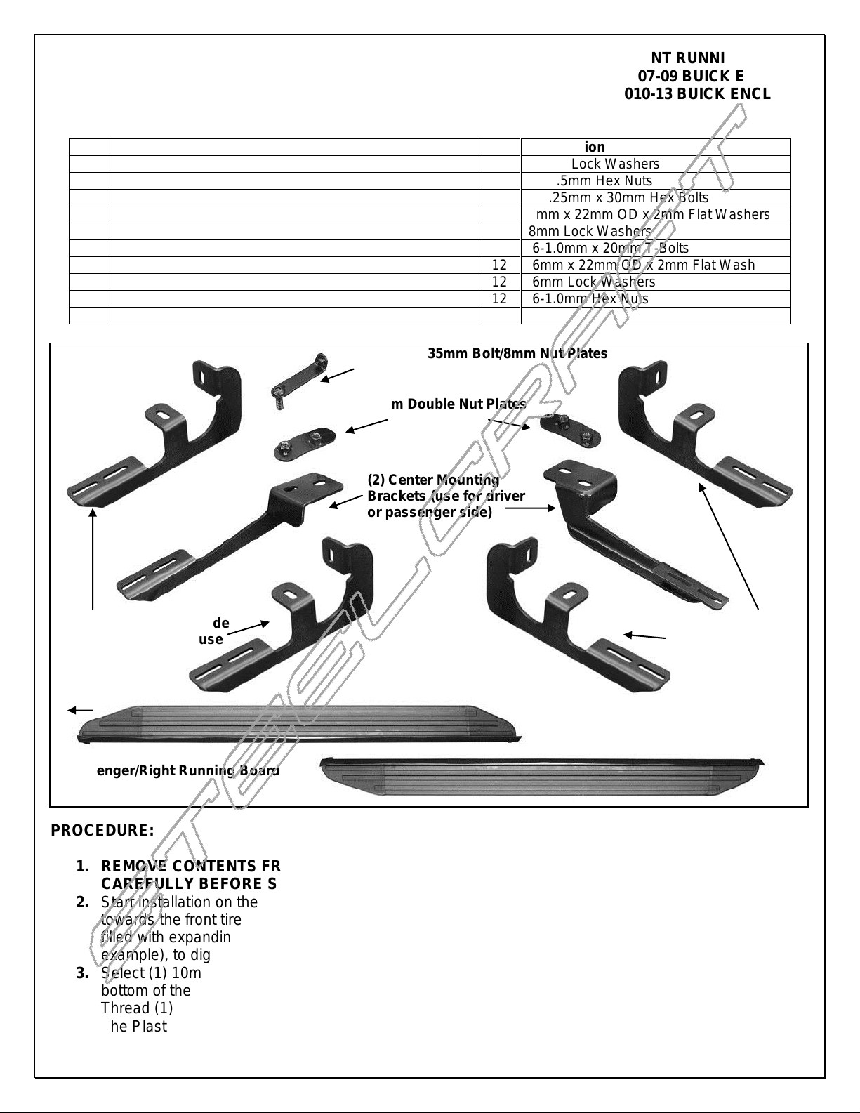
Qty
Description
Qty
Description
1
Driver/Left Running Board
8
10mm Lock Washers
1
Passenger/Right Running Board
4
10-1.5mm Hex Nuts
2
Driver/Left Mounting Brackets (front & rear same)
4
8-1.25mm x 30mm Hex Bolts
2
Passenger/Right Mounting Brackets (front & rear same)
4
8mm x 22mm OD x 2mm Flat Washers
2
Center Mounting Brackets (driver & pass same)
4
8mm Lock Washers
2
10-1.50mm Double Nut Plates
12
6-1.0mm x 20mm T-Bolts
4
10mm x 35mm L-Bolt/8mm Nut Plates
12
6mm x 22mm OD x 2mm Flat Washers
4
10mm Plastic Retainers
12
6mm Lock Washers
4
10-1.50mm x 35mm Hex Bolts
12
6-1.0mm Hex Nuts
8
10mm x 27mm OD x 3mm Flat Washers
(2) Driver/Left Side
Mounting Brackets
(use front or rear)
(2) Passenger/Right Side
Mounting Brackets (use
front or rear)
(2) Center Mounting
Brackets (use for driver
or passenger side)
(2) 12mm Double Nut Plates
Passenger/Right Running Board
Driver/Left Running Board
Front
(4) 10mm x 35mm Bolt/8mm Nut Plates
07-13 CHEVY TRAVERSE/GMC ACADIA/07-10 SATURN OUTLOOK/07-09 BUICK ENCLAVE
(EXCL. ACADIA DENALI, 2010-13 BUICK ENCLAVE)
PARTS LIST:
PROCEDURE:
1. REMOVE CONTENTS FROM BOX. VERIFY ALL PARTS ARE PRESENT. READ INSTRUCTIONS
CAREFULLY BEFORE STARTING INSTALLATION.
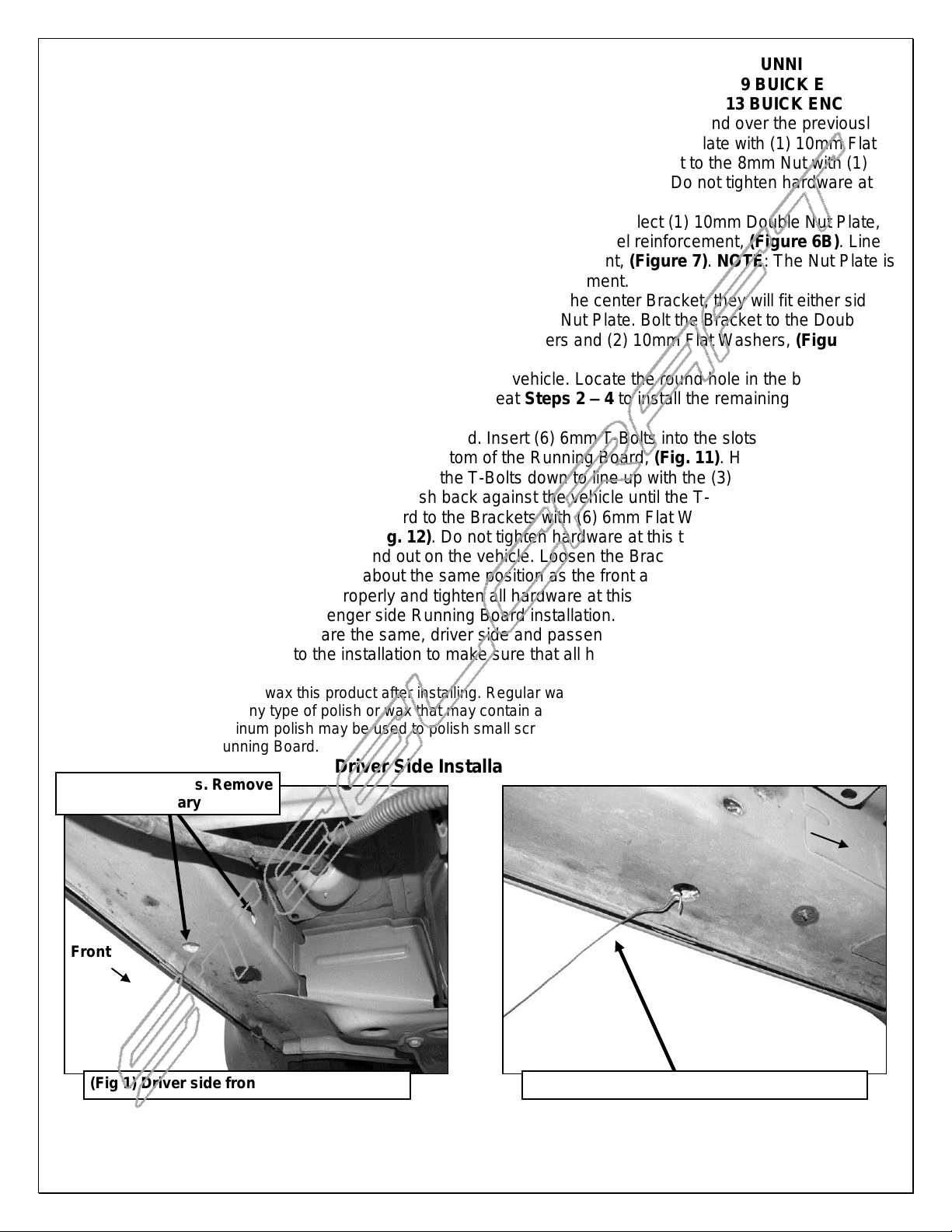
2. Start installation on the driver side. Locate the factory holes in the bottom and inside of the floor panel
towards the front tire opening, (Figure 1). IMPORTANT: On some vehicles, the body panel may be
filled with expanding foam insulation. Use a long flat blade screwdriver or heavy wire, (coat hanger for
example), to dig out the foam to provide clearance for the L-Bolt/Nut Plates, (Figure 2).
3. Select (1) 10mm L-Bolt/Nut Plate, (Figure 3A). Insert the bent end with the 8mm nut into the hole in the
bottom of the floor panel, (Figure 3B). Line up the hex nut with the hole in the side of the floor panel.
Thread (1) 10mm Plastic Retainer onto the 10mm Bolt end of the Bolt/Nut Plate, (Figure 3B). NOTE:
The Plastic Retainer is provided to help hold the Bolt/Nut Plate in position during Bracket installation.
Page 1 of 5 3/5/13 (DP)
VIEWPOINT RUNNING BOARD
(Fig 1) Driver side front mounting location
(Fig 2) Use wire to pull foam from floor panel
Use these (2) holes. Remove
foam as necessary
Front
Front
07-13 CHEVY TRAVERSE/GMC ACADIA/07-10 SATURN OUTLOOK/07-09 BUICK ENCLAVE
(EXCL. ACADIA DENALI, 2010-13 BUICK ENCLAVE)
4. Select (1) driver side Mounting Bracket. Position the Bracket up to the vehicle and over the previously
installed 10mm Bolt/Nut Plate, (Figure 4). Attach the Bracket to the Bolt/Nut Plate with (1) 10mm Flat
Washer, (1) 10mm Lock Washer and (1) 10mm Hex Nut. Attach the Bracket to the 8mm Nut with (1)
8mm x 30mm Hex Bolt, (1) 8mm Lock Washer and (1) 8mm Flat Washer. Do not tighten hardware at
this time.
5. Move along the floor panel to the center of the vehicle, (Figure 5). Select (1) 10mm Double Nut Plate,
(Figure 6A). Insert the Nut Plate into the large hole in the floor panel reinforcement, (Figure 6B). Line
up the threaded hole with the single small hole in the reinforcement, (Figure 7). NOTE: The Nut Plate is
offset to line up with the offset holes in the floor panel reinforcement.
6. Select (1) Center Bracket. NOTE: There is no left or right to the center Bracket, they will fit either side.
Line up the (2) holes in the Center Bracket with the Double Nut Plate. Bolt the Bracket to the Double
Nut Plate with (2) 10mm Hex Bolts, (2) 10mm Lock Washers and (2) 10mm Flat Washers, (Figure 8).
Leave hardware loose at this time.
7. Continue along the floor panel toward the rear of the vehicle. Locate the round hole in the bottom of the
floor panel as described in Step 2, (Figure 9). Repeat Steps 2 – 4 to install the remaining driver side
Bracket in the rear location, (Fig. 10).
8. Carefully un-wrap the driver side Running Board. Insert (6) 6mm T-Bolts into the slots in the end of the
channels, (3 T-Bolts per channel), on the bottom of the Running Board, (Fig. 11). Hold the Running
Board up in approximate position and slide the T-Bolts down to line up with the (3) Mounting Brackets.
Tilt the Board up at a slight angle and push back against the vehicle until the T-Bolts fit into the slots in
the Brackets. Secure the Running Board to the Brackets with (6) 6mm Flat Washers, (6) 6mm Lock
Washers and (6) 6mm Hex Nuts, (Fig. 12). Do not tighten hardware at this time. NOTE: The Center
Bracket has a little adjustment in and out on the vehicle. Loosen the Bracket and slide the Center
Bracket in or outward until it is in about the same position as the front and rear Brackets.
9. Level and adjust the Sidebar properly and tighten all hardware at this time.
10. Repeat Steps 2 – 9 for passenger side Running Board installation. IMPORTANT: The Center Bracket
and Double Nut Plate used are the same, driver side and passenger side.
11. Do periodic inspections to the installation to make sure that all hardware is secure and tight.
To protect your investment, wax this product after installing. Regular waxing is recommended to add a protective layer
over the finish. Do not use any type of polish or wax that may contain abrasives that could damage the finish.
For stainless steel: Aluminum polish may be used to polish small scratches and scuffs on the finish. Mild soap may be
used also to clean the Running Board.
Driver Side Installation Pictured
Page 2 of 5 3/5/13 (DP)
 Loading...