

Page 1
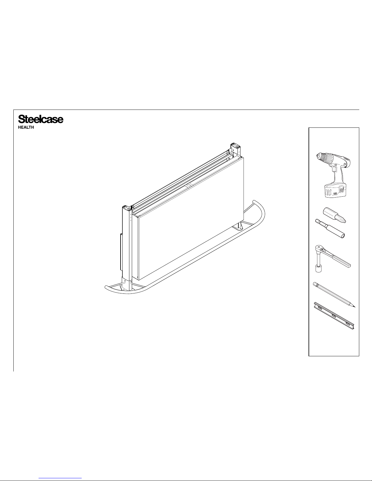
Sync™ Double-Sided Base Units
If you have a problem, question, or request, call
your local dealer, or Steelcase Line 1 at
888.STEELCASE (888.783.3522)
for immediate action by people who want to help you.
(Outside the U.S.A., Canada, Mexico, Puerto Rico,
and the U.S. Virgin Islands, call: 1.616.247.2500)
Or visit our website: www.steelcase.com
©
2018 Steelcase Inc.
Grand Rapids, MI 49501
U.S.A.
Printed in U.S.A.
®
Page 1 of 15
939549943 Rev G
Page 2
Page 2 of 15
939549943 Rev G
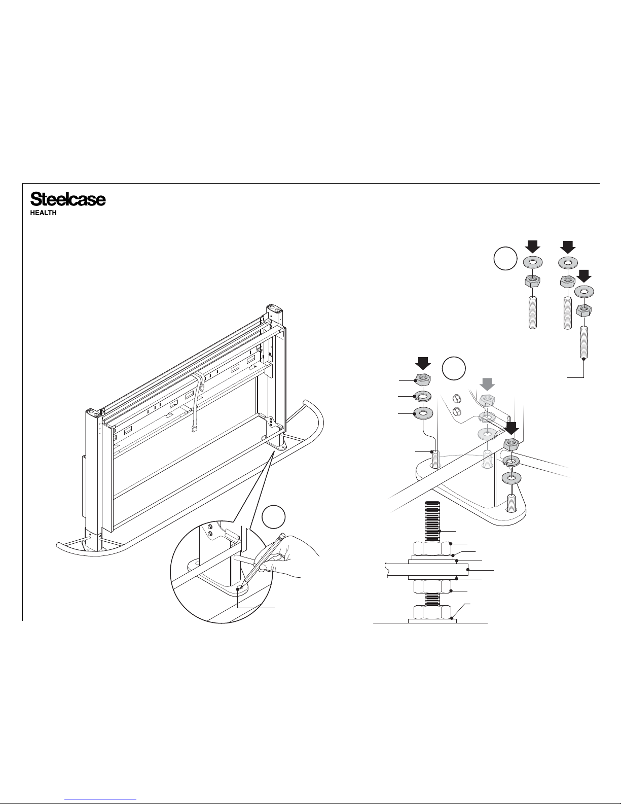
1. Set base unit in place and mark locations for
floor anchors. Set unit aside.
NOTE: Consult the building's Engineer of Record
to specify the correct fasteners for attachment to
the building and to ensure that the building has
adequate structure.
2. Install floor anchors per the fastener
manufacturer's specifications. Leave 2-1/4"
of exposed stud for leveling purposes.
3. Thread a nut, then a washer on each
anchor as shown.
4. Set unit on floor anchors. Plumb and
level base unit using the nuts and washers.
5. Secure the unit with a washer, lock washer
and nut, as shown, to secure the plate. Check for
plumb and level.
1
3
5
CROSS SECTION
OF FINAL ORDER
MARK HOLE
LOCATIONS
NUT
LOCK WASHER
WASHER
FLOOR ANCHOR
NUT
NUT
LOCK WASHER
WASHER
WASHER
FLOOR ANCHOR
PLATE
MFG. RECOMMENDED
NUT / WASHER
FLOOR
ANCHOR
Page 3
Page 3 of 15
939549943 Rev G
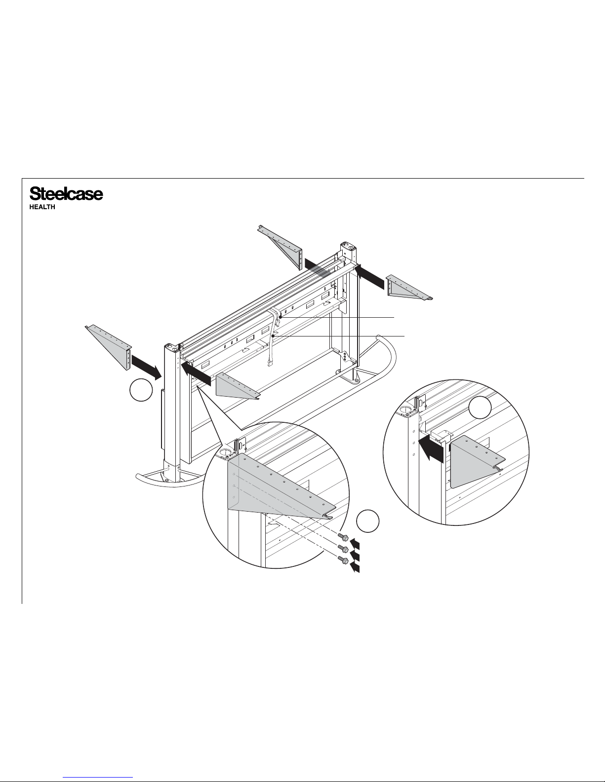
6. Attach the cantilevers for top installation as
shown (6a) and secure to unit using three (3)
bolts per cantilever (6b).
If installing a transaction top, use the smaller
cantilever (6c).
6a
6b
6c
16" LONG STRAP
36" LONG STRAP
Page 4
Page 4 of 15
939549943 Rev G
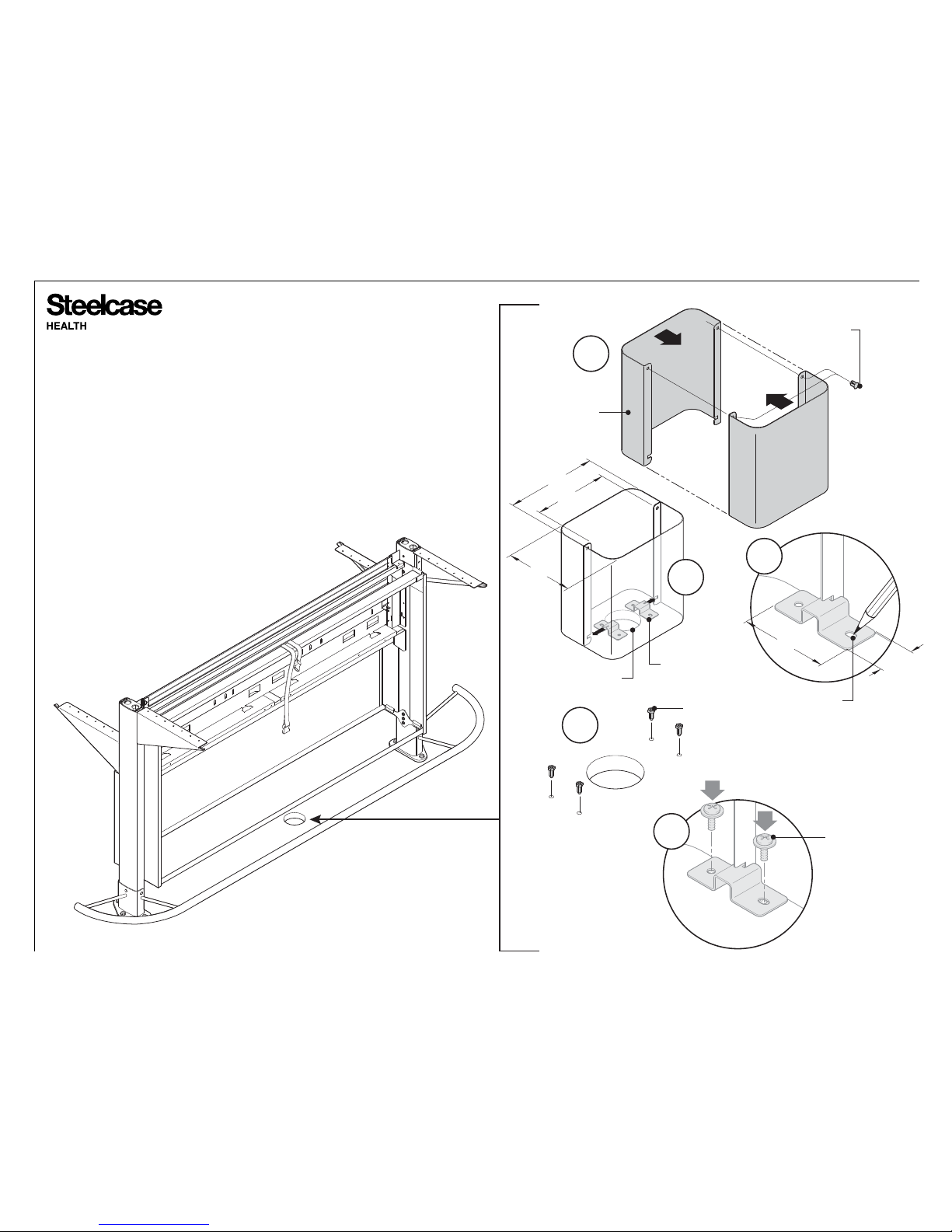
7. After holes for floor power are located, install floor
power cable column.
Place the two sides of cable column next to each other
and snap a push rivet into the top two holes (7a). Place
each cable column floor clip as shown (7b). Mark each
hole on each cable column floor clip (7c). Remove cable
column floor clips and cable columns. Drill 3/8" x 5/8"
deep holes and install floor anchors per manufacturer's
specifications (7d).
8. Position cable column floor clips and cable
columns back into place. Secure clips to floor by
installing two (2) sems screws (with lock
washer) for each clip.
CABLE COLUMN
FLOOR CLIP
CABLE COLUMN
7a
7b
7c
8
HOLE FOR
FLOOR POWER
7d
PUSH RIVET
1-1/16"
2-1/2"
11-7/8”
10-1/2”
5-13/16”
FLOOR ANCHOR
MARK HOLE
LOCATIONS
SEMS SCREW (WITH
LOCK WASHER)
Page 5
Page 5 of 15
939549943 Rev G
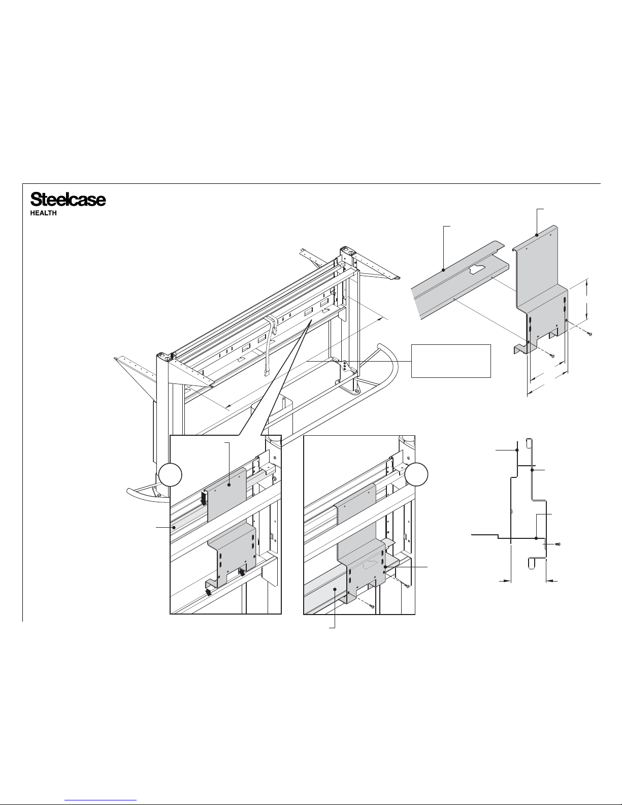
9. Lower multipurpose bracket into place, as shown.
10. Secure multipurpose bracket to upper support with
self-tapping screws. Attach cable tray to multipurpose
bracket with screws, as shown.
NOTE: J-boxes or fasteners are not supplied and
can be installed later. Multipurpose bracket has
mounting holes for standard J-boxes.
9
10
5-1/2"
6-1/2"
CABLE TRAY
MULTIPURPOSE
BRACKET
UPPER SUPPORT
WELDMENT
MULTIPURPOSE
BRACKET
2-11/16"
INSIDE FACEPLATE
TO MULTIPURPOSE
BRACKET
CABLE TRAY
MULTIPURPOSE
BRACKET
FACEPLATE
NOTE: Blunt J-box screws
not to exceed 1/2" long.
36-3/4", 49-1/4" or 61-3/4"
INSIDE MOUNTING
DISTANCE DEPENDING
ON WIDTH OF PRODUCT
CABLE TRAY
MULTIPURPOSE
BRACKET
5-1/2”
Page 6
Page 6 of 15
939549943 Rev G
11. All electrical connections should
be made at this point by a licensed
electrician according to the local
electrical codes (i.e. junction boxes,
receptacles, conduit).
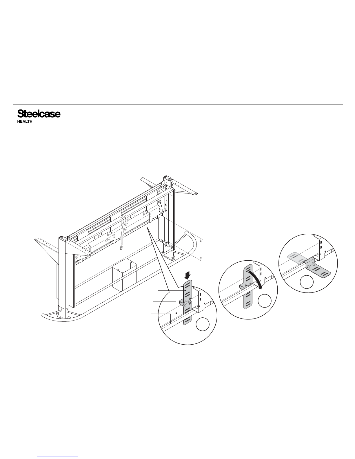
12. Install CPU's by installing the CPU
mount plates. Place each CPU mount
plate between the faceplate and
faceplate support bracket, as shown
(12a). Turn each plate downward (12b)
and into a horizontal position (12c).
12a
12b
12c
12-3/16"
J-BOX MOUNTING
RANGE ON INSIDE
OF LEG
CPU MOUNT
PLATE
FACEPLATE
FACEPLATE
SUPPORT BRACKET
Page 7
Page 7 of 15
939549943 Rev G
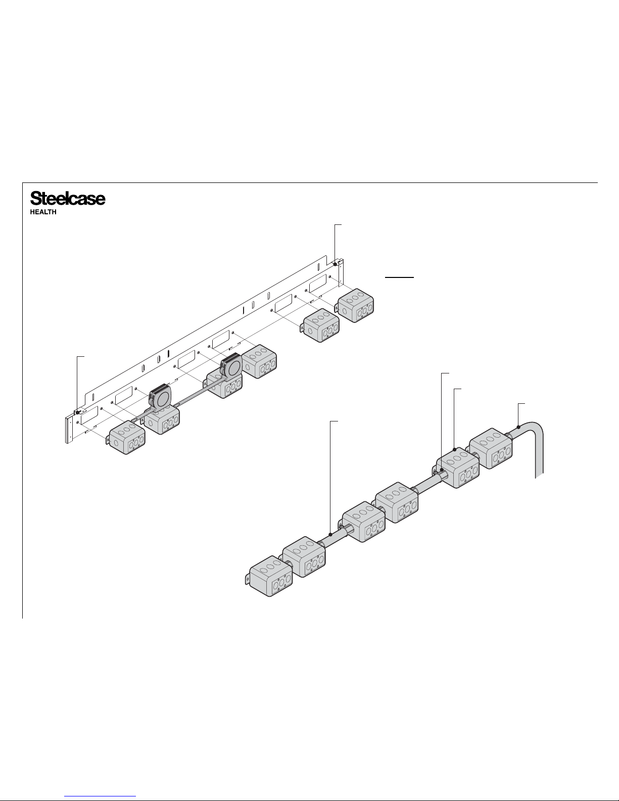
• Align j-boxes to the mounting holes on furniture covers and measure the
distance between the j-boxes to determine conduit length.
• Once conduit length is determined, assemble and wire the entire
assembly in preparation for mounting onto Sync bench. Leave
enough flex conduit length and wire running out of flex conduit to
allow attachment to another j-box mounted on the leg or to the floor.
NOTE: The Sync furniture faceplate is a UL approved faceplate.
Electrician does NOT need to supply.
NOTE: FACEPLATE IS SHOWN REMOVED
FROM BASE UNIT FOR REFERENCE.
DO NOT REMOVE FACEPLATE FROM BASE UNIT.
1/2 or 3/4 CONDUIT
EMT CONNECTOR
3" x 2" x 2-1/2" SWITCH BOX
CONDUIT
GROUNDING TAB
GROUNDING
TAB
Page 8
Page 8 of 15
939549943 Rev G
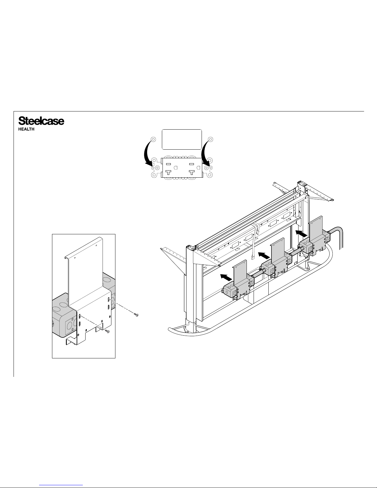
• Position j-box assembly onto the faceplate
cover and mount assembly to the faceplate.
NOTE: The outermost holes are used, with the
supplied stainless steel screws, to attach the
faceplate to the outlets.
• Install the multi-purpose brackets behind the
electrical assembly and attach using blunt screw
from back side of multi-purpose bracket into the
back of the j-boxes.
MOUNTING LOCATION OF
RECEPTACLE TO FACEPLACE
Page 9
Page 9 of 15
939549943 Rev G
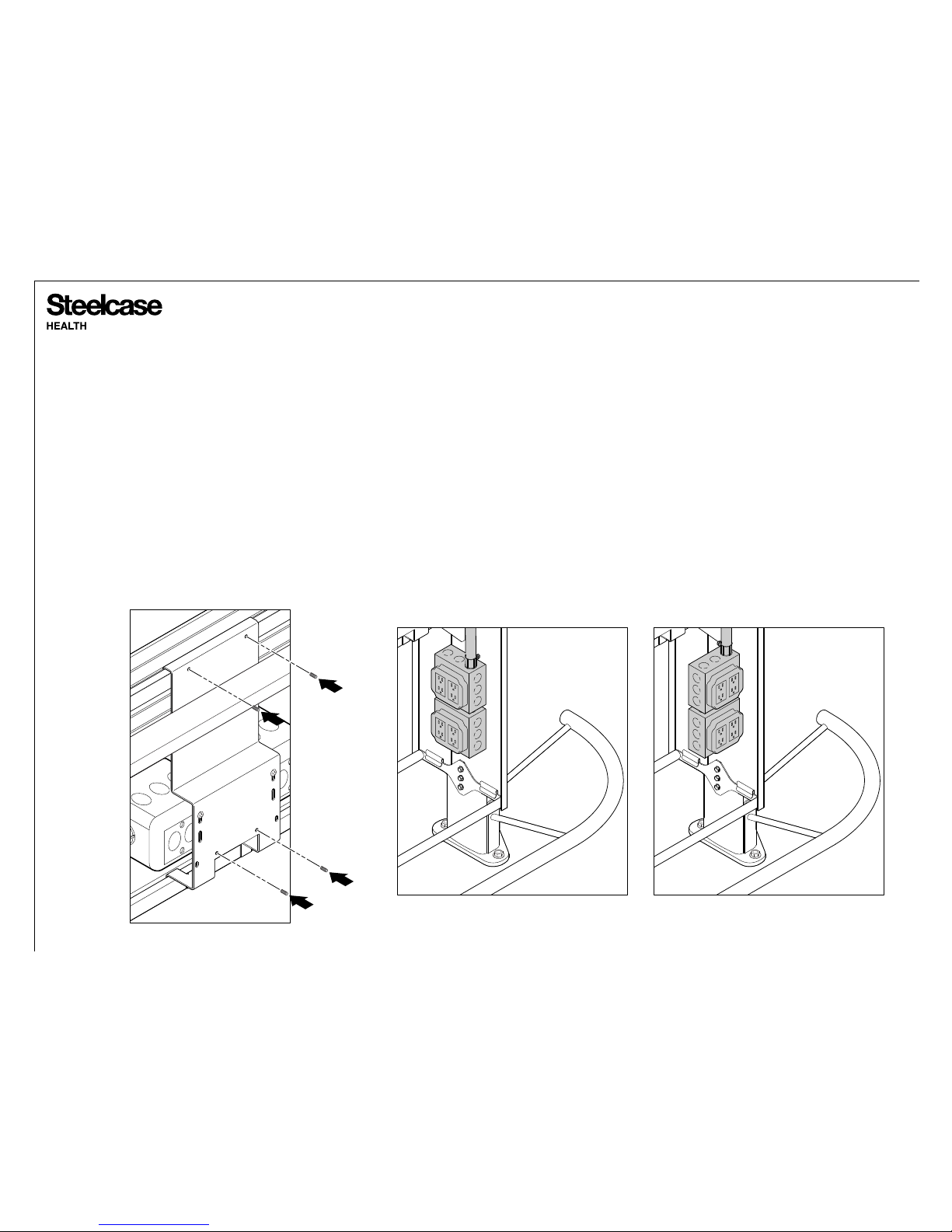
• Finish by securing the set screws for the multi-purpose
brackets to keep secure to the faceplate support bracket.
• 4 x 4 j-boxes can be attached to the inside of each leg
for additional receptacle locations. These j-boxes can be
mounted flat to the leg or mounted perpendicular for extra
receptacles. The flex conduit from the desk height
assembly can be mounted to these j-boxes or directly to
the building power sources.
• The type and amount of circuits is determined by the
electrical engineer or customer and is only limited to the
size and type of electrical hardwire devices used by the
electrician and dictated by the local codes.
J-BOXES MOUNTED
FLAT TO THE LEG
J-BOXES MOUNTED
PERPENDICULAR TO THE LEG
Page 10
Page 10 of 15
939549943 Rev G
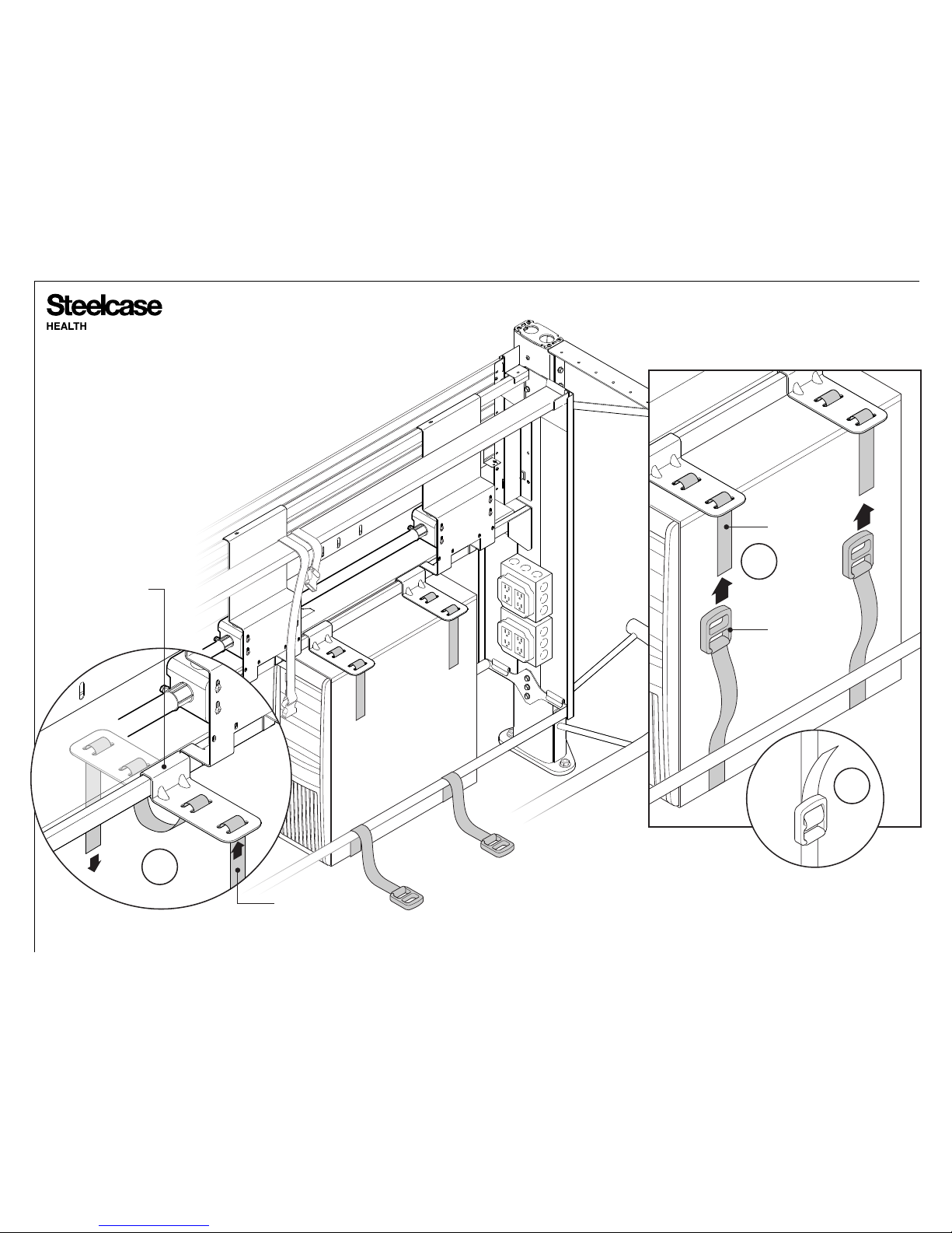
13. Thread straps through
slots of each CPU mount
plate, as shown.
14. Route straps upward, as
shown, (14a) and secure straps
into clips (14b).
13
14a
14b
CPU MOUNT
PLATE
60" LONG STRAP
CLIP
STRAP
Page 11
Page 11 of 15
939549943 Rev G
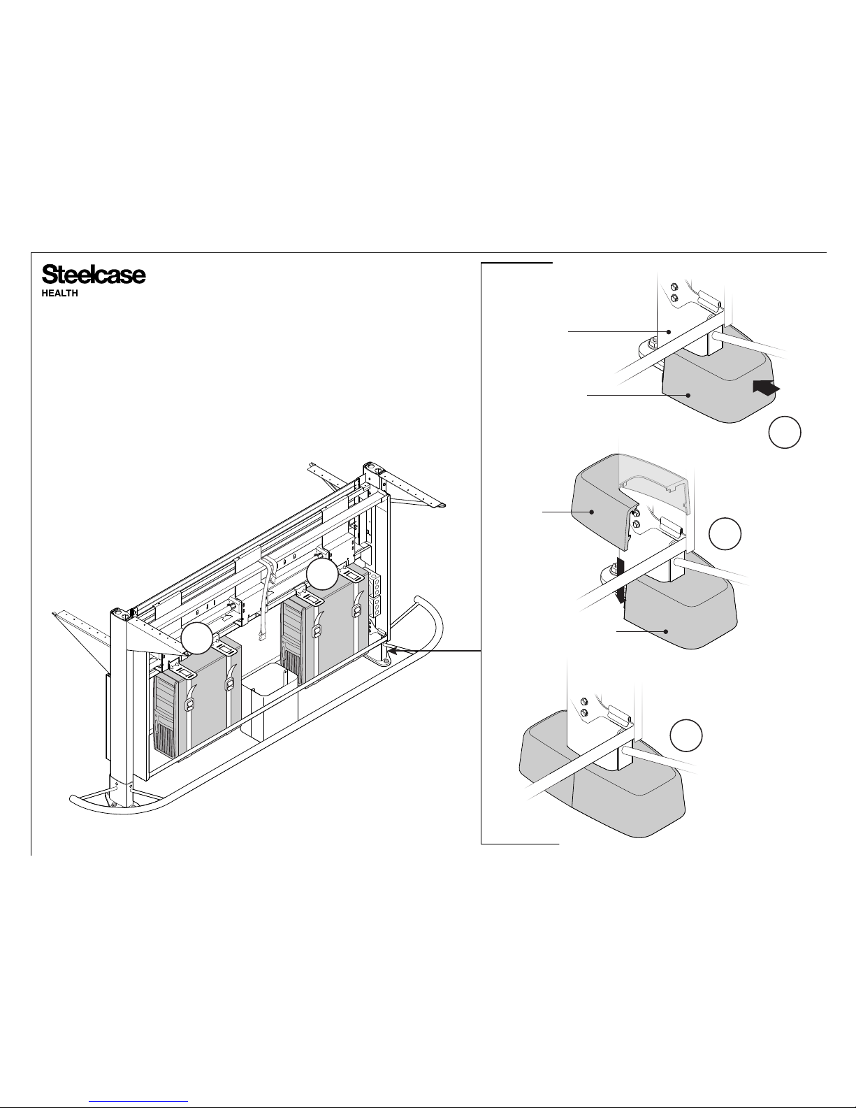
15. An additional CPU may be
installed next, as shown.
16. For each foot, a foot cover
needs to be installed. Install the
RH foot cover so it encompasses
the leg column as shown (16a).
Install the LH foot cover next to
the RH foot cover by sliding
downward and engaging the RH
foot cover (16b) until it is fully
secured into place (16c).
16a
16b
16c
15
15
LEG
COLUMN
RH FOOT
COVER
LH FOOT
COVER
RH FOOT
COVER
Page 12
Page 12 of 15
939549943 Rev G
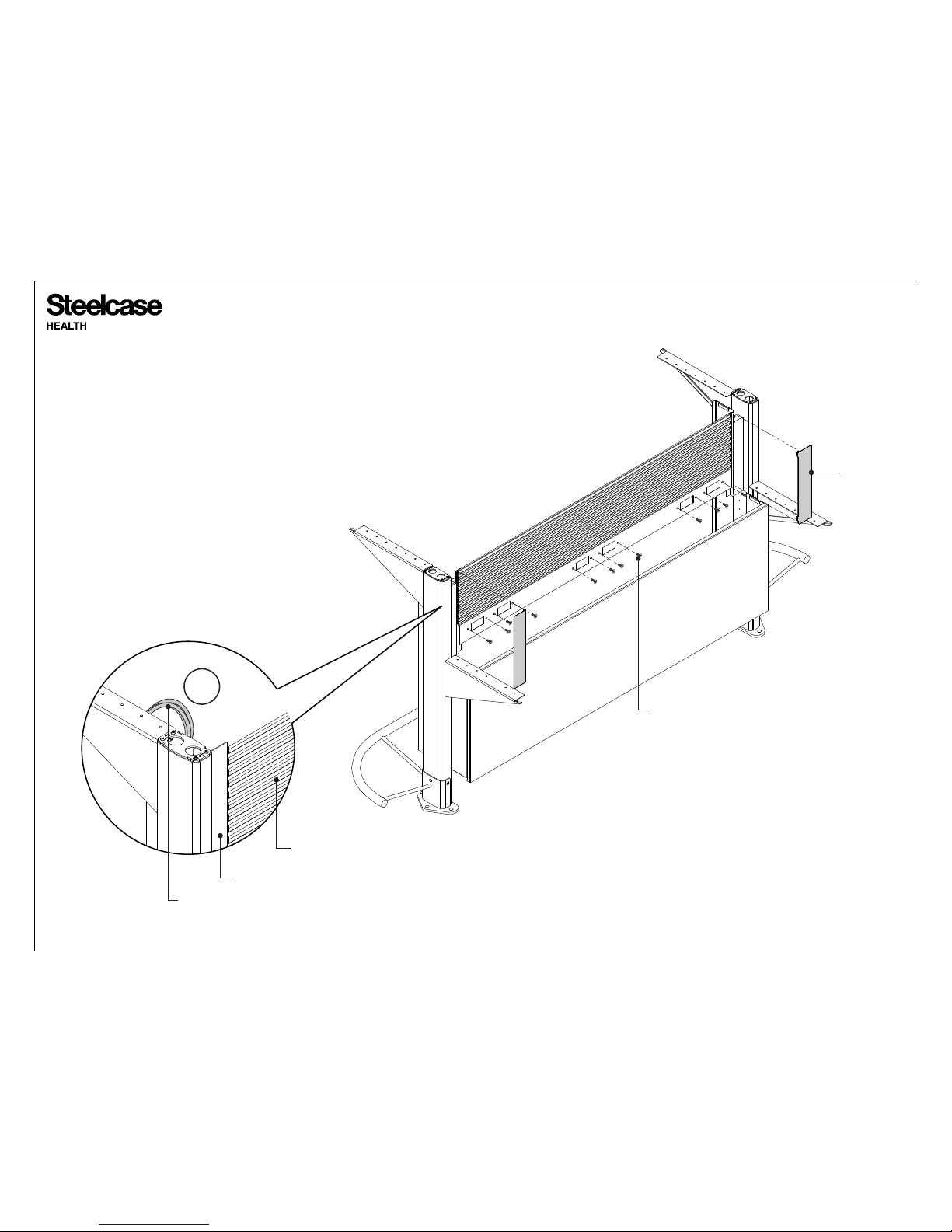
17. Remove side panel cover so plugs and cords can be
routed through. Once cords have been routed, slide cords
into 1/4" gap that exists between notch in worksurface
and leg. Replace side panel cover when completed.
The monitor arms (if applicable) and the worksurfaces
may be installed at this point. There are separate
assembly directions for these applications.
17
SIDE PANEL COVER
SUPPLIED STAINLESS
STEEL SCREW
SLATWALL
SIDE PANEL COVER
CORDS
Page 13
Page 13 of 15
939549943 Rev G
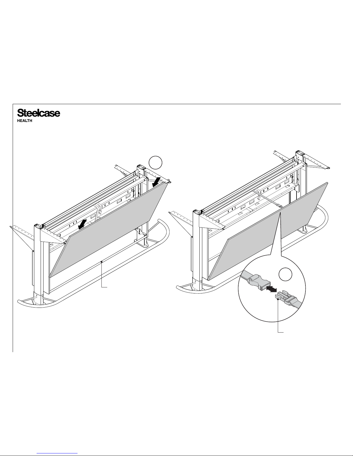
18. Lower the bottom tile brackets onto
the lower support bar.
19. Connect longest strap.
18
19
LOWER SUPPORT BAR
COUPLER
Page 14
Page 14 of 15
939549943 Rev G
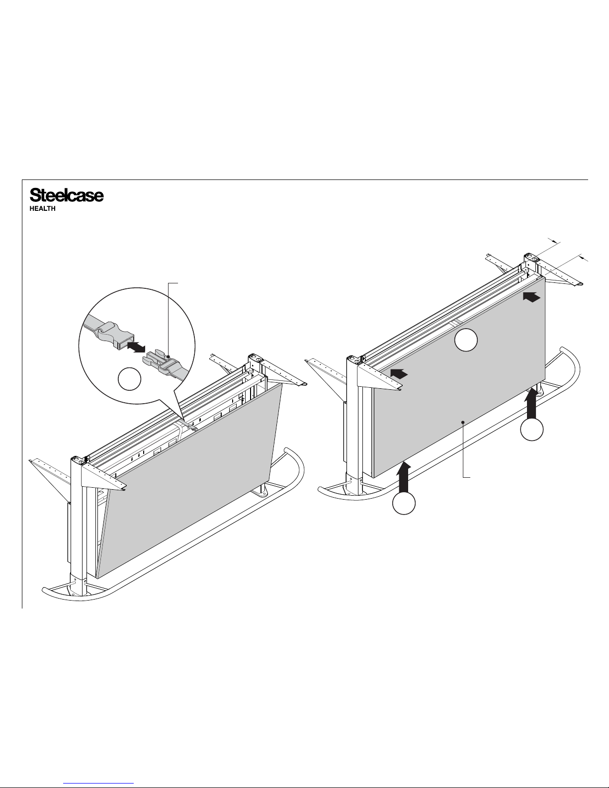
20. Connect short strap. 21a. Snap tile into place by pushing it
very firmly at the upper corners
of the tiles until both retention
clips fully engage.
20
21a
8-9/16"
COUPLER
TILE
21b. Slightly raise the tile if necessary to
line up the retention clips.
21b
21b
Page 15
Page 15 of 15
939549943 Rev G
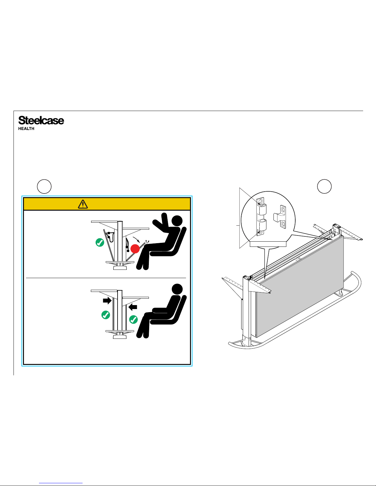
22a. Slightly pull the tile outward to make sure retention clips are
fully engaged. If the tile is still loose, repeat steps 21a and 21b.
See caution label 22a.
22b. If needed, screws on retention clips behind the upper
corners of the tile could be turned to adjust the tension.
22a
SCREWS
22b
Follow all manufacturers’ instructions for installation and use.
Obtain assembly directions from your Steelcase dealer or call 1-888-783-3522.
939500525
CAUTION
ALWAYS CONNECT BOTH
SAFETY STRAP BUCKLES
WHEN CLOSING TILE to
prevent it from falling and
causing injury.
Also, push very firmly to fully
engage both retention clips
at upper corners of the tile
and verify the connection.
If tile is still loose, it is not
fully engaged.
X
RETENSION CLIPS
 Loading...