

Page 1
®
If you have a problem, question, or request, call
your local dealer, or Steelcase Line 1 at
888.STEELCASE (888.783.3522)
for immediate action by people who want to help you.
(Outside the U.S.A., Canada, Mexico, Puerto Rico,
and the U.S. Virgin Islands, call: 1.616.247.2500)
Or visit our website: www.steelcase.com
©
2016 Steelcase Inc.
Grand Rapids, MI 49501
U.S.A.
Printed in U.S.A.
Answer® Recessed Frameless Glass
Open this side
Abra de este lado
Ouvrir de ce côté
READ DIRECTIONS AND
MANUAL FIRST
LEA PRIMERO LAS
INSTRUCCIONES Y EL MANUAL
LISEZ D’ABORD LES
DIRECTIVES ET LE GUIDE
>5º
Safety Instructions Instrucciones de Seguridad Consignes de Sécurité
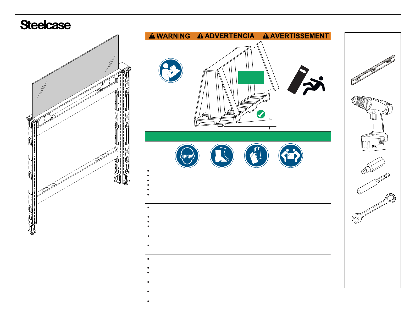
Before opening, ensure crate is stable and tilted at least 5 degrees to prevent glass from falling out.
To open, cut any bands first and pry off boards on front of crate.
Before removing glass, check crate and remove protruding nails or screws that could scratch glass.
Wear appropriate personal protective equipment (safety glasses, gloves, safety shoes and skin protection).
Tempered Glass is very heavy and can shatter while handling. Use two or more people to handle glass.
Handle carefully. A scratched surface, damaged surface, or edge impact can cause the glass to shatter
suddenly into sharp pieces.
Antes de abrir, asegúrese de que la caja esté estable e inclinada al menos por 5 grados para evitar que el
vidrio se salga de la caja.
Para abrir, corte primero las bandas de embalaje y luego separe las tablas del frente de la caja.
Antes de retirar el vidrio, chequee la caja y quite los clavos o tornillos salientes que puedan rayar el vidrio.
Use el equipo apropiado de protección personal (gafas de seguridad, guantes, zapatos de seguridad y
protección para la piel).
El vidrio templado es muy pesado y se puede romper durante su manipulación. Use dos o más personas
para manipular el vidrio.
Manéjelo con cuidado. Una superficie rayada o dañada, o el impacto sobre el borde pueden causar que el
vidrio se rompa de repente en trozos afilados.
Avant d'ouvrir, assurez-vous que la caisse à claire-voie est stable et inclinée d'au moins 5 degrés pour éviter
que la vitre bascule hors de la caisse.
Pour ouvrir, coupez d'abord les bandes d'emballage, puis écartez les bords sur le devant de la caisse.
Avant de retirer la vitre, vérifiez la caisse et enlevez les clous ou les vis qui pourraient dépasser et qui
pourraient égratigner la vitre.
Portez de l'équipement de protection individuelle approprié (lunettes de sécurité, gants, chaussures de
sécurité et vêtements de protection).
Le verre trempé est très lourd et peut se briser en éclats lorsqu'on le manipule. Au moins deux personnes
sont nécessaires pour manipuler la vitre.
Manipulez avec soin. Une surface égratignée ou endommagée ou encore un choc sur le rebord peut faire en
sorte que le verre se brise soudainement en éclats tranchants.
RISK OF SERIOUS INJURY
RIESGO DE LESIONES GRAVES
RISQUE DE GRAVES BLESSURES!
Page 1 of 12
939501795 Rev G
Page 2
®
1.
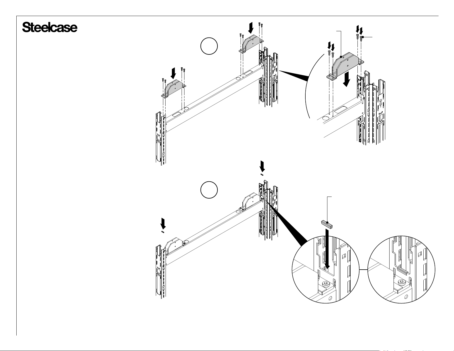
Mount a support bracket at each end of the
horizontal beam using four (4) 1/4-20 x 3/4" flat
head thread forming hex cap screws (blue color
screws) installed into the holes on the beam.
• If the holes are not on the beam, go to page 6.
• If the glass is longer than 72", go to page 6.
2. Place a grommet on each post at the location
shown. The bottom edge of the glass will rest on
the grommets when assembled.
SUPPORT BRACKET
1/4-20 x 3/4"
1
FLAT HEAD THREAD
FORMING HEX CAP SCREW
(BLUE SCREW SUPPLIED)
2
GROMMET
Page 2 of 12
939501795 Rev G
Page 3
®
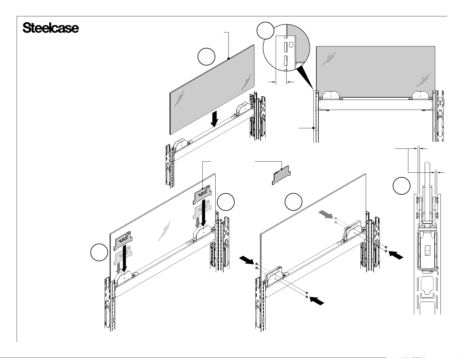
3. Place glass inside each support bracket and rest
the glass on the grommets (3a). Center the glass
between the posts to which it’s supported (3b).
4. Place a pressure plate inside the space between
the support bracket and the glass in four (4)
locations. Locate each pressure plate as shown.
Plates manufactured after December, 2015 will be
stamped “THIS SIDE AWAY FROM GLASS”.
GLASS
3a
3b
EQUAL ON
BOTH ENDS
POST
TIP: If adjacent pieces of glass are not sufficiently
vertically aligned, shim below the lower of the two
pieces prior to tightening pressure plate bolts.
5. Install all four (4) bolts until they contact the
pressure plate on the outside of each support
bracket (5a). The amount of threads shown on the
bolts should be the same (5b). The glass should be
vertical and firmly resist deflection with a light 2 to
3 pound lateral load on the face of the glass.
4
PRESSURE PLATE
(manufactured before
December, 2015)
4
PRESSURE PLATE
5a
BEGIN BY SETTING ALL
FOUR (4) SCREWS EQUAL
UNTIL THERE IS CONTACT
WITH THE PRESSURE PLATE
5b
Page 3 of 12
939501795 Rev G
Page 4
®
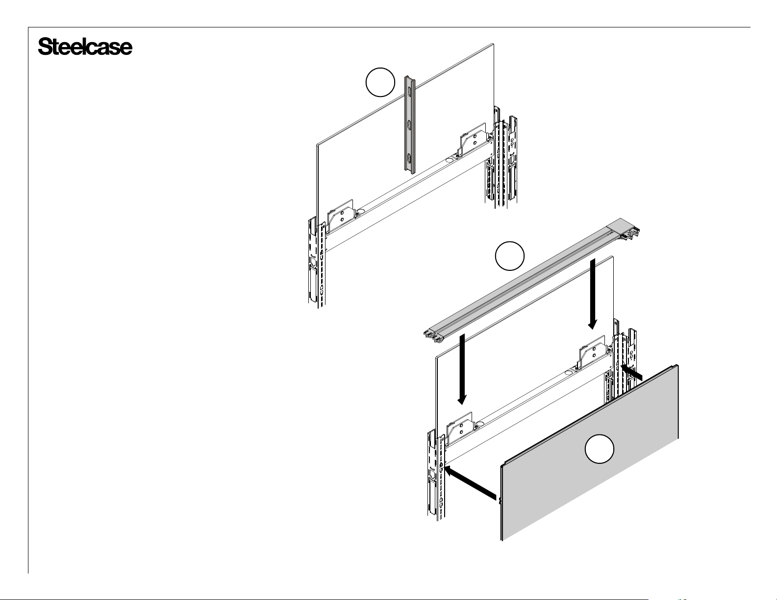
6. Verify that the glass is vertical and laterally
centered per step 3b.
7. Tighten the top bolts on each support bracket
1/2 turn.
8. At this point the glass should be vertical and
aligned top and bottom to adjacent glass.
9. Torque all screws 1 to 2 turns, confirming that
the glass remains vertical.
10. Install the skins to the frame.
11. Install the top trim with plastic junction caps &
trim aligners (See pages 7 through 11).
6
11
10
Page 4 of 12
939501795 Rev G
Page 5
®
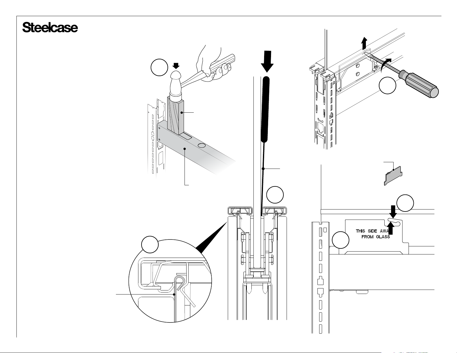
Adjusting Top Trim To Level
1. The top surface of the top trims should be
level within 1/64". If not, verify that the
horizontal beam is fully installed.
2. The top trim can be raised (2a) or lowered
(2b) by bending the loop / leg on the pressure
plate up or down to level the top trim.
3. Verify that the top trim aligns with the
plastic end piece that is inserted into it. If not,
go to next step.
4. The light seal on skin locates the top trim.
If needed, the top cap can be removed to
allow bending in or out to align.
1
2a
2" x 4" x 8" LONG
WOOD BLOCK
PRESSURE PLATE
PUTTY
KNIFE
HORIZONTAL BEAM
(manufactured before
December, 2015)
2b
2b
LIGHT
SEAL
4
2a
Page 5 of 12
939501795 Rev G
Page 6
®
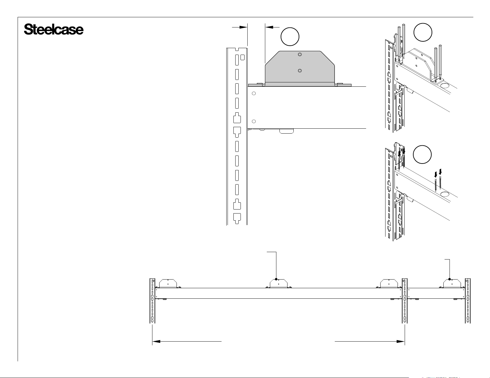
Mounting Support Bracket to Older Horizontal Beam
NOTE: The holes for mounting the support bracket may not be
pre-drilled on the older horizontal beams. When this occurs, use the
support bracket as a template to locate the hole locations and follow
steps below to drill mounting holes.
1. Place the support bracket onto the top horizontal beam 1-1/4"
from the side of the vertical upright (1a). Using the support bracket
as a template, mark the hole locations as shown (1b).
NOTE: The 1-1/4" dimension can vary 1" without affecting the
integrity of the mount.
2. Use a 1/16" diameter drill bit to center the hole locations, then
use a 3/16" diameter drill bit to complete the hole mounting
locations.
1-1/4"
1a
1b
2
Mounting Glass 72 Inches and Longer
If the glass is 72 inches or longer, a third
support bracket is required. Two (2)
support brackets need to be mounted on
the longest horizontal beam and the third
support bracket at the end of the adjoining
horizontal beam. At least one grommet
should be installed to the inboard junction
post (see step 2 on page 2).
* When using a 72" glass kit on a 72"
horizontal beam, place the third support
bracket in the center of the beam. The
holes are not pre-drilled. Add holes as
described in step 1b and 2 above.
* THIRD SUPPORT BRACKET
WHEN USING A 72" GLASS KIT
ON A 72" HORIZONTAL BEAM
MAXIMUM HORIZONTAL BEAM LENGTH = 72"
THIRD SUPPORT BRACKET
Page 6 of 12
939501795 Rev G
Page 7
®
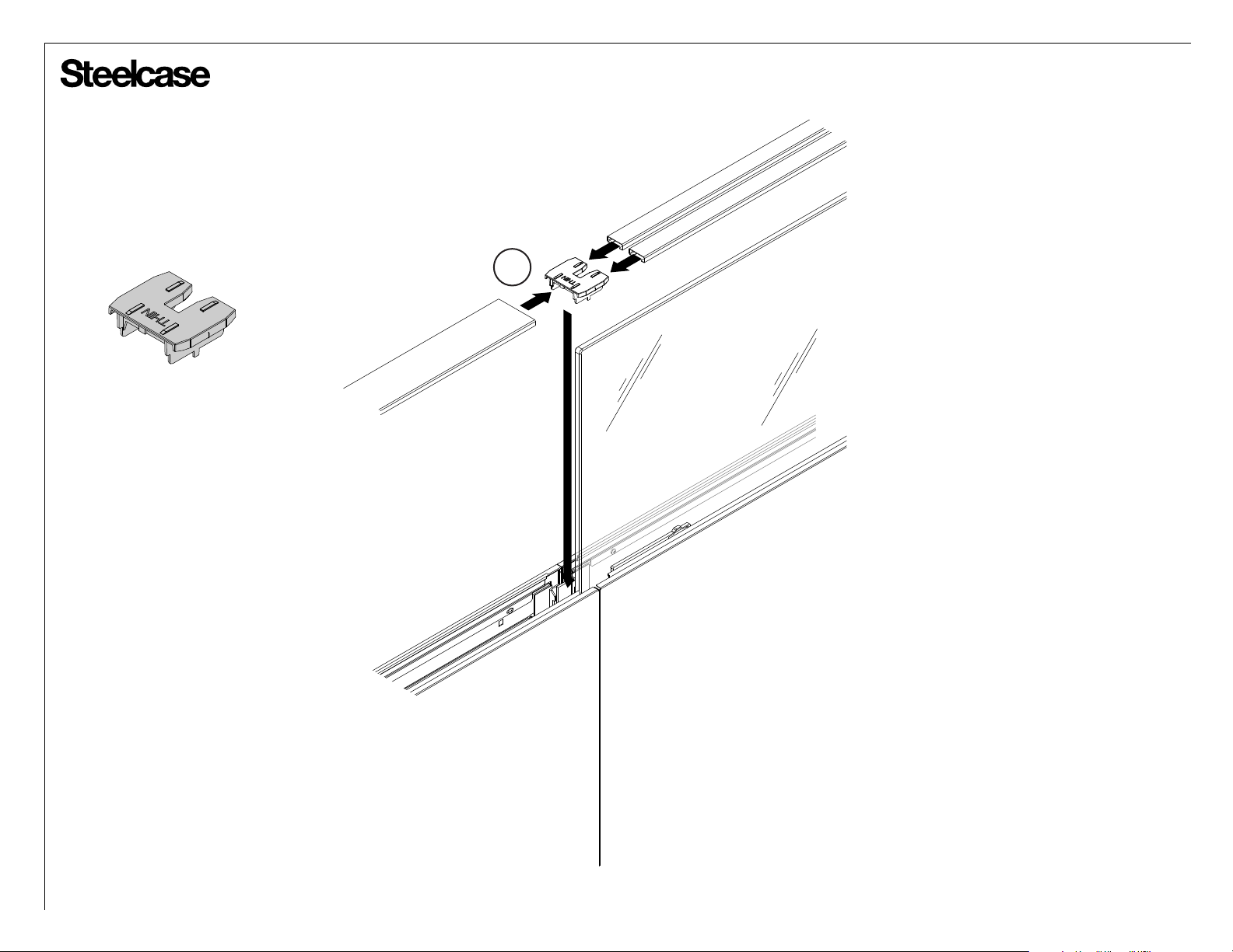
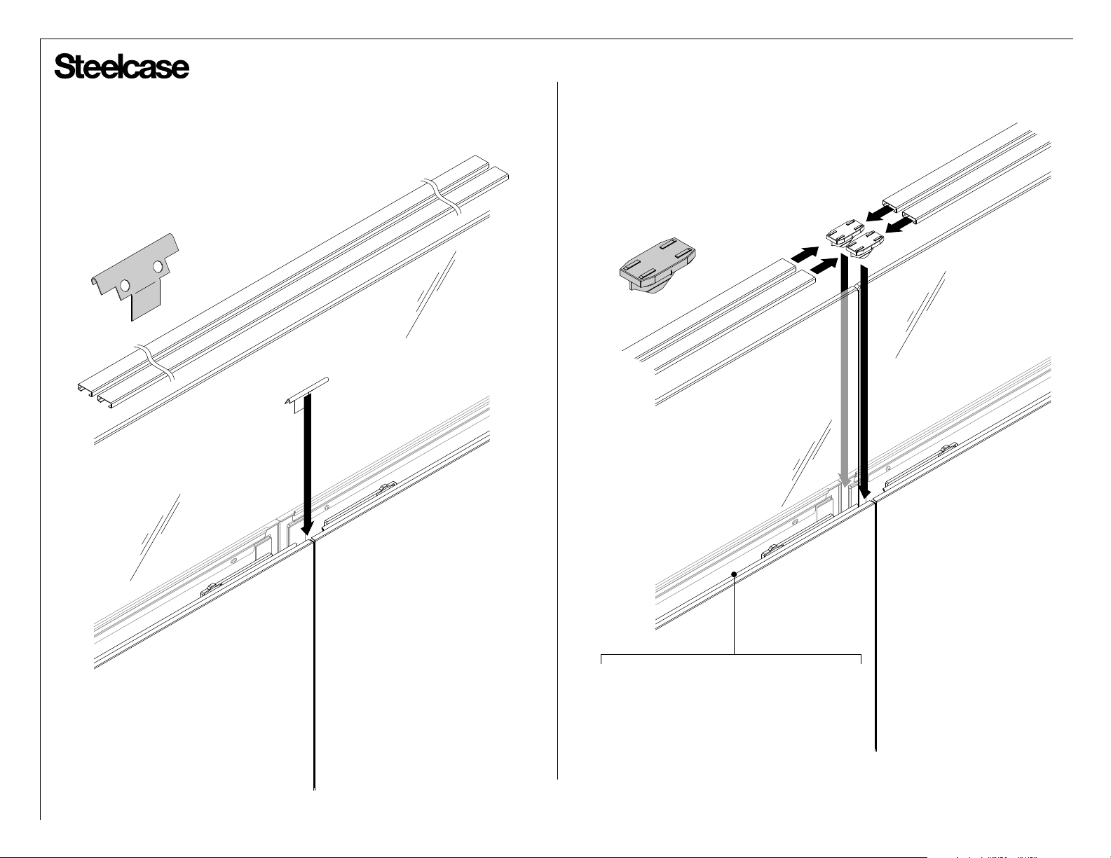
Connector Application
IN-LINE
1
Page 7 of 12
939501795 Rev G
Page 8
®
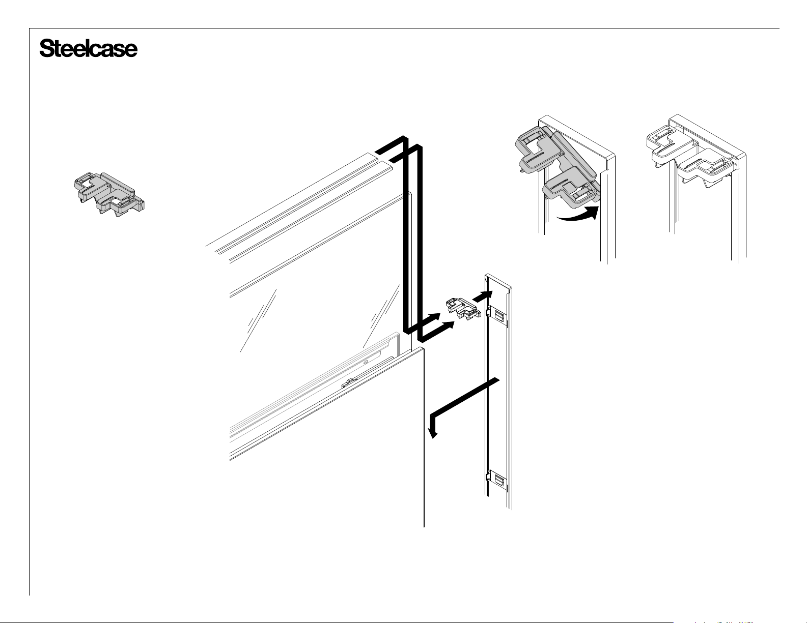
Connector Application
END-OF-RUN
Page 8 of 12
939501795 Rev G
Page 9
®
Connector Application
SPANNING GLASS IN-LINE
GLASS-TO-GLASS IN-LINE
TIP: To ensure a tighter fit of top caps to
glass, it is helpful to bend the skin light
seals toward the glass (at the location
where the top cap spring clips reside).
Page 9 of 12
939501795 Rev G
Page 10
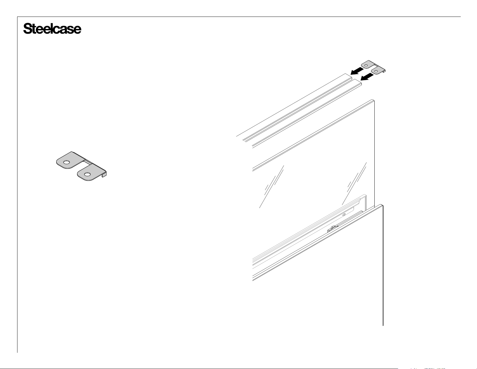
®
Connector Application
WALL START
OFF-MODULE FIN
CHANGE OF HEIGHT (if no plastic aligner is present)
UTILITY POLE
TS7TFGRC Recessed Frameless Glass Top Cap
Connector is ordered separately from the Answer
Thin Recessed Frameless Glass Kit. It is applied
whenever a plastic aligner cannot be applied to the
end of Recessed Frameless Glass Top Caps.
Page 10 of 12
939501795 Rev G
Page 11
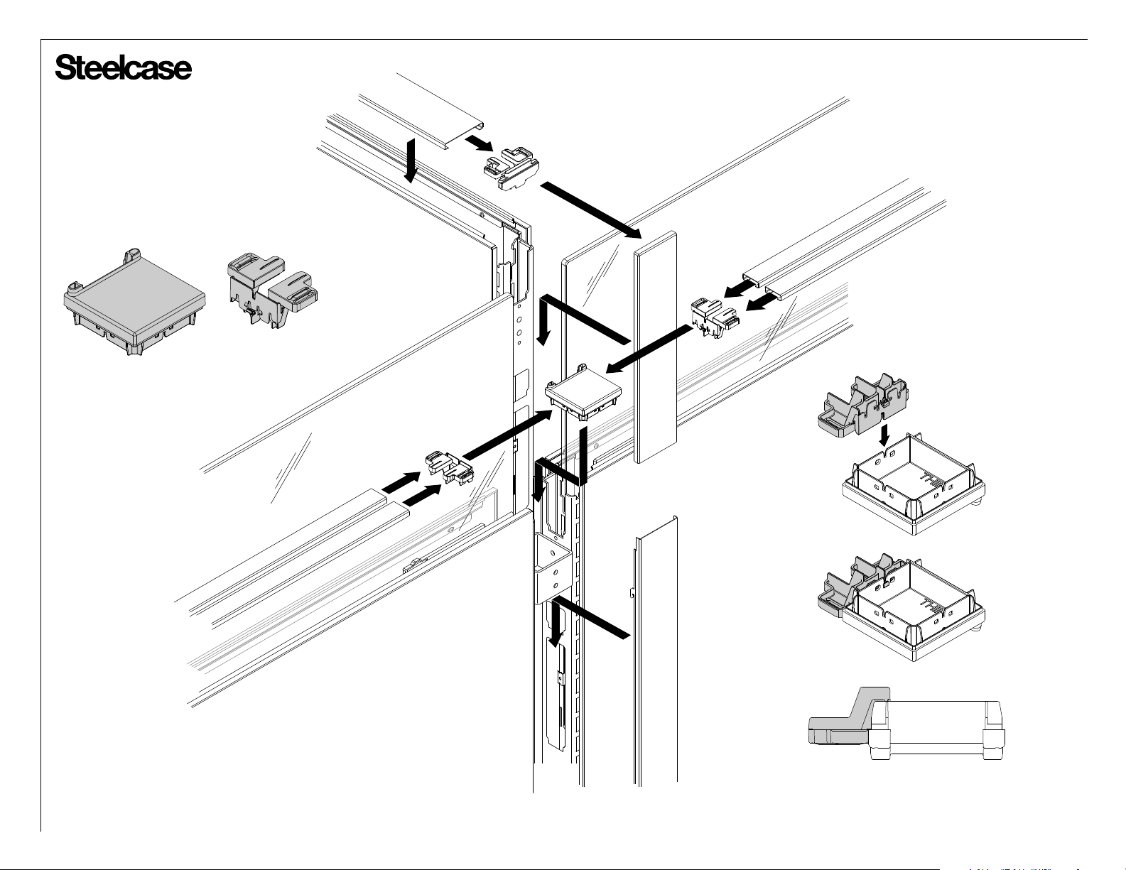
®
Connector Application
‘T’ CHANGE-OF-HEIGHT (COH)
X2
X2
Page 11 of 12
939501795 Rev G
Page 12
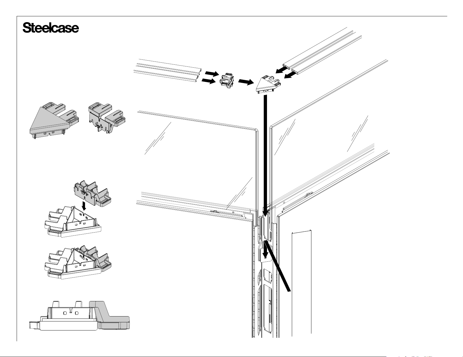
®
Connector Application
120 DEGREE CORNER
Page 12 of 12
939501795 Rev G
 Loading...