

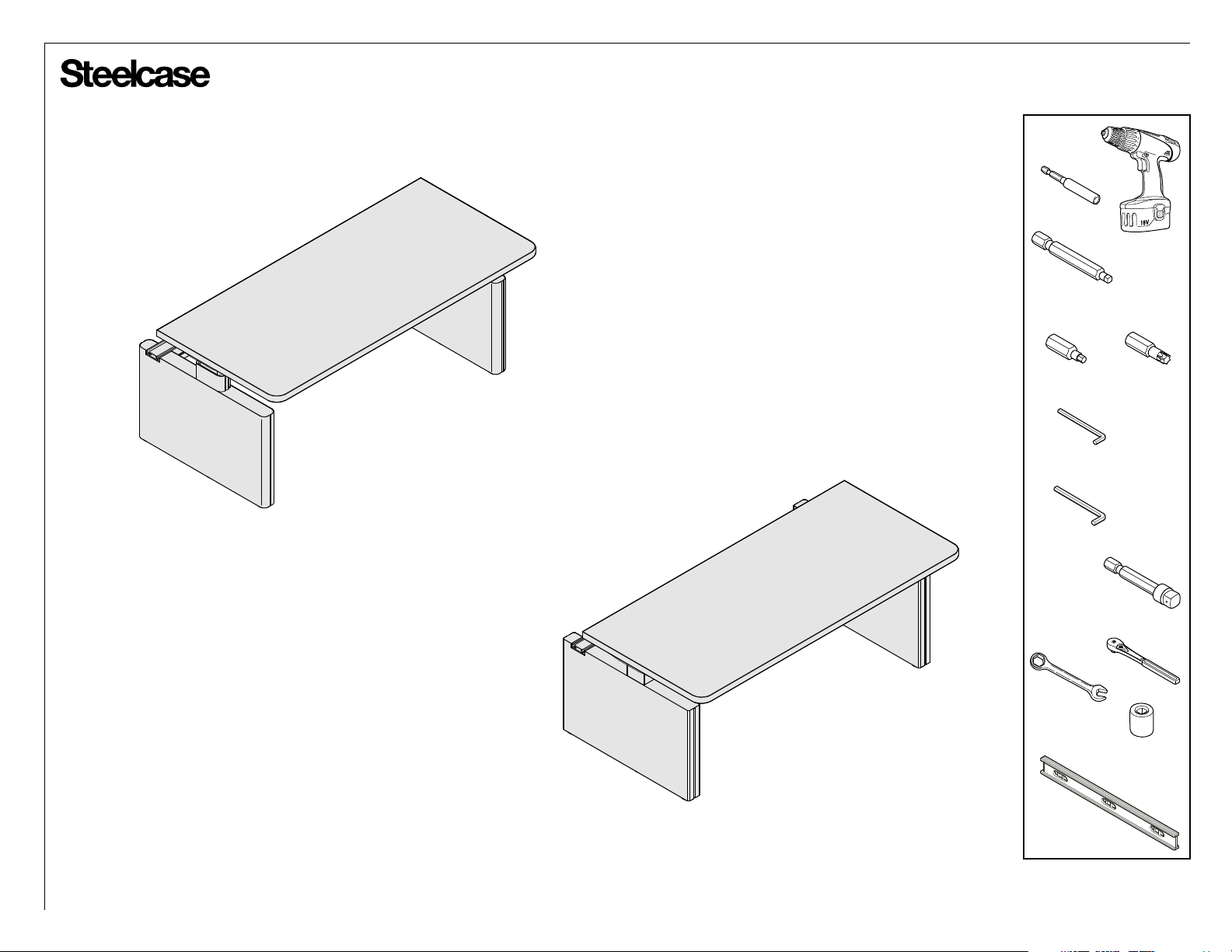
Steelcase 8, 5 Series Series Manual
®
Single Sided Height Adjustable Benching
Bit Holder
Power Drill
Long #2 Square
Drive Bit
SERIES 5
If you have a problem, question, or request, call
your local dealer, or Steelcase Line 1 at
888.STEELCASE (888.783.3522)
for immediate action by people who want to help you.
(Outside the U.S.A., Canada, Mexico, Puerto Rico,
and the U.S. Virgin Islands, call: 1.616.247.2500)
Or visit our website: www.steelcase.com
©
2015 Steelcase Inc.
Grand Rapids, MI 49501
U.S.A.
Printed in U.S.A.
SERIES 8
5mm
Hex Drive Bit
Hex Key - 2.5mm
(Provided)
Hex Key - 3mm
10mm
Wrench
T-30
Torx Drive Bit
Socket Adaptor
(or)
Ratchet
8mm & 10mm
Sockets
Level
Page 1 of 38
939564909 Rev B

®
IMPORTANT SAFETY INSTRUCTIONS
When using an electrical furnishing, basic precautions should always be followed, including the following:
Read all instructions before using (this furnishing).
DANGER - To reduce the risk of electric shock:
1. Always unplug this furnishing from the electrical outlet before cleaning.
WARNING - To reduce the risk of burns, fire, electric shock, or injury to persons:
1. Always unplug this furnishing from the electrical outlet before cleaning.
2. Close supervision is necessary when this furnishing is used by, or near children, invalids, or disabled persons.
3. Use this table only for its intended use as described in these instructions. Do not use attachments not
recommended by the manufacturer.
4. Never operate this table if it has a damaged cord or plug, if it is not working properly, if it has been dropped or
damaged, or dropped into water.
5. Keep the cord away from heated surfaces.
6. Never drop or insert any object into any opening.
7. Do not use outdoors.
8. Do not operate where aerosol (spray) products are being used or where oxygen is being administered.
9. For loading always put heavier items at the bottom and not near the top in order to help prevent the possibility
of the furnishing tipping over.
SAVE THESE INSTRUCTIONS
The power socket/outlet shall be installed near the equipment and shall be easily accessible.
OPERATING INSTRUCTIONS - Please refer to the attached Installation Instructions and the provided User Guide.
USER-MAINTENANCE INSTRUCTIONS - The receptacle power block is equipped with a circuit breaker that will shut
off power in an overload condition. Press to reset the circuit breaker to restore power.
POLARIZED PLUG INSTRUCTIONS (Series 8 only) - To reduce the risk of electrical shock, this furnishing has a
polarized plug (one blade is wider than the other) like the plug illustrated in Figure 1. This plug will fit in a polarized
outlet only one way. If the plug does not fit fully in the outlet, reverse the plug. If it still does not fit, contact a qualified
electricial to install the proper outlet. Do not change the plug in any way.
GROUNDING INSTRUCTIONS (Series 5 only) - This product must be grounded. Connect this appliance to a properly
grounded outlet only. If it should malfunction or breakdown, grounding provides a path of least resistance for electric
current to reduce the risk of electric shock. This product is equipped with a cord having an equipment-grounding
conductor and a grounding plug. The plug must be plugged into an appropriate outlet that is properly installed and
grounded in accordance with all local codes and ordinances.
DANGER - Improper connection of the equipment-grounding conductor can result in a risk of electric shock. Check with
a qualified electrician or serviceman if you are in doubt as to whether the product is properly grounded. Do not modify
the plug provided with the product - if it will not fit the outlet, have a proper outlet installed by a qualified electrician.
This product is for use on a nominal 120-V circuit and has a grounding plug that looks like the plug illustrated in
sketch A in Figure 2. Make sure that the product is connected to an outlet having the same configuration as the plug.
No adapter should be used with this product.
GROUNDING
(A)
GROUNDED
OUTLET BOX
(B)
SERIES 8 ONLY
Figure 1
Polarized Plug
SERIES 5 ONLY
GROUNDED
OUTLET
PIN
GROUNDED
OUTLET BOX
ADAPTER
METAL
SCREW
TAB FOR
GROUNDING
SCREW
Figure 2
Grounding methods
Page 2 of 38
939564909 Rev B

®
TABLE OF CONTENTS:
Lets Get Started!............................................................................................
Attaching Mounting Plate to Lifting Columns (Series 5 & 8)......................
Mounting Lifting Columns to Worksurfaces (Series 5 & 8)........................
Series 5 Table Assembly
- Determine Switch Position on your Table...............................................
- Identify the Master & Slave Motors.........................................................
- Installing Driveshafts..............................................................................
- Installing Switch & Power Supply............................................................
- Attaching Driveshaft Covers & Wire Managers......................................
- Connect and Route All Cables................................................................
- Connecting the Table Assemblies & Installing the Center Beam............
- Finishing the Table Assembly..................................................................
Series 8 Table Assembly
- Attaching Control Box & Wire Managers................................................
- Connecting & Routing Cables................................................................
- Attaching the Controller..........................................................................
- Finishing the Lifting Column Installation.................................................
- Connecting the Table Assemblies & Installing the Center Beam............
- Finishing the Table Assembly..................................................................
Installing the Inline Connector........................................................................
Assembling & Attaching the Modular Power Blocks......................................
Assembling & Attaching the Hardwire Power Blocks.....................................
PAGE(S):
4
5
6 - 7
8
9
10 - 13
14
15
16
17
19
20
21
22
23
24
26 - 27
28
29 - 30
31
STOP - Electrical Inspection Required before moving on!
Attaching the Power Trays & Data Tray.........................................................
Attaching Interior Covers...............................................................................
32 - 35
36 - 37
Page 3 of 38
939564909 Rev B
®
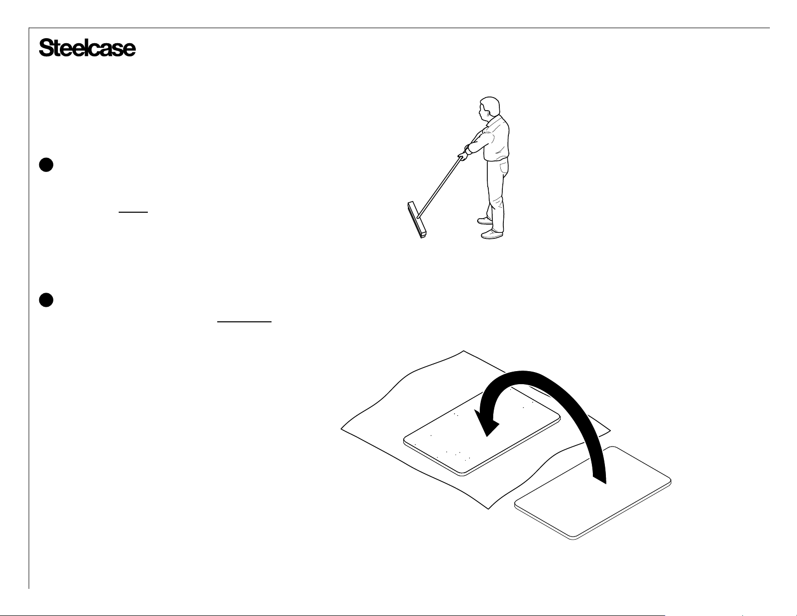
Prepare a large open space to assemble the table.
1
• Sweep the floor! Screws and small parts can damage
the worksurface.
• Put down a CLEAN shipping blanket to protect the worksurfaces.
Unpack the worksurfaces and place on the shipping blanket upsid e-down.
2
• REMEMBER - You're looking at the UNDERSIDE of the worksurfaces.
Are you sure which side is left or right and front or rear?
Page 4 of 38
939564909 Rev B
®
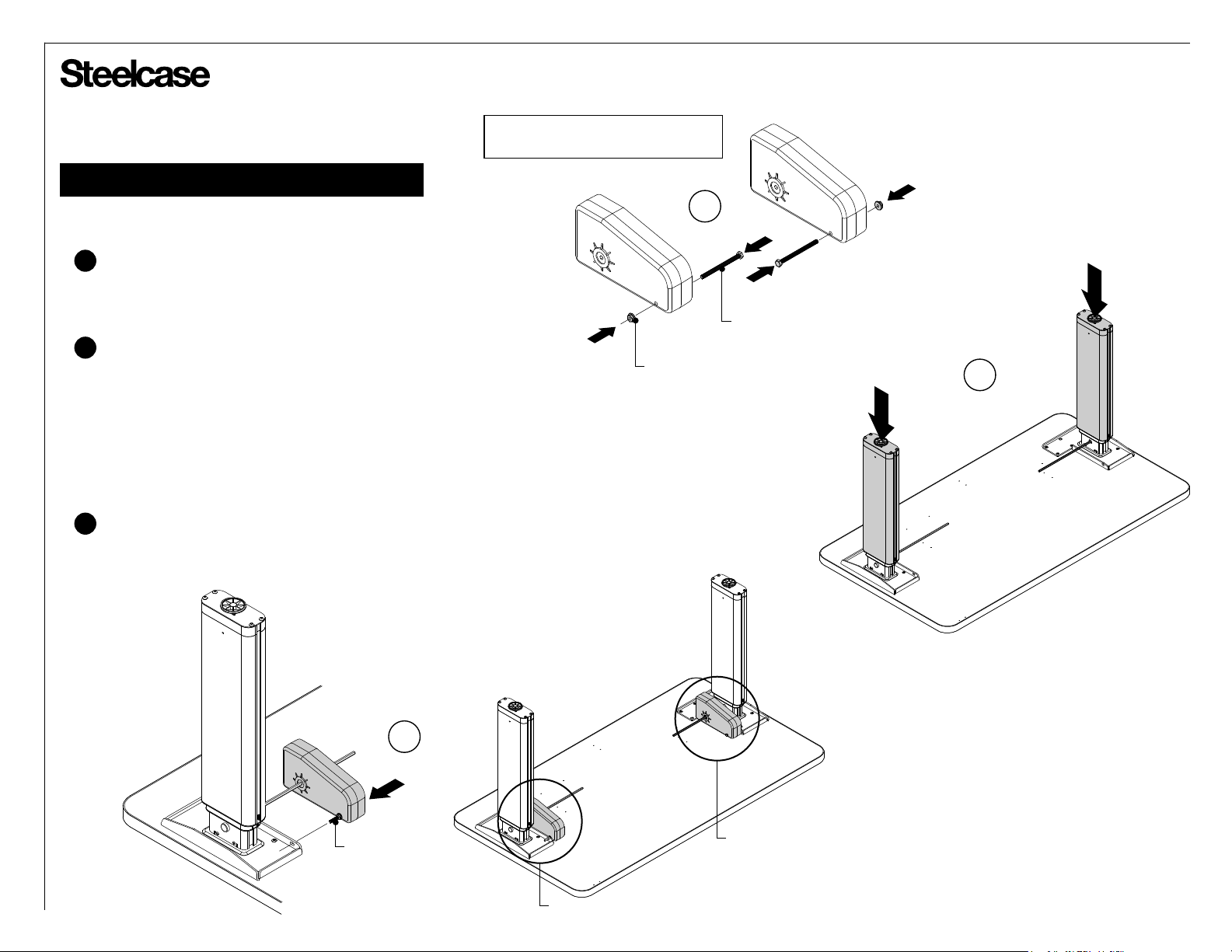
Attaching Mounting Plate to Lifting Columns
3
Series 8 lifting columns are handed.
Secure the plastic strain relief block in
the notch provided in each lift column
before assembling mounting plate.
Locate and install each mounting plate
using 5mm (for Series 5) or 6mm (for
Series 8) hex head fasteners provided.
Do not over-tighten.
TOWARD CENTER
OF WORKSURFACE
8mm HEX HEAD M5 x 25 BOLTS
STUDS ON BACK OF
(TIGHTEN GENTLY WITH
3mm HEX KEY IF LOOSE)
MOUNTING PLATE
LIFTING COLUMN
TOWARD BACK
OF WORKSURFACE
Series 5
Series 8
10mm HEX HEAD M6 x 25 BOLTS
MOUNTING PLATE
STUDS ON BACK OF
LIFTING COLUMN
(TIGHTEN GENTLY WITH
3mm HEX KEY IF LOOSE)
PLASTIC STRAIN RELIEF
WIRING
HARNESS,
TOWARD CENTER
OF WORKSURFACE
NOTCH
Page 5 of 38
939564909 Rev B
®
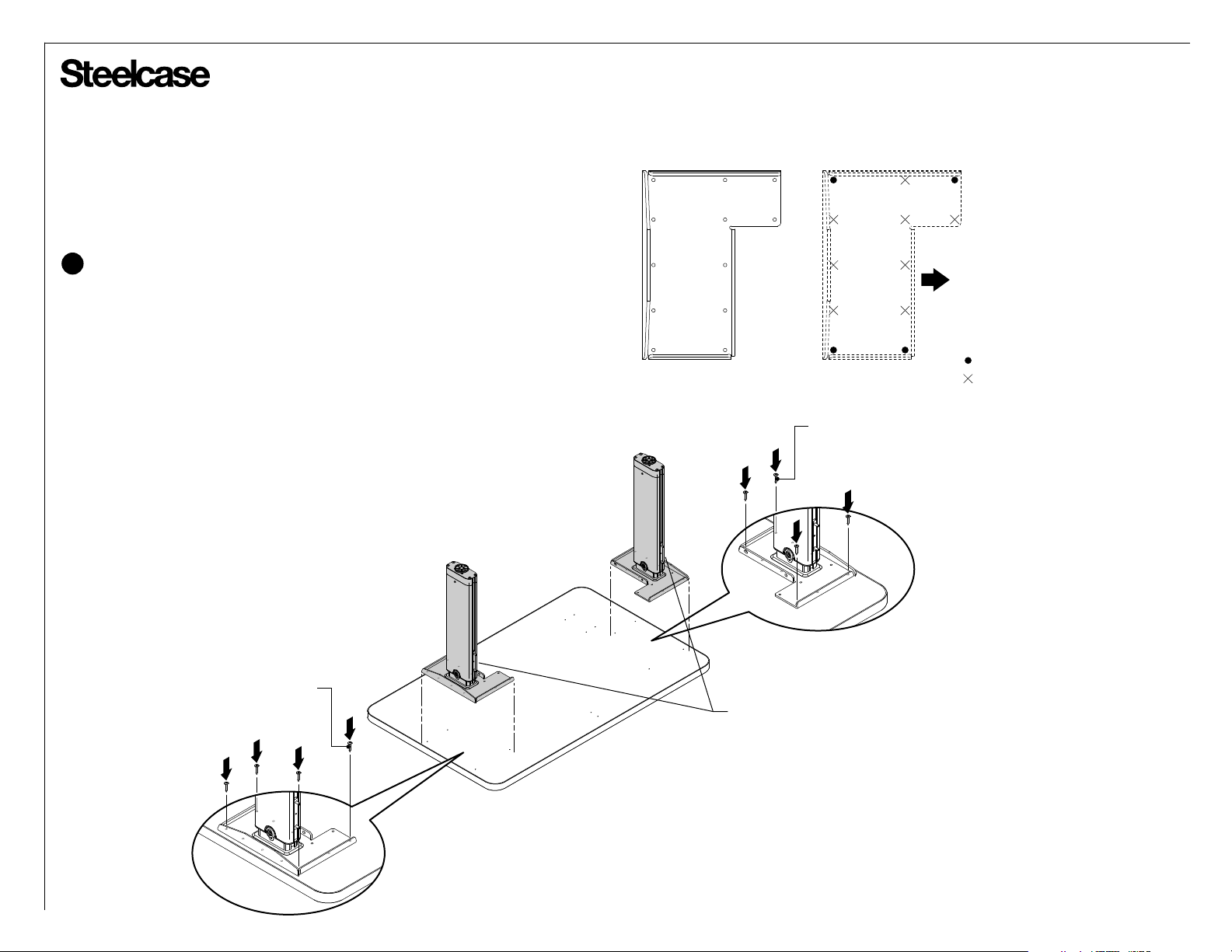
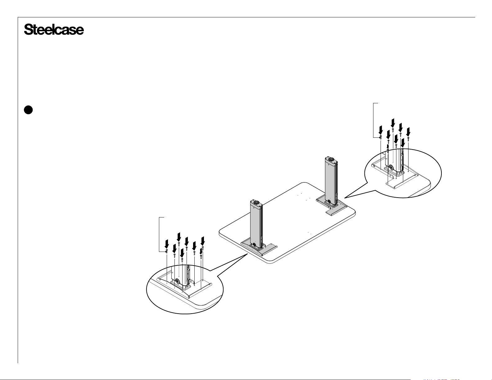
Mounting Lifting Columns to Worksurfaces
4
With the top still upside down on the floor,
turn each leg assembly over and align the
mounting plates to the pre-drilled holes in
the top.
Mounting Plate
Worksurface
Pilot Holes
TOWARD CENTER
OF WORKSURFACE
Install one fastener in each of the
pre-drilled pilot holes.
#2 SQUARE DRIVE
WORKSURFACE
SCREW
= PILOT HOLE
= NO PILOT HOLE PROVIDED
#2 SQUARE DRIVE
WORKSURFACE
SCREW
STUDS FACING BACK
OF WORKSURFACE
Page 6 of 38
939564909 Rev B
®
Mounting Lifting Columns to Worksurfaces (cont.)
5
Install one fastener in each of the
remaining holes in the lifting column
mounting plate holes.
#2 SQUARE DRIVE
WORKSURFACE
SCREW
#2 SQUARE DRIVE
WORKSURFACE
SCREW
CAUTION: All holes in the lifting column mounting
plates MUST be filled with screws. Failure to install
all screws may result in structural instability.
Page 7 of 38
939564909 Rev B
®
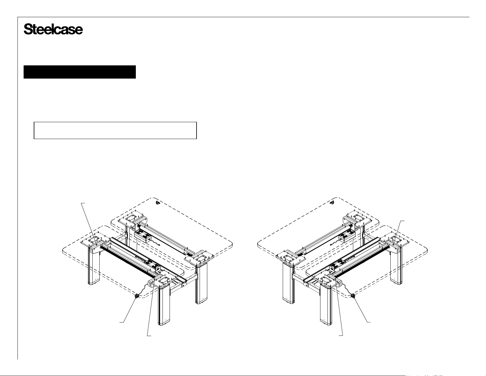
Series 5 Table Assembly
Determine Switch Position on your Table
• The switch can be located on either on either side of your table,
but the switch comes with a short cable to minimize clutter. So,
be sure to always locate the master motor near the switch loc ation.
NOTE: It does not matter which side of the table the master or
slave motor goes on.
SLAVE MOTOR
SWITCH
Switch & Master Motor on Right:
MASTER MOTOR
Switch & Master Motor on Left:
SLAVE MOTOR
SWITCH
MASTER MOTOR
Page 8 of 38
939564909 Rev B
®
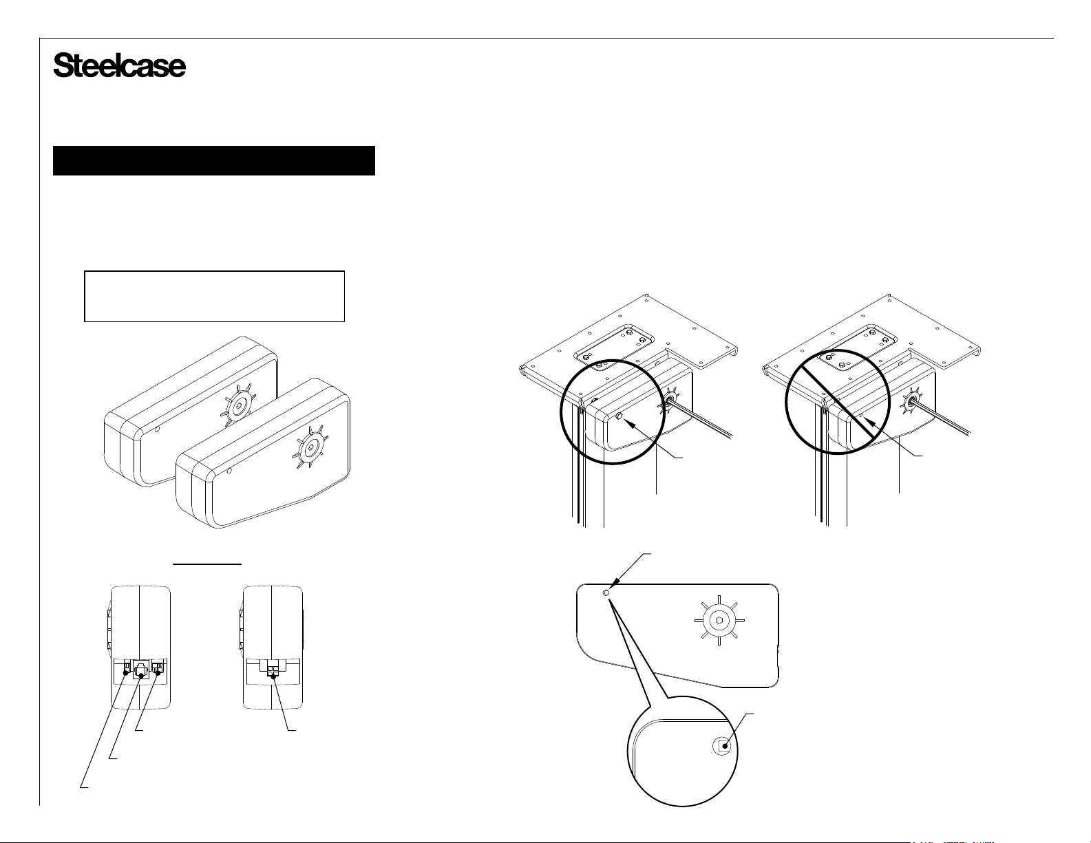
Series 5 Table Assembly (cont.)
Identify the Master and Slave Motors
The master motor and slave motor look the same,
except for the connection panel at the back.
NOTE: The power supply converts 120V AC
from the wall outlet to 24V DC. The series 5
motors operate on 24V DC.
Slave
Rear View
Master
Slave
Master
IMPORTANT! The master motor has one other key difference.
It also has a hidden kill switch. This kill switch is inside the
front mounting hole. If the front mounting bolt is not properly
installed, the table will not operate!
CORRECT!
FRONT MOUNTING HOLE
(Table will not operate)
MOUNTING
BOLT
WRONG!
NO MOUNTING
BOLT
4-WIRE CONNECTOR
TO SLAVE MOTOR
RJ-11 SOCKET
FROM SWITCH
2-WIRE CONNECTOR
FROM POWER SUPPLY
KILL SWITCH
SINGLE 4-WIRE
CONNECTOR FROM
MASTER MOTOR
Page 9 of 38
939564909 Rev B

®
Series 5 Table Assembly (cont.)
Installing Driveshafts
Driveshafts are retained using cap nuts, which
grip the driveshaft ends and prevent them from
backing out of the lifting columns.
Tables require one cap nut mounted outside of
each lifting column. The driveshaft assembly is
thus retained in both directions.
Place cap nut on a flat, hard surface and push
1
driveshaft into it.
With lifting columns pushed all the way down, feed
2
driveshaft through each lifting column, from outside,
until cap nut bottoms out on each lifting column.
CAP NUT
(with plastic cover)
CAP
NUT
1
CAP
NUT
FINISHED ASSEMBLY
2
Page 10 of 38
939564909 Rev B
®
Series 5 Table Assembly (cont.)
Installing Driveshafts (cont.)
Determine on which side of the table
3
each motor will go. (see page 16)
Install M6 x 80 bolts & M6 nuts to
each motor as shown.
Driveshafts and Lifting Column Synchronization
4
Series 5 lifting columns and motors must be synchronized
before installing the driveshafts.
Series 5 motors are shipped from the factory in the
"all the way down" position.
Before inserting the driveshafts, ensure ALL
LIFTING COLUMNS are pushed all the way down
(fully compressed).
Insert the exposed stud from each motor
5
into the side mounting slot of the outboard
leg mounting plates.
Example: Master motor and switch
on user's right-hand side.
Master Motor
3
10mm M6 HEX NUT
Slave Motor
10mm M6 x 80 HEX HEAD BOLT
4
5
EXPOSED STUD
MOTOR
MOTOR
Page 11 of 38
939564909 Rev B
®
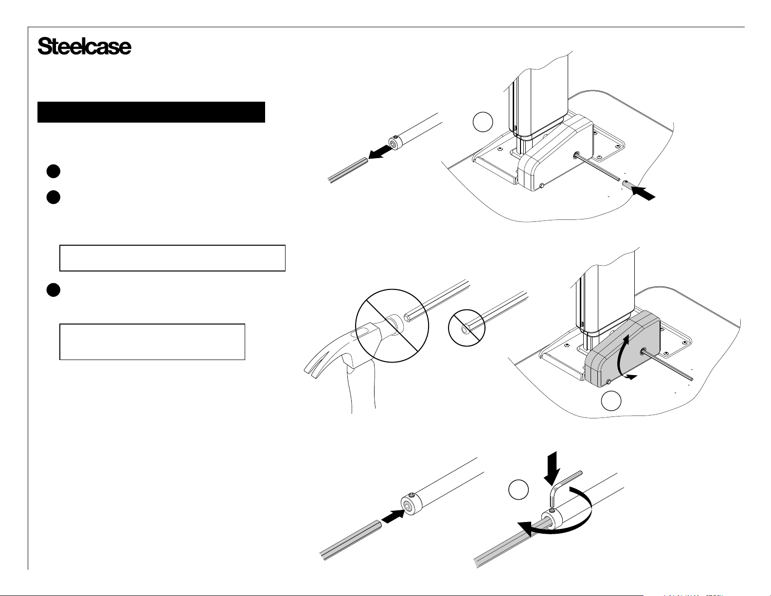
Series 5 Table Assembly (cont.)
Installing Driveshafts (cont.)
Insert hex shafts into driveshaft tube.
6a
If the hexagon openings are not perfectly aligned,
6b
rotate the motor up and down to align the hex
shaft with the driveshaft tube, until the driveshaft
slides through with ease.
NOTE: DO NOT pound the hex shafts through with a
hammer. This will mushroom the end of the hex shaft.
Ensure all driveshafts are inserted into driveshaft
6c
tubes. Tighten set screws very tightly with
a 3mm hex wrench.
NOTE: DO NOT overtighten the set screws.
Overtightening can strip the threads in the
driveshaft tube.
6a
6c
6b
Page 12 of 38
939564909 Rev B
 Loading...