

Steelcase 7 series Troubleshooting Manual
IMPORTANT NOTE: This guide applies to models shipped prior to December 2015 only.
Troubleshooting Guide
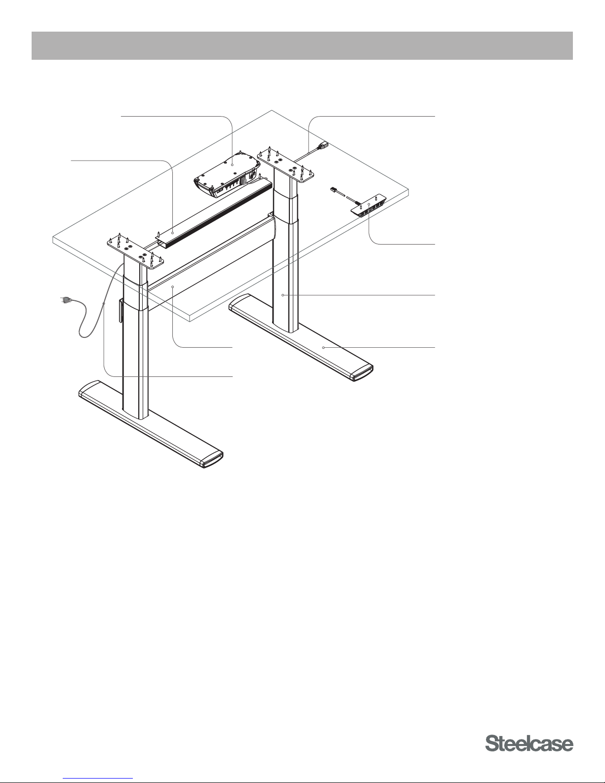
Cable Manager
Control Box
(PRE-DECEMBER 2015)
Low-Voltage Cable
Controller
Lifting Column
Stretcher Foot
Power Cable
SERIES 7 TABLES
PRE-DECEMBER 2015
HOW THEY WORK
• Each Lifting Column contains an individual motorized lift mechanism.
• The Control Box contains a power transformer. This converts high-voltage AC current from the wall outlet
(120v or 240v) to low-voltage 18v DC current, which powers the Lifting Columns.
• Only the main power cable carries high voltage. All other cables carry low voltage.
• The Control Box contains a computer processor with embedded software controllers.
• The Control Box controls all aspects of Table motion, and synchronizes motion of the individual Lifting Columns.
• The Control Box will shut down the entire table if a fault is detected. For example, if one Lifting Column
is binding or trapped, it will draw significantly more current than the other Lifting Column, and the Control
Box will shut down the entire Table to prevent further damage.
• The Controller is the user interface to the Table, and directs all Table movements via the Up-Down buttons
and the Preset buttons.
• Preset data is stored in the Controller itself, not in the Control Box.
Published 3/2016

IMPORTANT NOTE: This guide applies to models shipped prior to December 2015 only.
READ THE ASSEMBLY DIRECTIONS AND USER GUIDE
Many times, problems can be the result of improper assembly. Reference the Assembly Directions
document to ensure the Table is assembled correctly. If so, reference the troubleshooting steps throughout
this document.
TROUBLESHOOTING PARTS KIT
Having a spare part that is known to work will quickly lead to accurate identification of faulty components.
Without this, it can be little more than guesswork.
Steelcase strongly recommends that every Dealer maintain a small kit of parts for troubleshooting purposes.
This kit of parts should include: Table
1. Lifting Column qty=2 Service Part no. 003072DSR
2. Control Box qty=1 Service Part no. 003071DSR
3. Controller (digital) qty=1 Service Part no. 005291DSR
4. Low-Voltage Cable (2m) qty=2 Service Part no. 003067DSR
5. Power Cable qty=1 Service Part no. 003068DSR
Always maintain a complete kit of troubleshooting spare parts that are known to work properly, to quickly
identify the root cause of problems and resolve customer issues on the first try.
TROUBLESHOOTING STEPS
Step 1: Check for power at the wall outlet; ensure the Table is properly assembled, and all cables are
securely connected.
Step 2: Check all connections of Low-Voltage Cables: are any of the pins in the connectors damaged or
not making contact? (see Fig. 2 on page 5)
Step 3: Obtain a Control Box, Controller, Power Cable and Low-Voltage Cable that are known to work.
Step 4: Using the known good components, test the Lifting Columns one by one. (see Common
Procedures) Replace any faulty Lifting Columns.
Between each of the following steps, be sure to initialize the Control Box. (see Common Procedures)
Step 5: If Lifting Columns operate properly, progressively swap out parts in the test setup as follows:
A. Swap the known-good Power Cable with the original from the non-functioning Table.
If it stops working, the Power Cable is faulty.
B. Using the original Power Cable, swap the known-good, Low-Voltage Cable with the original
from the non-functioning Table. If it stops working, the Low-Voltage Cable is faulty.
C. Using the original Power and Low-Voltage Cables, swap the known-good Controller with
the original from the non-functioning Table. If it stops working, the Controller is faulty.
D. Using the original Power and Low-Voltage Cables, and the Controller, swap the known-good
Control Box with the original from the non-functioning Table. If it stops working, the Control
Box is faulty.
Be sure to go through all of the steps above to fully identify all faulty components.
There could be more than one!
2

IMPORTANT NOTE: This guide applies to models shipped prior to December 2015 only.
COMMON PROCEDURES
POWER-SAVING CONTROL BOX:
• The Control Box automatically powers down into ‘Standby’ mode after approximately 10 seconds of inactivity.
• During Standby mode, the Control Box only consumes 0.1 watt of power.
• With the Control Box in Standby mode, the Table can lose power without affecting the synchronization
of the Lifting Columns.
• However, if the Control Box is still active and not in Standby mode, a power loss will require that the Lifting
Columns be re-synchronized.
• Power fluctuations and brownouts can also cause the need for re-synchronization.
Note: The Control Box does not reset (initialize) by being unplugged and plugged back in.
Refer to the Initialization procedure below.
INITIALIZING THE CONTROL BOX:
• In the unlikely event that an error occurs, press and hold the Up-Down buttons simultaneously
for 5 seconds to reset the Control Box.
• Synchronize the Lifting Columns as outlined below.
SYNCHRONIZE THE LIFTING COLUMNS:
• Operate the table all the way down to the lowest position, and release the Down button.
• Press the Down button again, and hold.
• After a few seconds, the Table will visibly move up and down, settling to its correct “bottom” position.
• The Lifting Columns are now synchronized via the software in the Control Box.
• Operate the Table all the way up and down to confirm proper function.
TEST INDIVIDUAL LIFTING COLUMNS:
• Lifting Columns can be operated individually, even if they are not assembled to a table.
• Obtain a Control Box that is known to work. Be sure the Control Box is unplugged, or plugged in but
in Standby mode.
• Connect the Low-Voltage Cable of the targeted Lifting Column to the known-good Control Box.
Connect only to Port/Channel 1. (farthest from the Power Cable)
• Obtain a Controller that is known to work, and connect it to the Control Box.
• If the Control Box is unplugged from the wall outlet, plug the Power Cable back in.
• With the system hot, operate the individual Lifting Column.
A. Can the Lifting Column be operated through its full range of motion?
B. Does the Lifting Column appear to function normally?
Caution! If the Lifting Column is assembled to a table, first flip the table upside-down and remove
Stretcher. This will allow full and free motion of the targeted Lifting Column, and will prevent damage
to the Stretcher and Lifting Column.
Any faulty Lifting Columns must be replaced.
There are no field-serviceable parts inside the Lifting Column.
OBTAINING REPLACEMENT PARTS
Contact your local Steelcase dealer to help identify and order Service Parts.
If you need help, call 888.STEELCASE.
3
 Loading...