

Steelcase 5, A5BQ, A5JL, A5CQ, A5JR Series Manual
...
®
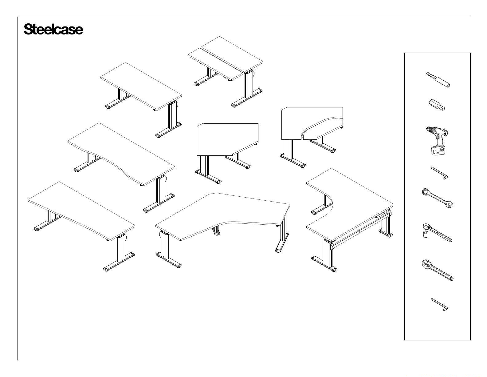
Series 5 Adjustable Height Tables
#2
M3
888.STEELCASE (888.783.3522)
www.steelcase.com
©
2018 Steelcase Inc.
Grand Rapids, MI 49501
U.S.A.
10mm & 14mm
10mm
2.5mm
Page 1 of 35
004231D Rev T
®
Max.
Min.
X
X
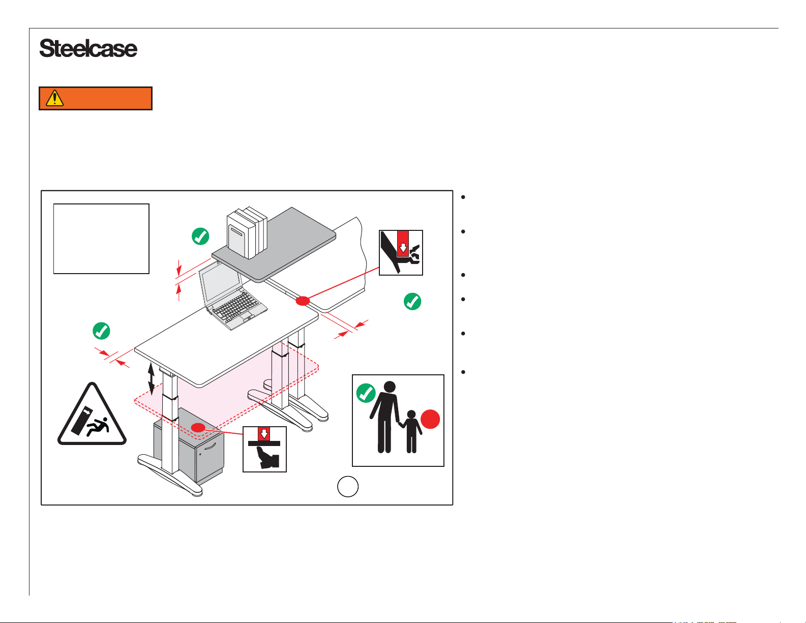
WARNING
This powered, adjustable height desk appliance is not intended for use by persons (including children) with reduced physical, sensory or mental capabilities, or lack
of experience and knowledge, unless they have been given supervision or instruction concerning use of the appliance by a person responsible for their safety.
Children should be supervised to ensure that they do not play with the appliance.
NOTE: Desk image
is for reference only.
Table shape and leg
quantity may change
based on the style
and configuration.
>1"
(25mm)
RISK OF SERIOUS INJURY DUE TO PINCH POINTS, TIPOVER, OR POTENTIAL COLLAPSE.
RISK OF DEATH OR SERIOUS INJURY. Raising or lowering desk can
trap, pinch or crush body parts or property.
CRUSH HAZARD - DO NOT PLACE FEET, LEGS OR OTHER BODY
>1"
(25mm)
>1"
(25mm)
X
PARTS ON OBJECTS PLACED UNDER TABLE TOP OR BELOW
MODESTY PANEL.
DO NOT OPERATE THIS EQUIPMENT Unless Properly Trained.
DO NOT ALLOW USE BY CHILDREN or people unable to understand
the risks and to safely adjust the desk height.
INSPECT REGULARLY. Stop using if product is damaged or has
loose parts. Only repair with Steelcase authorized parts and methods.
MAINTAIN >1” (25mm) GAP ABOVE OBJECTS ON DESK AT MAX
HIEGHT AND BETWEEN THE DESK & ADJACENT OBJECTS.
Locate desk, accessories, and nearby objects to allow movement of
desktop through full range without pulling cords, trapping body parts,
or colliding with anything (shelves, electrical plugs and cords, door
knobs, window sills, storage cabinets, etc.)
1/888.783.3522
?
www.steelcase.com
Page 2 of 35
004231D Rev T
®
POTENTIAL FOR INJURY
: The use of worksurfaces that do not comply with the Steelcase defined criteria and limitations could cause personal injury or p
roperty damage due to pinch
points, instabilit
y
, or other problems.
POTENTIAL FOR NON-COMPLIANCE: The use of work surfaces that do not comply with Steelcase criteria VOIDS any Steelcase claims of
compliance with ANSI/BIFMA, UL, LEED,
or other applicable requirements. The use of non-Steelcase work surfaces on Steelcase adjustable-height bases may NOT be accept
ed as compliant to municipal electrical codes or
OSHA federal workplace standards, because this use does not create an NRTL (UL, ETL, etc.) listed product.
Steelcase is not responsible for the ultimate determinations of compliance
for height-adjustable bases with non-Steelcase work surfaces. Steelcase assumes NO liability for lack of standards compliance
in these instances.
BASE-ONLY
WARNING
WARRANTY RESTRICTIONS: The use of non-Steelcase supplied work surfaces VOIDS all Steelcase warranties, expressed or implied.
DISCLAIMER: The use of non-Steelcase work surfaces is NOT recommended. Any use of a non-Steelcase work surface requires additional investigation by the customer regarding the
appropriateness for use. It is the sole responsibility of the customer to determine the suitability and safety of the selected work surface construction and attachment means. The following
information is provided as a guideline, but does not address all potential issues. Customers should seek professional guidance as to the appropriateness of their chosen work surface.
MANDATORY REQUIREMENTS REGARDLESS OF WORK SURFACE MATERIAL OR CONSTRUCTION:
FASTENERS: Adjustable-height bases include fasteners intended for use with Steelcase work surfaces.
These fasteners may potentially also be suitable for work surfaces meeting the following criteria:
Medium-density or higher particleboard or fiberboard cores with High-pressure laminate (HPL), Low pressure laminate (LPL) or veneer & backers
Thickness of .984” (25.0 mm) or greater
Fasteners located a minimum distance of .984” (25.0 mm) from any edge
Any other work surface construction will require different and/or additional fastening means and these means
must be determined by the project’s designer, architect, or engineer. For example, solid-surface materials
should use appropriate threaded inserts and corresponding fasteners or similar attachment means.
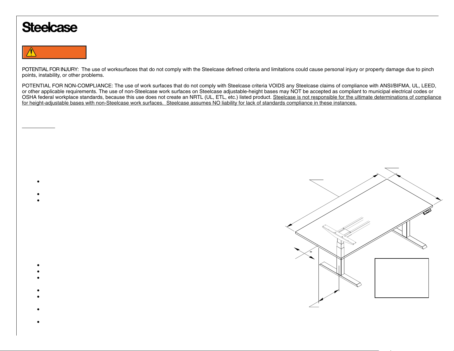
RISK OF SERIOUS INJURY:
WORKSURFACE
DEPTH
WORKSURFACE
WIDTH
In all cases, all fastener locations provided in the base attachment features MUST be used (e.g. if attachment
cantilever has 6 screw holes, all 6 holes must be used for attachment).
DIMENSIONAL LIMITATIONS:
Work surface depth not to exceed 36.0” (914.4 mm)
Longitudinal work surface position on base must be on centerline ± 2.0” (50.8 mm)
Work surface overhang (distance from side of support cantilever to edge of work surface) must be
greater than .984” (25.0mm) and may not exceed 15.0” (381 mm)
Work surface overhangs larger than .984” (25.0mm) are not allowed on widths < 64.0” (1625.6 mm)
Work surface overhangs between .984” (25.0mm) and 15.0” (381 mm) may exist on one side only for
tops that are ≥ 64.0” (1625.6 mm) and ≤ 71.645” (1820.8 mm)
Work surfaces larger than 71.685” (1820.8 mm) must have overhangs larger than .984” (25.0mm) on
at least one side, but may not exceed 15.0” (381 mm) on any side
Maximum work surface width may not exceed 101.685” (2582.8 mm)
+
C
L
FOLLOW ALL WARNINGS PROVIDED FOR BASE + WORK SURFACE.
NOTE: Desk image
is for reference only.
Table shape and leg
quantity may change
based on the style
and configuration.
WORKSURFACE
OVERHANG
Page 3 of 35
004231D Rev T
®
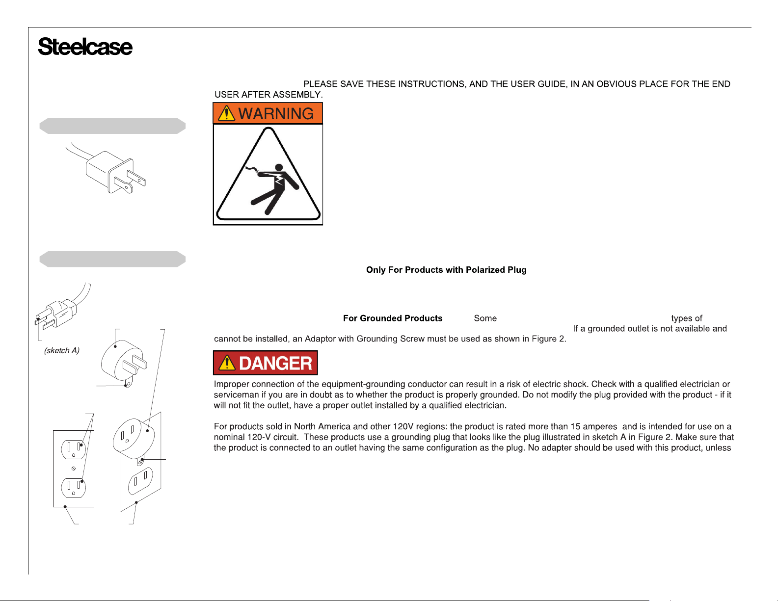
Products with Polarized Plugs
Figure 1
Polarized Plug
Products with Grounded Plugs
IMPORTANT SAFETY INSTRUCTIONS
When using an electrical furnishing, basic precautions should always be followed, including the following: Read all instructions before
using (this furnishing).
1. Always unplug this furnishing from the electrical outlet before cleaning.
2. Use this table only for its intended use as described in these instructions. Do not use attachments not
recommended by the manufacturer.
3. Never operate this table if it has a damaged cord or plug, if it is not working properly, or if it has been
dropped or damaged.
4. Keep the cord away from heated surfaces.
5. Never drop or insert any object into any opening.
6. Do not use outdoors.
7. Do not operate where aerosol (spray) products are being used or where oxygen is being
administered.
8. For loading always put heavier items at the bottom and not near the top in order to help prevent the
possibility of the furnishing tipping over.
The desk or table shall be installed near power socket & the plug shall be easily accessible.
POLARIZED PLUG INSTRUCTIONS ( ) - To reduce the risk of electrical shock, some
furnishings have a polarized plug (one blade is wider than the other) like the plug illustrated in Figure 1. This plug will fit in a polarized
outlet only one way. If the plug does not fit fully in the outlet, reverse the plug. If it still does not fit, contact a qualified electrician to
install the proper outlet. Do not change the plug in any way.
GROUNDING PIN
TAB FOR
GROUNDING SCREW
GROUNDED
OUTLET
(A)
GROUNDED
OUTLET BOX
Figure 2
Grounding methods
ADAPTER
(B)
METAL
SCREW
GROUNDING INSTRUCTIONS (
appliances to a properly grounded outlet in accordance with all local codes and ordinances.
using the Adapter w Grounding Screw shown in illustration.
only) - products must be grounded. Connect these
PLUG ILLUSTRATION DISCLAIMER - The illustrations shown to the left show a plug typically seen in North America and other 120V
regions. Illustrations shown here may not match your product. Depending on your region, the plug pin size and shape may change.
OPERATING INSTRUCTIONS
Please refer to the provided User Guide, which is also available at www.steelcase.com
Page 4 of 35
004231D Rev T
®
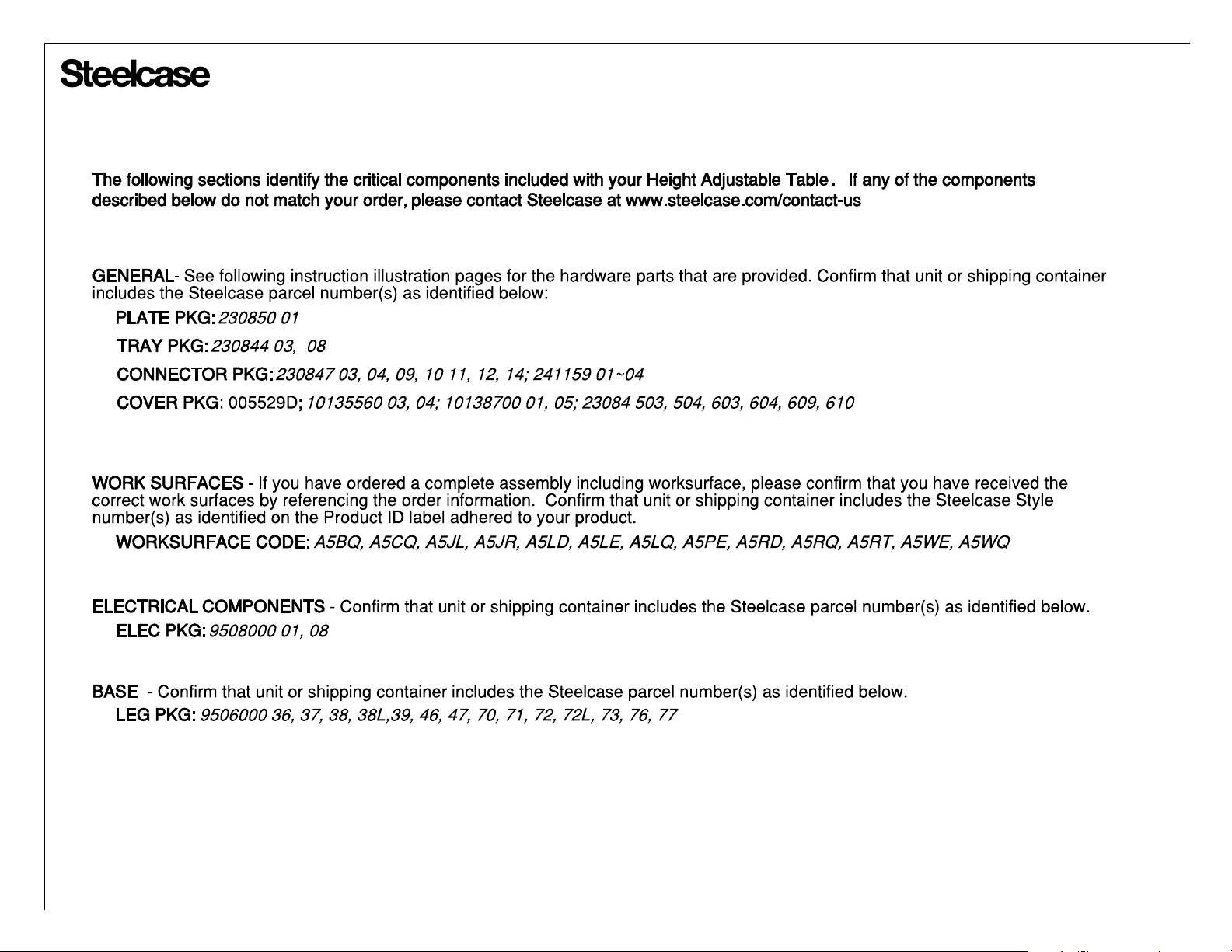
DRIVESHAFT PKG: 9506000 09~34DRIVESHAFT PKG: 9506000 09~34
Parts Provided
Page 5 of 35
004231D Rev T

®
TABLE OF CONTENTS:
PAGE(S):
Lets Get Started!.........................................................................................................
Which Legs Go Where?..............................................................................................
Determine Leg Positions on your Table......................................................................
Overhangs and Custom Leg Positions.......................................................................
Mounting Legs to Worksurfaces.................................................................................
Determine Switch Position on your Table...................................................................
o
Corner Tables.......................................................................................................
90
Left-Hand Tables.........................................................................................................
o
For 90
For 120
Tables.............................................................................................................
o
Tables...........................................................................................................
Identify the Primary and Secondary Motors..........................................................................
Installing Motors and Synchronizing Legs...................................................................
Driveshafts and Leg Synchronization..........................................................................
Installing Driveshafts...................................................................................................
Installing Switch & Power Supply................................................................................
Attach Driveshaft Covers and Wire Managers............................................................
Installing Stretchers....................................................................................................
Connect and Route All Cables....................................................................................
Finishing the Table Assembly......................................................................................
Appendix A: 2-Piece Worksurface Assembly..............................................................
Appendix B: Installing a Keyboard Mechanism for Bi-Level Worksurfaces................
6
7
8
8
9
10
11
12
13
13
14
15
15
16 through 19
20
21
22 & 23
24
25
26 & 27
28 through 34
Overview of Assembly Process
1) Decide on the table configuration.
2) Assemble 2-piece worksurface or bi-level mechanism (if applicable).
3) Attach legs to worksurface (with worksurface upside-down).
4) Assemble motors, power supply, and gearbox (if applicable).
5) Synchronize legs and add driveshaft(s).
6) Add stretcher(s) and decorative parts.
7) Add driveshaft cover(s) and wire manager(s).
8) Connect and route all cables, mount switch.
9) Flip table upright and test function.
10) Level and clean it up.
11)
PLEASE LEAVE THESE INSTRUCTIONS, AND THE USER GUIDE,
IN AN OBVIOUS PLACE FOR THE END USER AFTER ASSEMBLY.
Page 6 of 35
004231D Rev T
®
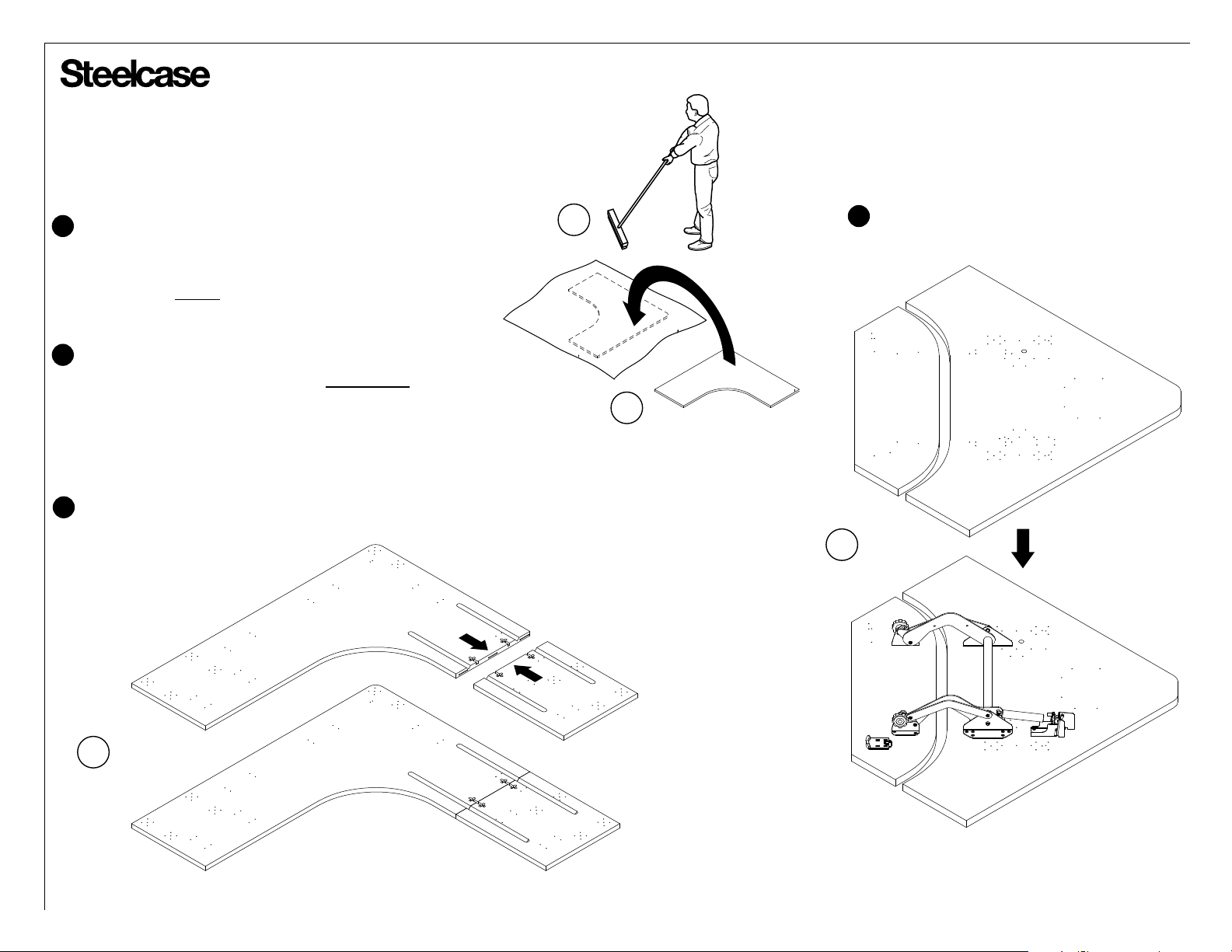
Let’s Get Started
Prepare a large open space to assemble the table.
1
• Sweep the floor! Screws and small parts can damage
the worksurface.
• Put down a CLEAN shipping blanket to protect the worksurface.
Unpack the worksurface and place on the shipping blanket upside -down.
2
• REMEMBER - You're looking at the UNDERSIDE of the worksurface.
Are you sure which side is left or right?
Assembling a monitor-keyboard worksurface with
1
2
4
a bi-level mechanism?
Jump to Appendix 'B' now.
Assembling a 90
3
worksurface?
3
o
corner table with a 2-piece
Jump to Appendix 'A' now.
4
Page 7 of 35
004231D Rev T
®
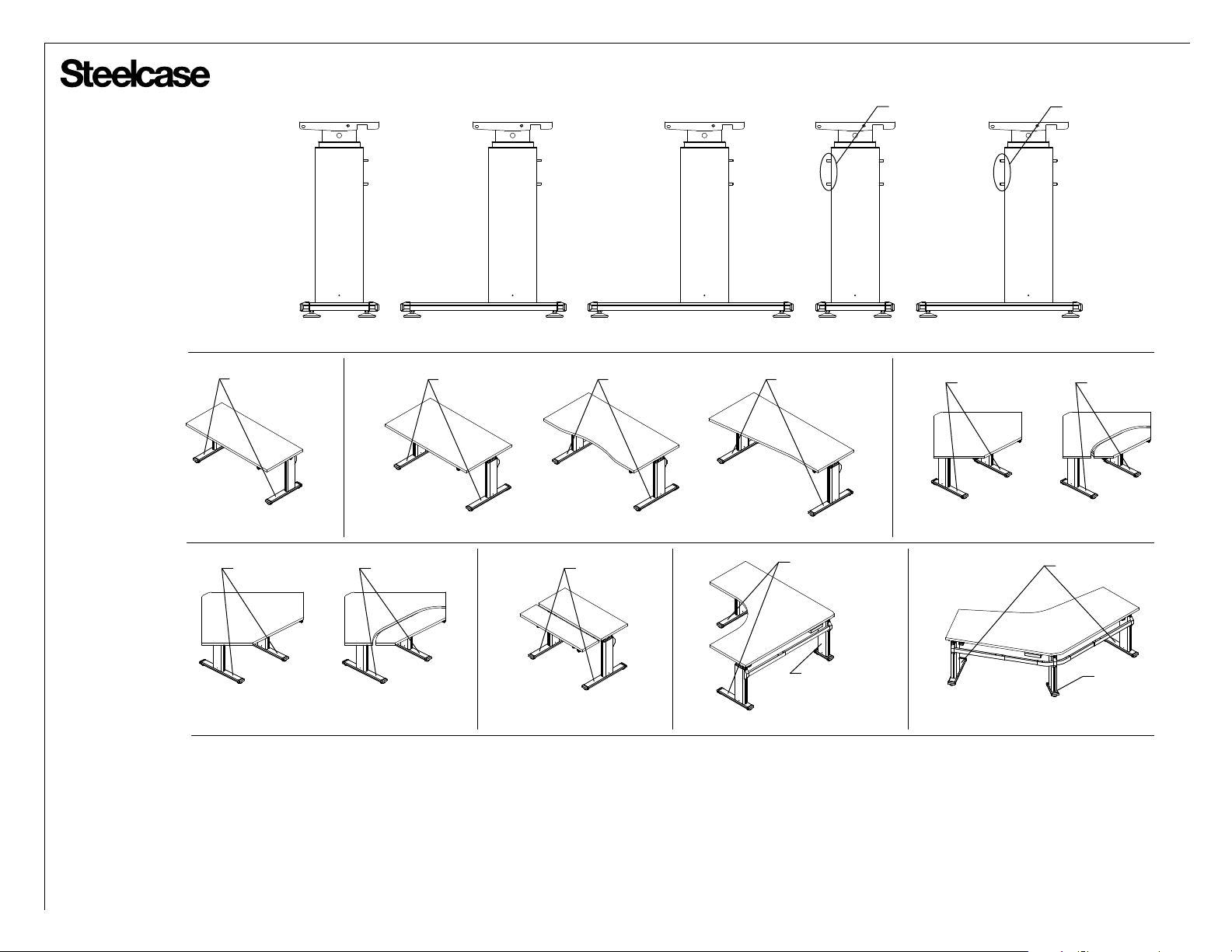
Which Legs Go Where?
Leg Types:
NOTE: Extra studs.
10" Standard 21" Standard 26" Standard 10" Corner 21" Corner
NOTE: Extra studs.
21" Std.
26" Std.
26" Std. 26" Std.
23"D Rectangle 29"D Rectangle Concave Taper-Flat
26" Std.
46" 90
26" Std.
o
46" 90o Bi-Level Rectangle Bi-Level 90o 3-Leg
26" Std.
21" Std.
10" Corner
21" Std. 21" Std.
o
40" 90
40" 90o Bi-Level
21" Std.
10" Std.
o
120
Page 8 of 35
004231D Rev T
®
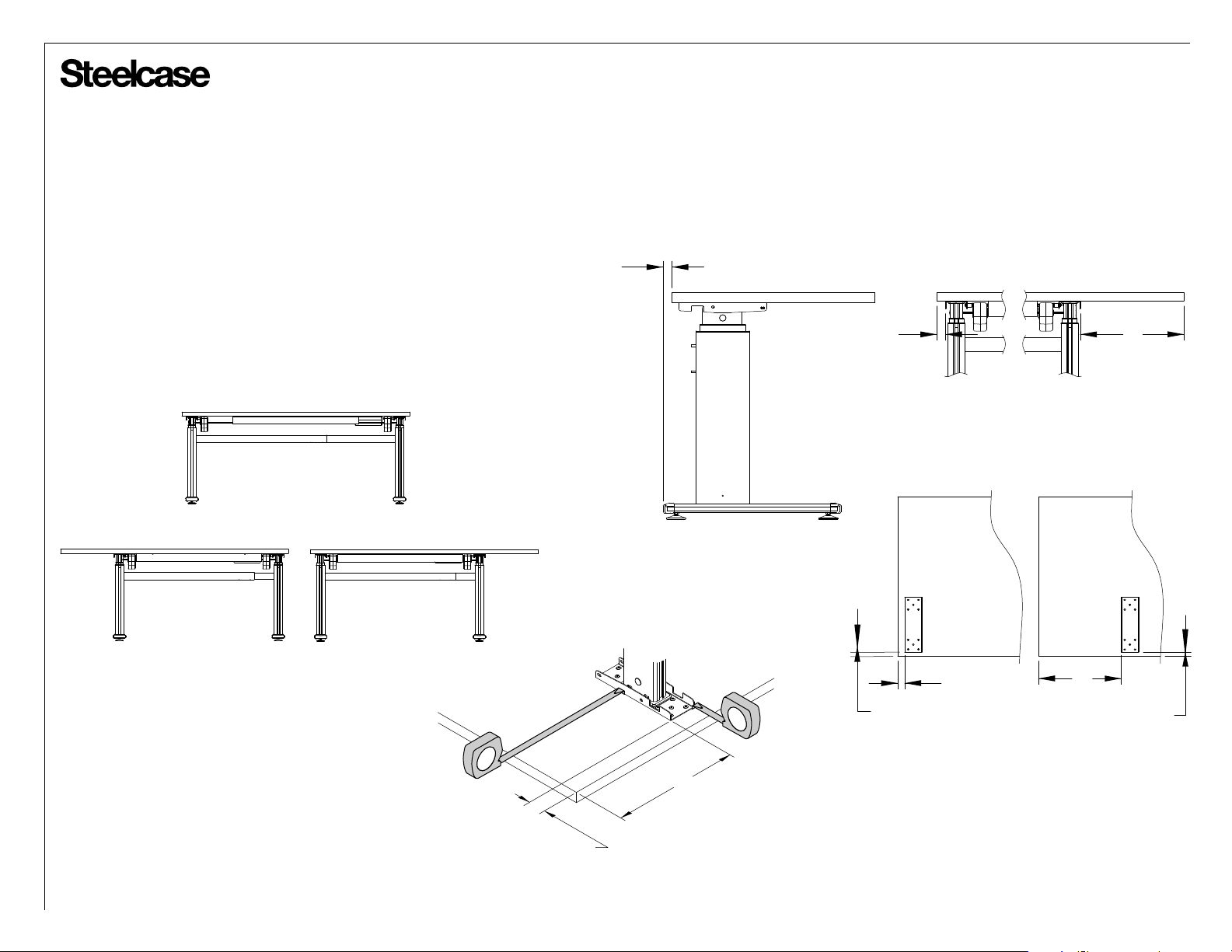
Determine Leg Positions on your Table:
• Many Series 5 tables allow multiple leg postions, providing flexibility to
maximize leg space, and allow overhangs for CPU slings and mo bile
pedestal placement.
• The smallest tables may not allow for larger worksurface overhangs.
(The standard overhang is 1-1/4".)
• The mid-size tables may allow for a single 15" overhang.
• The largest tables may be capable of allowing dual 15" overhangs.
(One on each side.)
• Refer to the specification guide for the capabilities of your specific table.
NO OVERHANGS
LEFT-HAND OVERHANG
RIGHT-HAND OVERHANG
Overhangs and Custom Leg Positions:
• There are pilot holes in worksurfaces that result in the standard
overhangs (1-1/4" and 15"), as well as a clearance at the back to
avoid pinch-points and provide for cable drop.
1"
CABLE
AND
PINCH-POINT
CLEARANCE
Side View:
1-1/4"
OVERHANG
Standard Mounting Plate Positions:
(Bottom View)
Front of Wksf.
(User Edge)
Front View:
15"
Front of Wksf.
(User Edge)
Legs may be mounted on the worksurface
in locations other than the factory default,
provided that:
• The overhangs DO NOT exceed 15".
• All screws are at least 1" from outside edges.
• All provided components still fit together (stretchers, driveshafts).
• No safety hazards are posed to the end users or installers.
(NO CABLE / PINCH-POINT
1.769"
CLEARANCE, BACK OF
FOOT FLUSH WITH BACK
OF WORKSURACE)
9"
CUSTOM
OVERHANG
0.769"
OFFSET
Back of Wksf.
1-1/4"
OVERHANG
Back of Wksf.
15"
OVERHANG
0.769"
OFFSET
Page 9 of 35
004231D Rev T
®
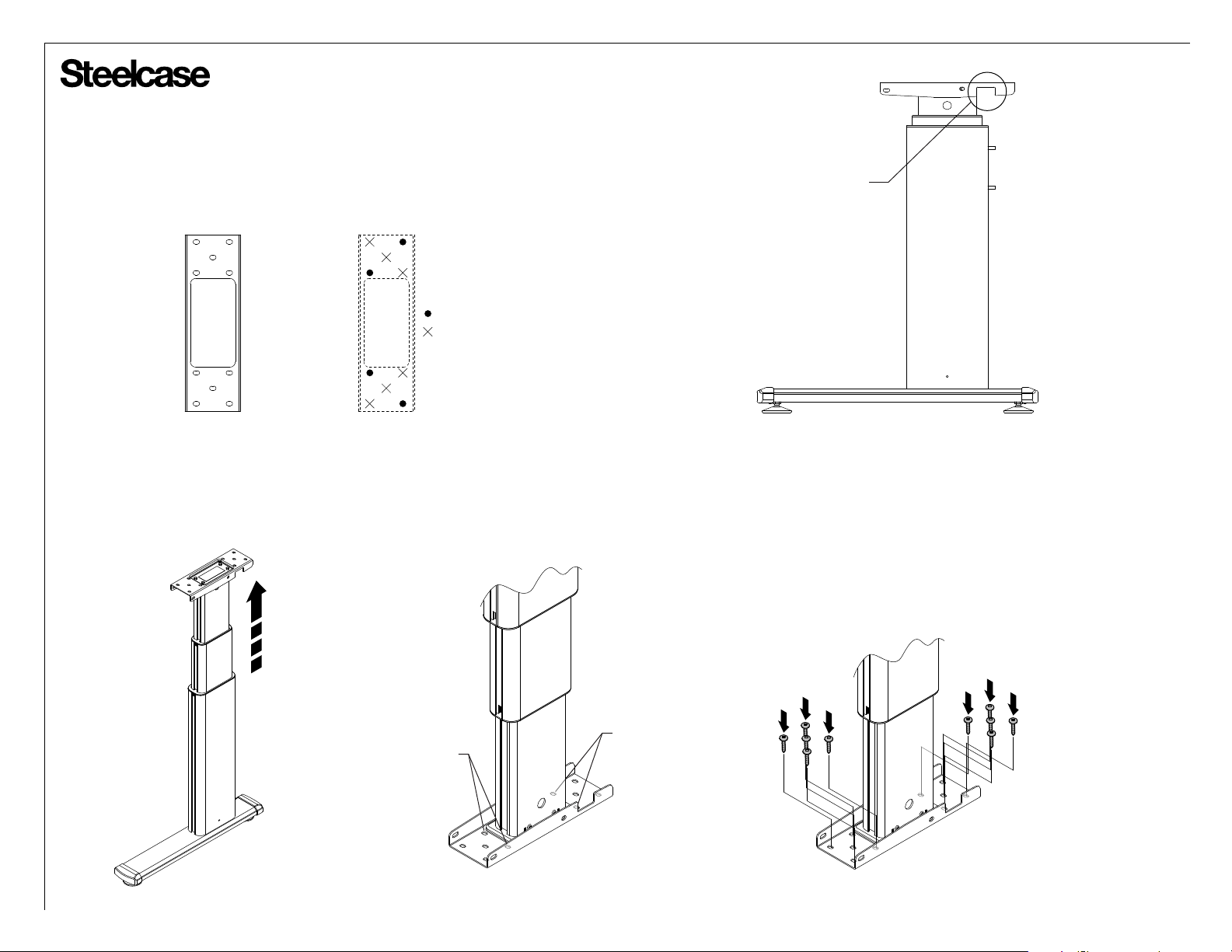
Mounting Legs to Worksurfaces
CAUTION: All holes in the leg mounting plates MUST
be filled with screws. Failure to install all
screws may result in structural instability.
Mounting Plate
Raise leg all the way up.
Worksurface
Pilot Holes
Raising leg allows access to the screws
adjacent to the inner column.
= PILOT HOLE
= NO PILOT HOLE PROVIDED
NOTCH IS ALWAYS
AT BACK OF LEG
(BACK OF TABLE)
Align each leg with the pilot holes in the desired
location, in the correct orientation. Attach each
leg with ten (10) of the provided #10 x 1.075 long
screws. These screws have a special drill-point,
making them easy to drive in without a pilot hole.
See step 10 on Page 18 for additional considerations
before finalizing the mounting of the legs.
FOR EASIER
ACCESS
FOR EASIER
ACCESS
Page 10 of 35
004231D Rev T
®
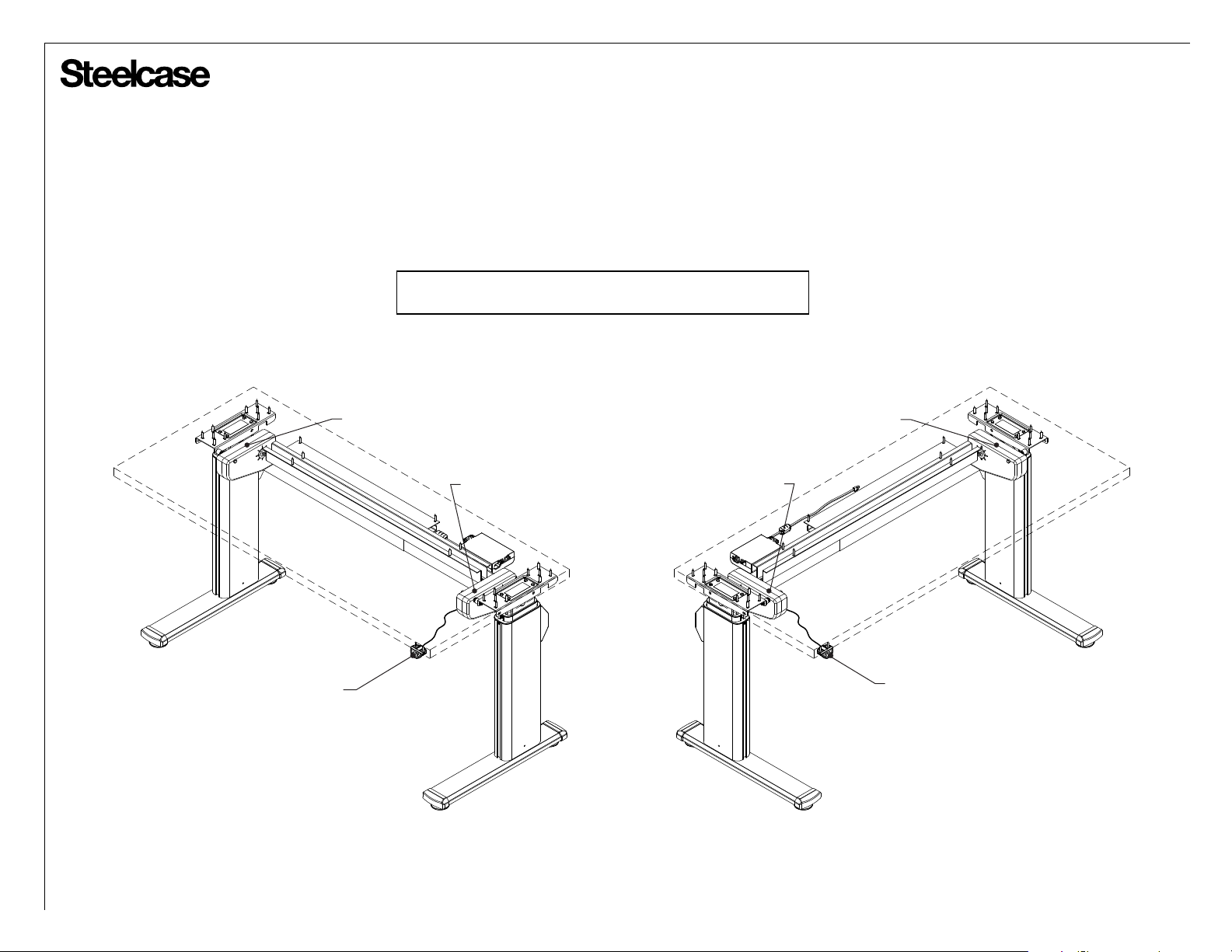
Determine Switch Position on your Table:
• The switch can be located on either side of your table, but the
switch comes with a short cable to minimize clutter. So, be sure
to always locate the primary motor near the switch location.
NOTE: It does not matter which side of the table the primary or
secondary motor goes on. This applies to all tables.
Switch & Primary Motor on Right:
SECONDARY MOTOR
SWITCH
PRIMARY MOTOR
Switch & Primary Motor on Left:
SECONDARY MOTOR
PRIMARY MOTOR
SWITCH
Page 11 of 35
004231D Rev T
 Loading...