

Page 1
Page 1 of 19
939546506 Rev E
R
A
Y
B
O
Index
Topic Page
Removal of the Seat Cushion 2
Installation of the Seat Cushion 3
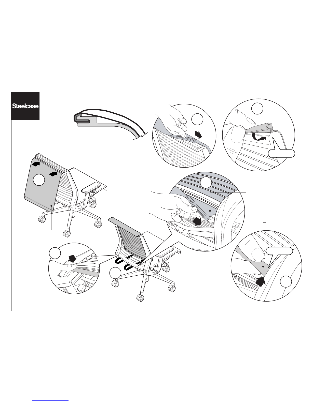
Removal of the Back Cushion 4
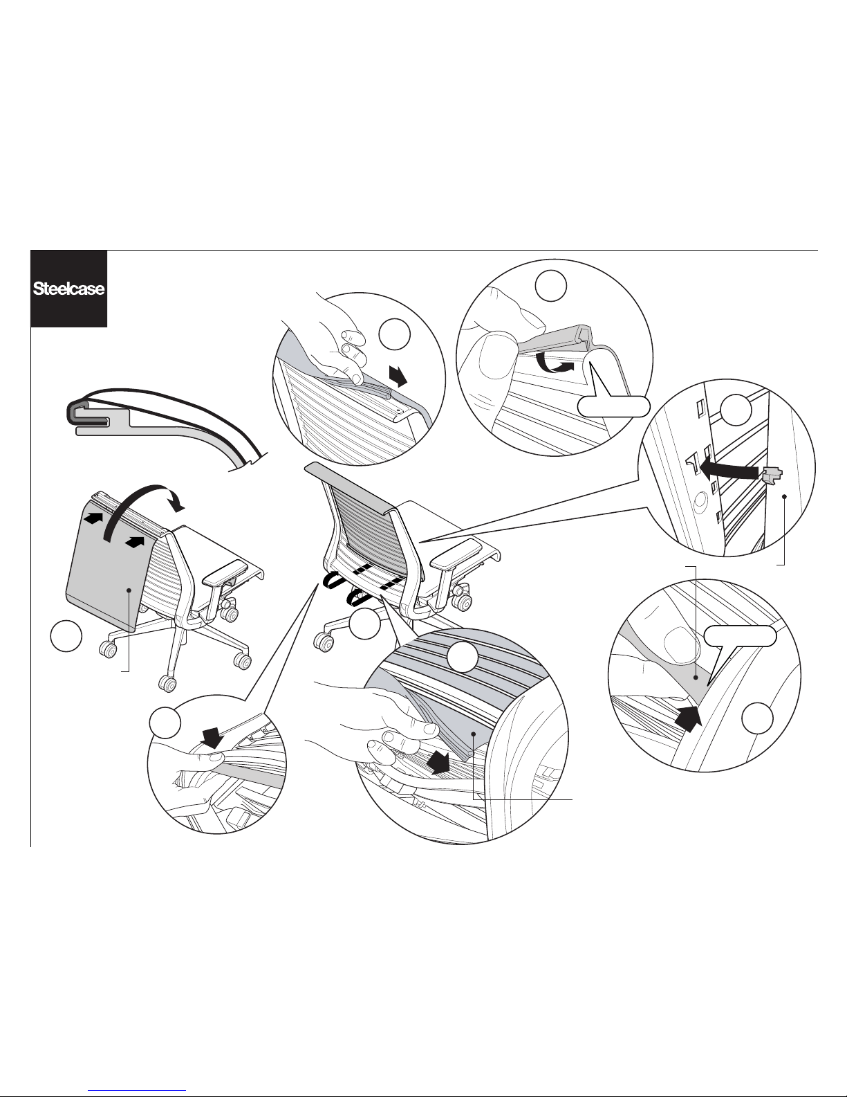
Installation of the Back Cushion 5
Removal & Installation of the 3D Knit Back Cushion 6
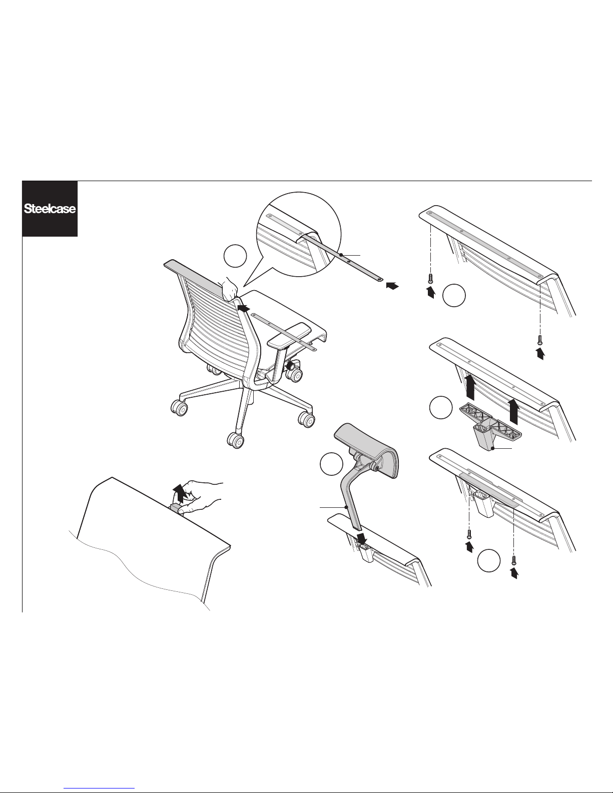
Installation of the Headrest 7
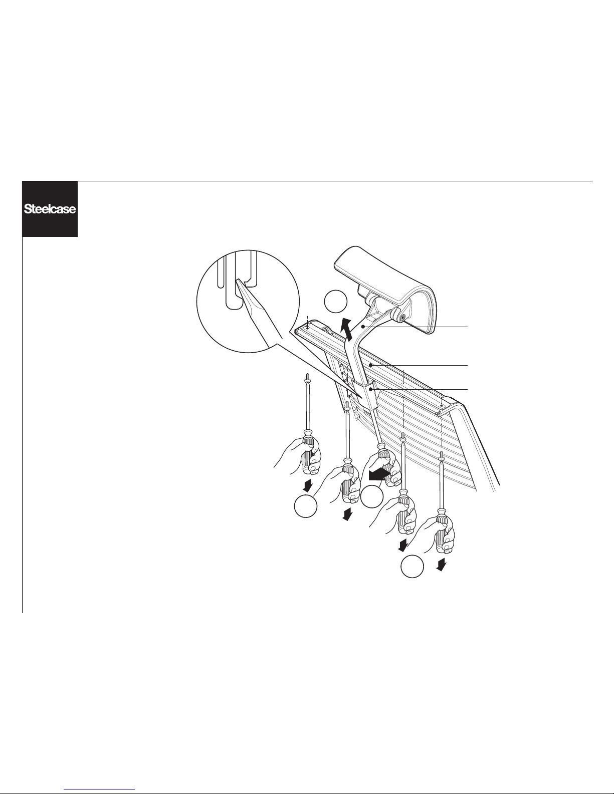
Removal of the Headrest 8
Removal & Installation of the Lumbar 9
Removal & Installation of the Back Frame 10
Removal & Installation of the Seat Frame 11
Removal & Installation of the Arms 12
Prior to October 3, 2005
Replacement of the Arm Cap 16
Removal & Installation of the Mechanism 17
Removal & Installation of the Base 18
Removal & Installation of the Pneumatic Cylinder 19
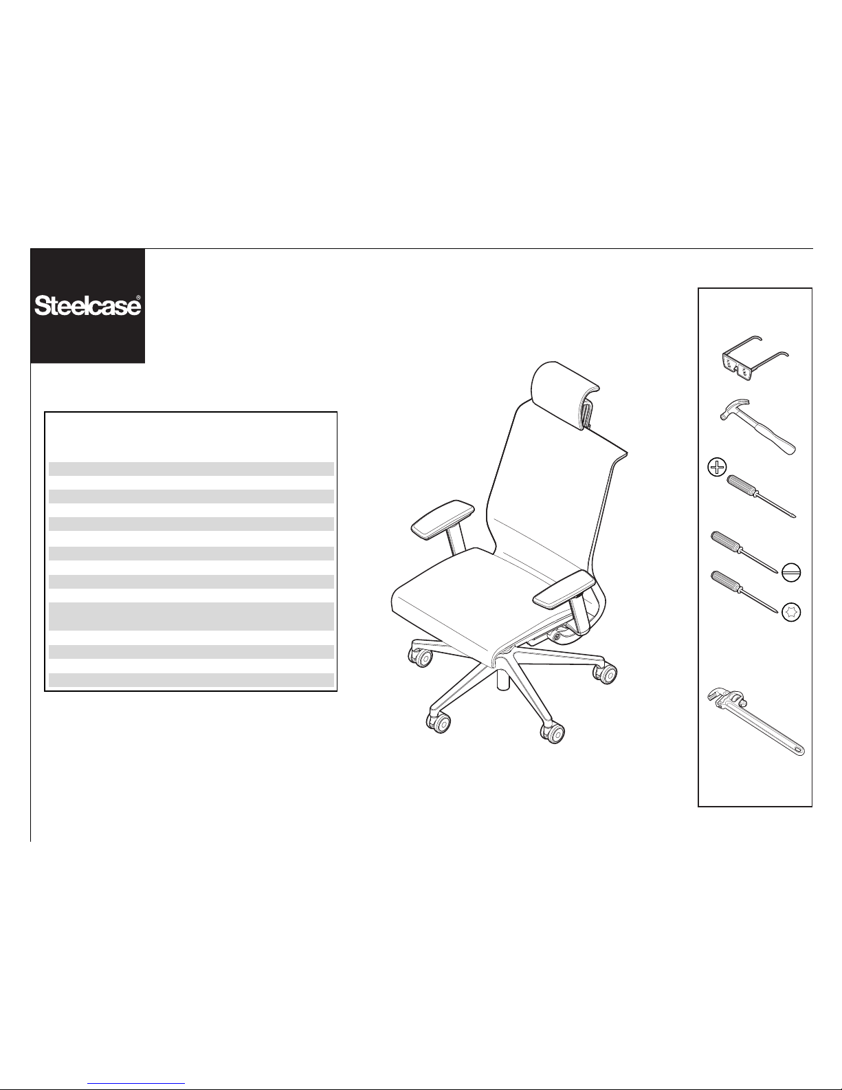
465 Think® for Customer Service
#2 and #3
Phillips
Torx
T15, T20 and T30
(An Allen wrench can
be subsituted if a torx
drive is not available)
If you have a problem, question, or request, call
your local dealer, or Steelcase Line 1 at
888.STEELCASE (888.783.3522)
for immediate action by people who want to help you.
(Outside the U.S.A., Canada, Mexico, Puerto Rico,
and the U.S. Virgin Islands, call: 1.616.247.2500)
Or visit our website: www.steelcase.com
©
2006 Steelcase Inc.
Grand Rapids, MI 49501
U.S.A.
Printed in U.S.A.
Page 2
Page 2 of 19
939546506 Rev E
4
3
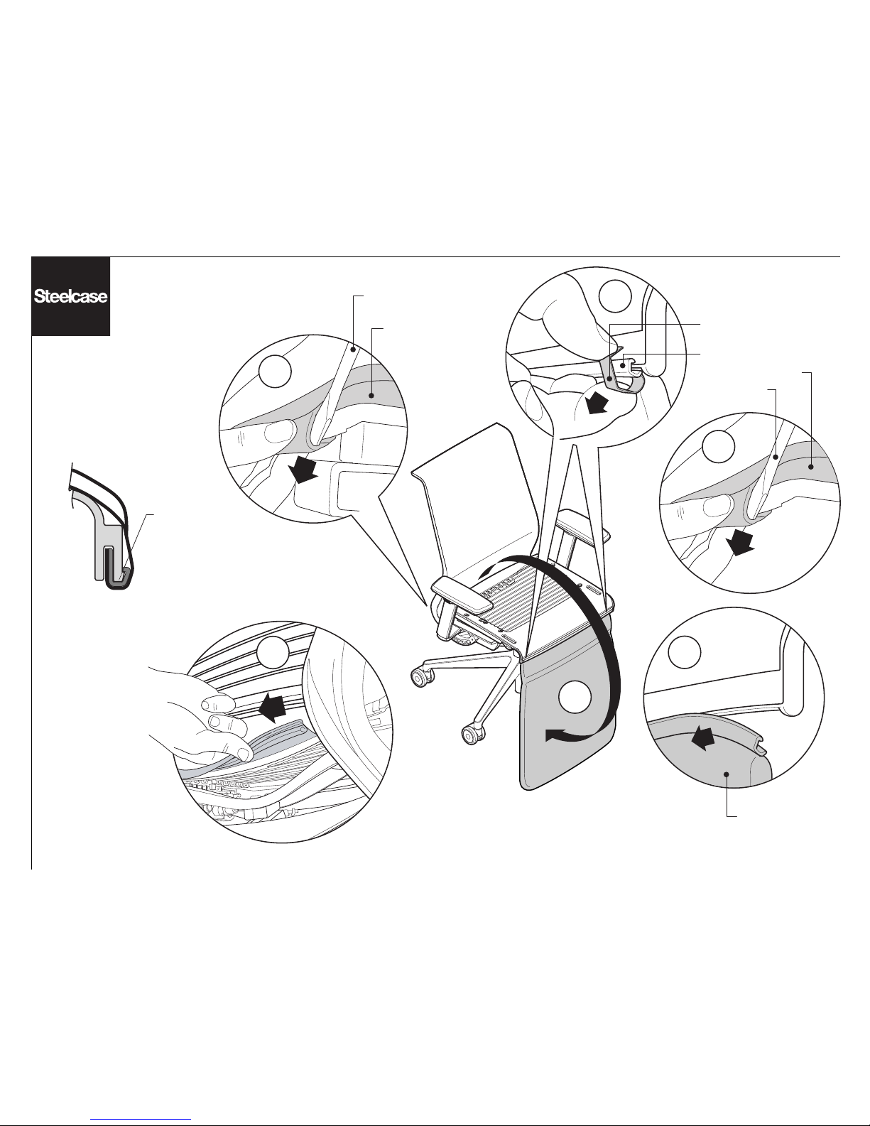
Removal of the
Seat Cushion
1
2
6
Side view of
cushion installed
START REMOVAL AT
BACK/REAR CORNER
OF THE SEAT.
CAREFULLY USE A
FLAT-BLADED
SCREWDRIVER TO
PUSH THE J-CHANNEL
OUT.
J-CHANNEL
RETAINER CLIP
SEAT CUSHION
FLAT-BLADED
SCREWDRIVER
SEAT CUSHION
5
FLAT-BLADED
SCREWDRIVER
SEAT CUSHION
J-CHANNEL
Page 3
Page 3 of 19
939546506 Rev E
2
Side view of
cushion installed
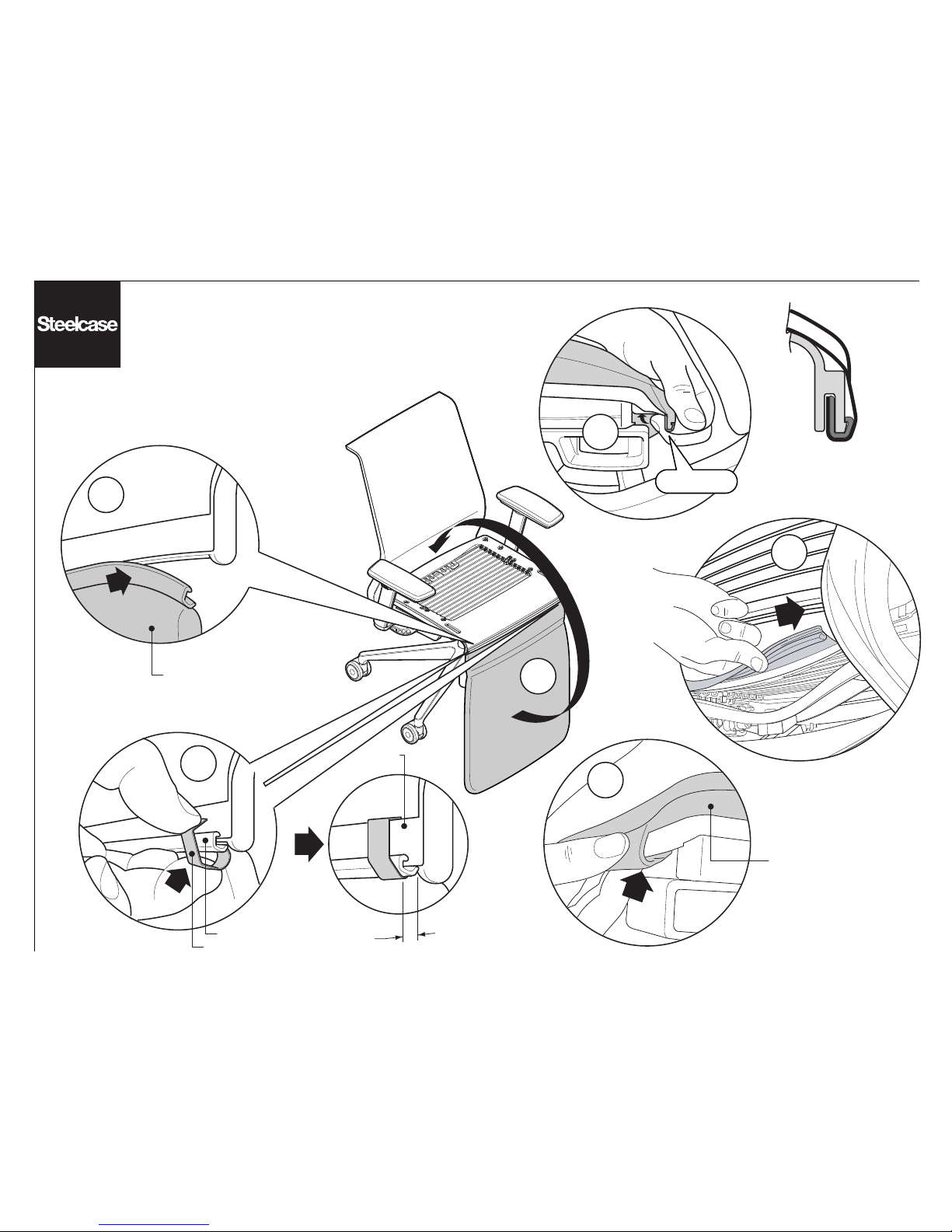
Installing the Seat Cushion
5
SEAT CUSHION
1
3
4
PLASTIC
RIB
1
4
"
/
6
SEAT CUSHION
J-CHANNEL
J-CHANNEL RETAINER CLIP
SNAP!
Page 4
Page 4 of 19
939546506 Rev E
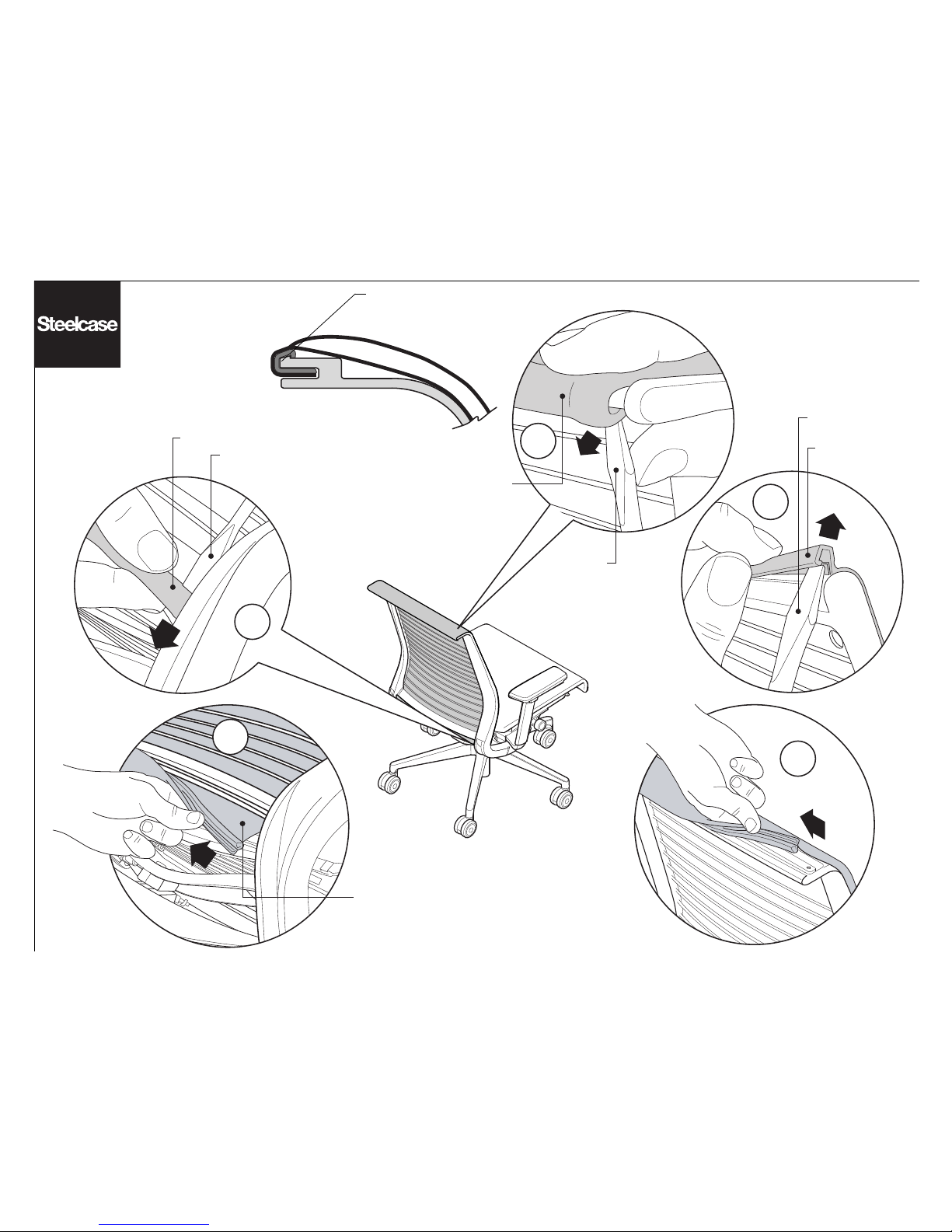
Removal of the Back Cushion
1
4
3
2
5
J-CHANNEL
BACK CUSHION
FLAT-BLADED
SCREWDRIVER
Side view of
cushion installed
START REMOVAL AT THE BOTTOM
CORNER OF THE BACK. CAREFULLY
USE A FLAT-BLADED SCREWDRIVER
TO PUSH THE J-CHANNEL OUT.
FLAT-BLADED
SCREWDRIVER
J-CHANNEL
J-CHANNEL
FLAT-BLADED
SCREWDRIVER
Page 5
4
Page 5 of 19
939546506 Rev E
1
3
7
BACK CUSHION
6
BACK CUSHION
Installing the Back Cushion
2
BACK CUSHION
5
Side view of
cushion installed
SNAP!
SNAP!
Page 6
Installation & Removal
of the 3D Knit Back Cushion
1
Page 6 of 19
939546506 Rev E
3
5
8
BACK CUSHION
2
BACK
CUSHION
6
4
7
BACK CUSHION
SNAP!
SNAP!
Side view of
cushion installed
3-D KNIT
BACK CUSHION
Page 7
1
2
4
3a
3b
Page 7 of 19
939546506 Rev E
Installation of the Headrest
1. Slide the headrest support
bracket under fabric into position.
NOTE: May be easier to remove
back cushion first.
2. Install two (2) outside screws
into headrest support bracket.
3. Mount headrest support with
two (2) inside screws.
4. Slide headrest arm assembly
into headrest support.
HEADREST ARM
ASSEMBLY
HEADREST
SUPPORT
HEADREST
SUPPORT
BRACKET
NOTE: If a shipping plug is located in the
headrest support, lift the plug out before
installing the headrest arm assembly.
Page 8
1b
1a
2
Page 8 of 19
939546506 Rev E
Removal of the Headrest
1. Place a flat-bladed screwdriver under
the headrest arm assembly and pry the
headrest support outward (1a) to allow
the headrest arm to slide out (1b).
2. Remove four (4) screws on the back
frame with a torx T20 screwdriver and
remove the headrest support bracket and
the headrest support.
Side View
HEADREST SUPPORT
HEADREST ARM
ASSEMBLY
HEADREST SUPPORT
BRACKET
2
Page 9
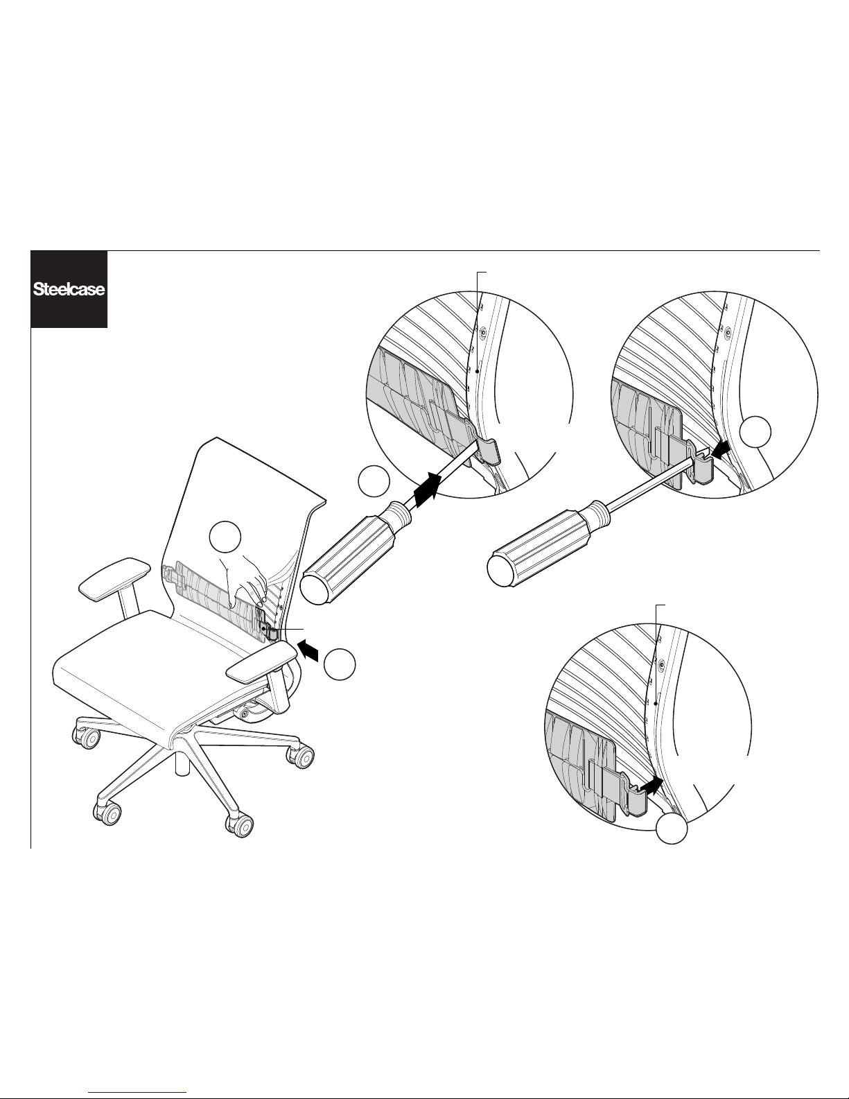
SLOTS
Removal & Installation
of the Lumbar
LUMBAR
Installation
Removal
SLOTS
1a
1b
1c
2a
2b
Page 9 of 19
939546506 Rev E
1. Slide the cushion over (1a).
Insert a flat bladed screwdriver
into the lumbar to release the
clip (1b). While the screwdriver
is still installed into the lumbar,
pull the lumber clip away from
the chair body (1c).
Repeat for the opposite side.
2. Slide the lumbar between the
back cushion and the wires (2a).
With your thumb, snap the lumber clip
into the slot in the chair body (2b).
Repeat for the opposite side.
TIP: Removed easiest
in the lowest position.
TIP: Installed easiest
in the lowest position.
Page 10
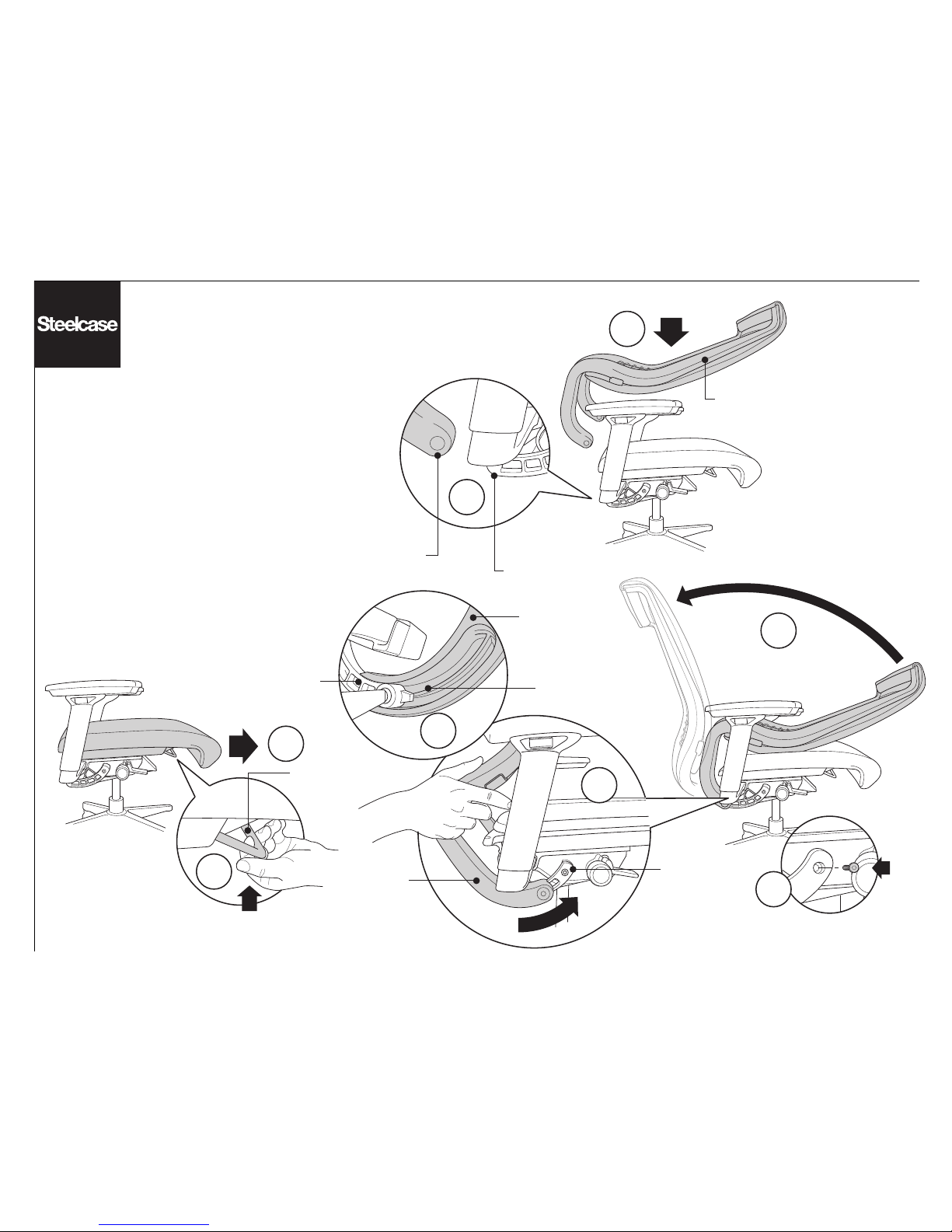
2a
2b
Page 10 of 19
939546506 Rev E
Removal & Installation
of the Back Frame
1. Lift seat slide lever (1a) and slide seat
forward all the way(1b).
2. Lay back frame onto seat cushion (2a)
and align backstops (2b). Holding onto the
bottom of the back frame, rotate back
frame (2c) and slide onto backstops (2d).
3. Install pivot screws, with a torx T30
screwdriver (or Allen wrench), on both
sides of the back frame.
Reverse to remove.
1b
1a
2c
2d
BACK STOP
BACK STOP
BACK STOP
BACK FRAME
BACK FRAME
BACK
FRAME
2d
3
GROOVE IN
BACK FRAME
BACK FRAME
SEAT SLIDE
LEVER
Page 11
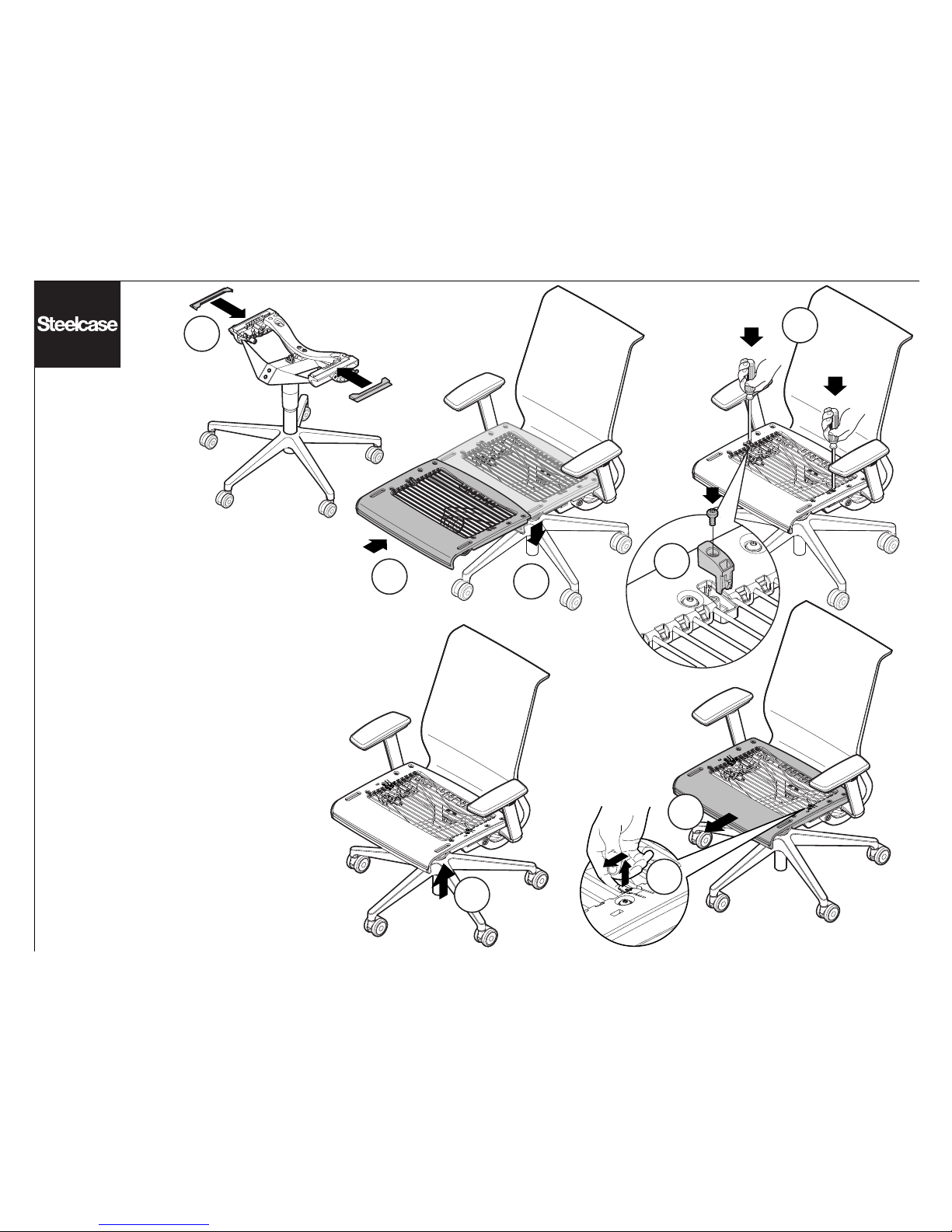
1a
1b
2b
1c
Page 11 of 19
939546506 Rev E
Installation & Removal
of the Seat Frame
NOTE: This operation can be done with or
without the upholstery installed.
Installation:
1. Install black slides onto mechanism (1a).
Lift up on seat slide lever, slide seat frame onto
side rails (1b) and lower seat slide lever (1c).
For chairs manufactured after October 2008,
the clips have snapped into position and the
installation is complete.
For chairs manufactured before October 2008:
2. Insert screw and seat slide stop block
(colored in apperance) on seat frame (2a)
(note position of stop block) with a torx T20
screwdriver (or Allen wrench) (2b). Repeat for
opposite side.
Removal:
Reverse to remove for chairs manufactured
before October 2008.
For chairs manufactured after October 2008:
3. Lift the seat bail.
4. Lift up on the release clip and slide the
side forward as far as it will go (4a). Repeat on
the other side and remove the seat (4b).
MANUFACTURED
AFTER OCTOBER 2008
2a
4b
4a
3
Page 12
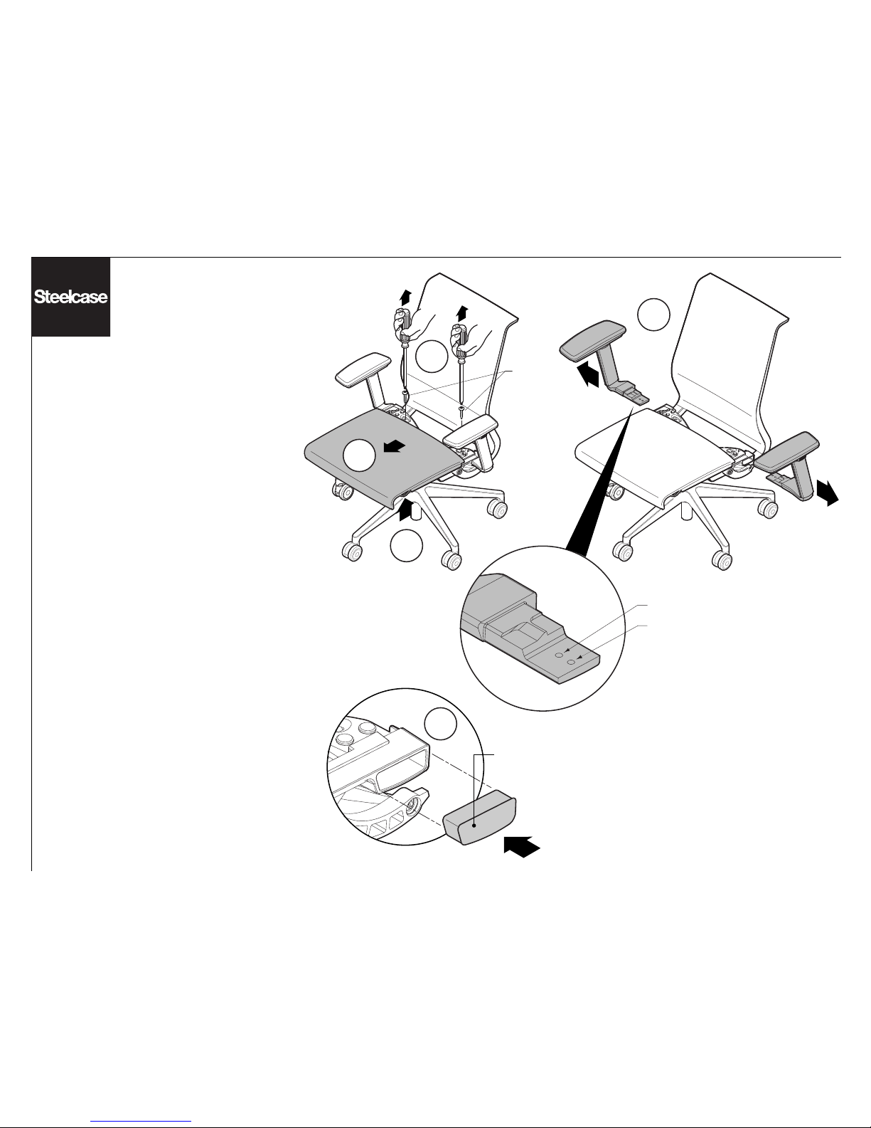
Wide Position
Narrow Position
Arm
Attachment
Screws
3
2a
2c
2b
A
Page 12 of 19
939546506 Rev E
Removal & Installation of the Arms
Prior to October 3, 2005
Removal:
1. See page 11 for removal of the seat slide stop
blocks.
2. Lift the seat slide lever (2a) and slide the seat
frame forward (as shown on page 8) until you can
see the arm attachment screws (2b). Remove arm
attachment screws with a torx T30 or #3 phillips
screwdriver (or Allen wrench) (2c).
3. Slide the arms out. Note which hole the arm
screw was in. (Arms are shipped in the wide
position).
Installation:
Slide the new arm in and align the correct position
hole. Tighten until fully seated using a torx T30
screwdriver (or Allen wrench). Repeat for the
opposite side. Slide the seat frame back and
re-install both seat slide stop blocks and the T20
torx screws as shown on page 8. Make sure not to
strip the screws (hand tighten).
A. When arms are not in use, a plug may be
inserted as a decorative effect (lightly tap).
DECORATIVE
PLUG
Page 13
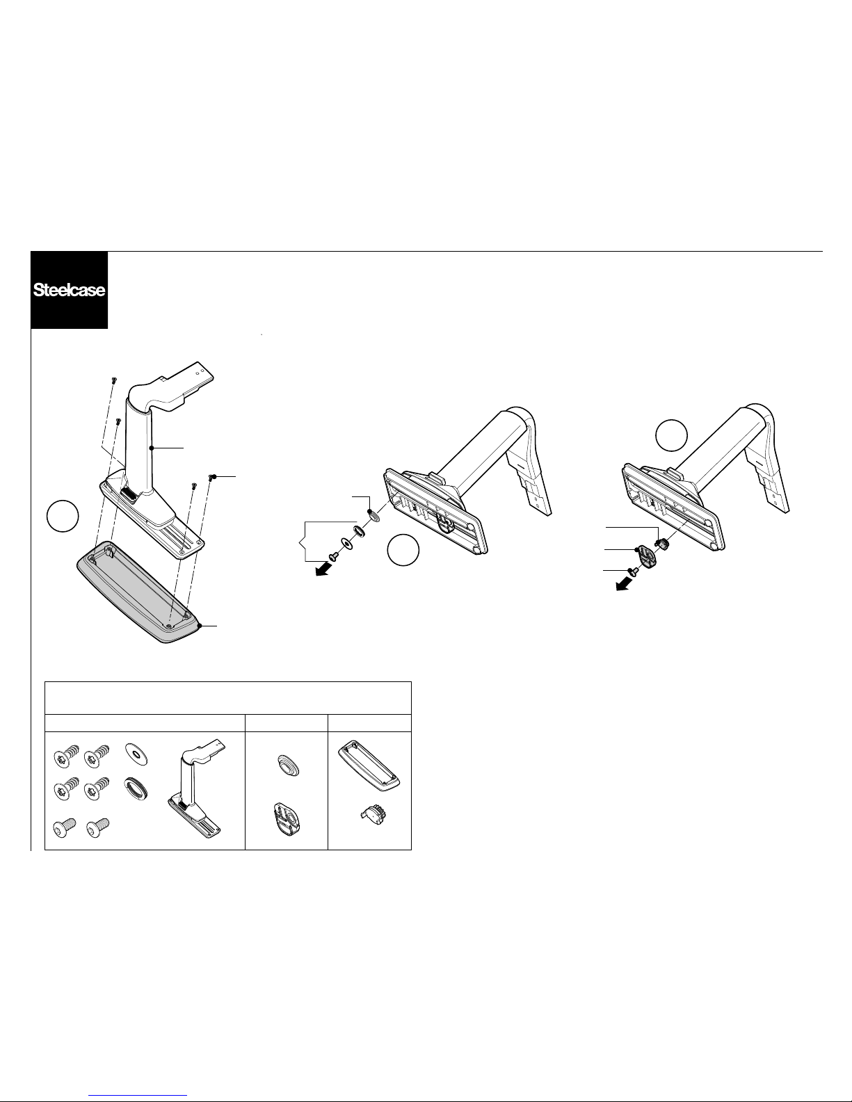
4
5
6
SCRAP
STEEL
ACETAL
STEEL
STEEL
STEEL
ACETAL
SCRAP
Bin for Components Removed
Steel ScrapAcetal
Page 13 of 19
939546506 Rev E
Page 14
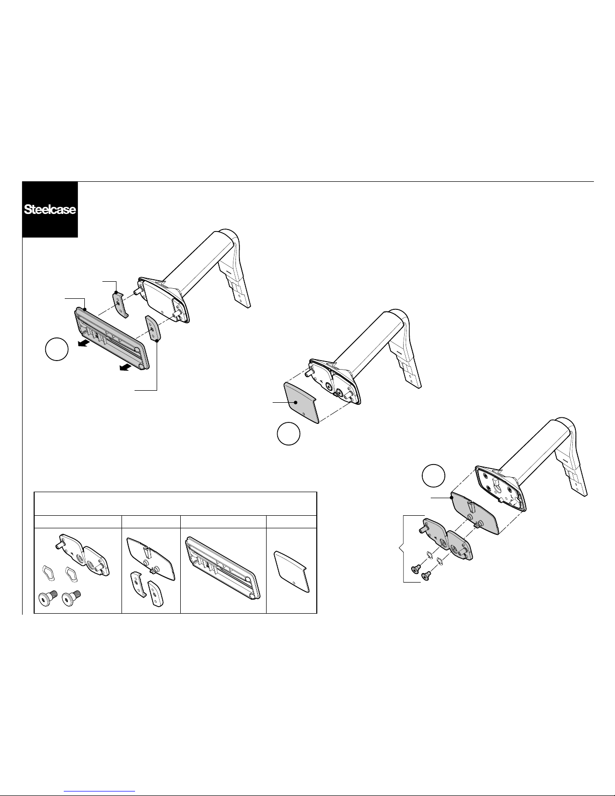
7
8
9
ACETAL
ABS
ACETAL
NYLON
ACETAL
STEEL
Bin for Components Removed
Steel ABSNylonAcetal
Page 14 of 19
939546506 Rev E
Page 15
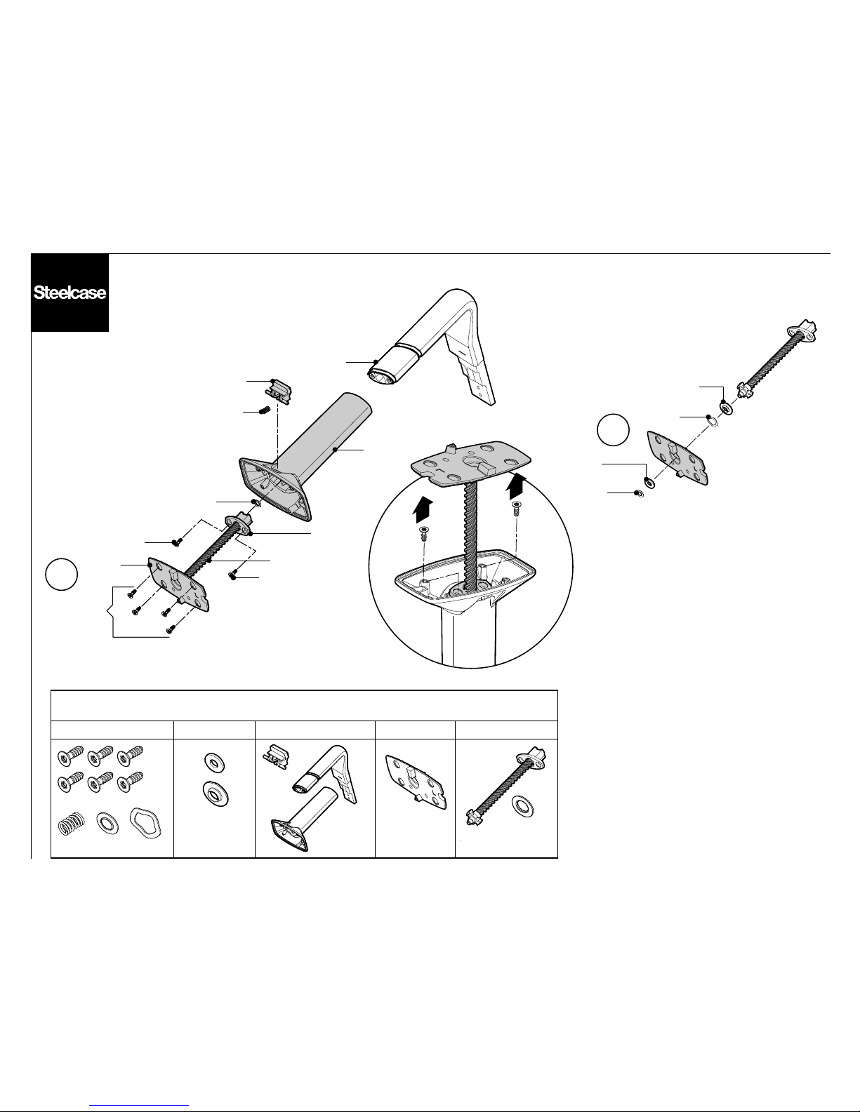
Bin for Components Removed
Steel ZINC SCRAPNylonAcetal
11
STEEL
STEEL
ACETAL
10
ZINC
STEEL
NYLON
STEEL
SCRAP
SCRAP
SCRAP
STEEL
NYLON
STEEL
NYLON
Page 15 of 19
939546506 Rev E
ACETAL
Page 16
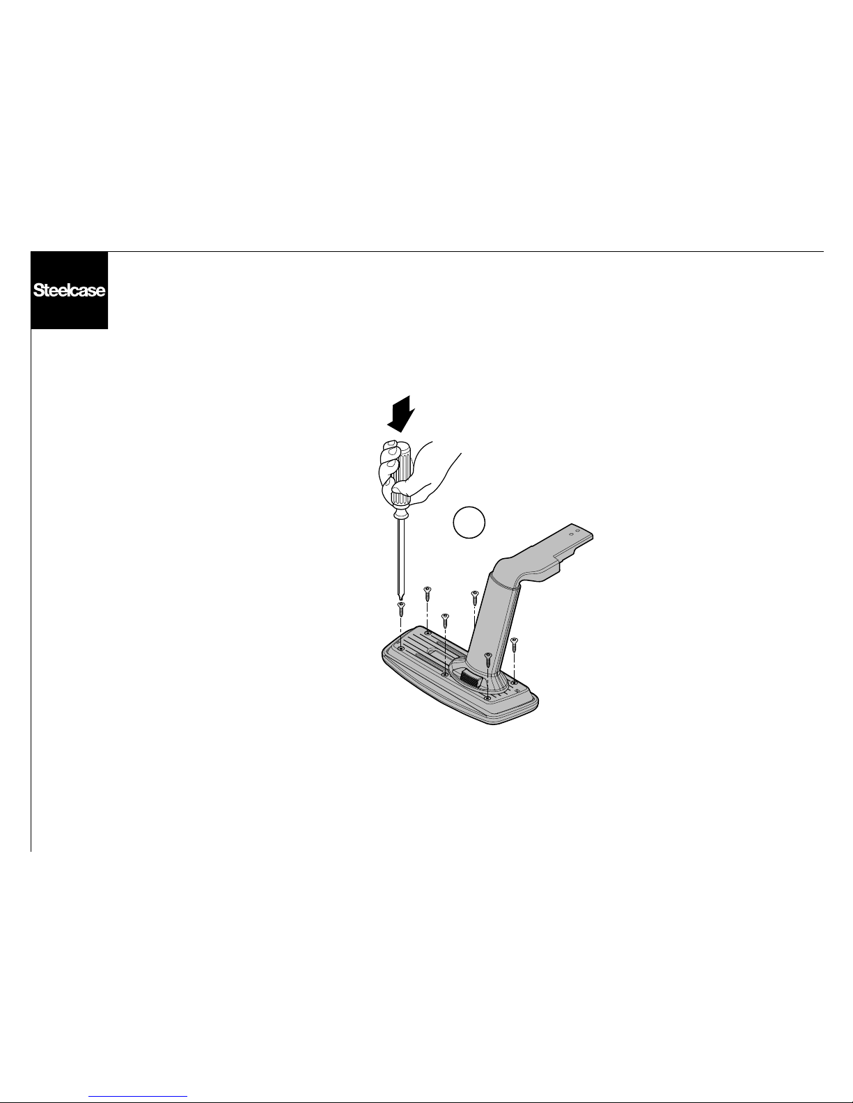
1
Page 16 of 19
939546506 Rev E
Replacement of the Arm Cap
1. Install six (6) screws, with a torx T20
screwdriver (or Allen wrench), to secure
the arm cap.
Reverse to remove.
Page 17
2 3
5
Page 17 of 19
939546506 Rev E
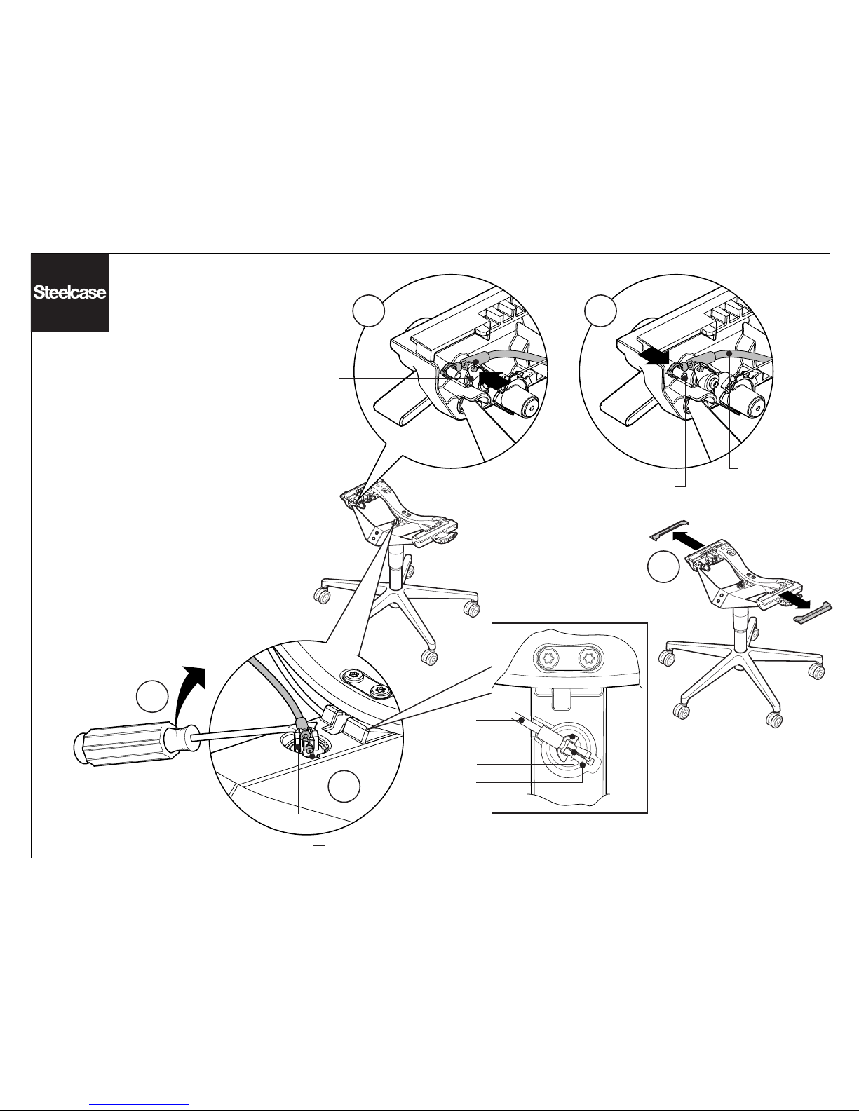
Removal & Installation
of the Mechanism
1. See page 11 for removal of seat, page 10 for removal
of back frame and page 12 for removal of arms.
2. Snap cable attachment clip out of the swing cam
bracket by pushing outward on cable attachment clip.
3. Remove cable from attachment post.
4. Pry other end of cable up from attachment bracket
with a flat bladed screwdriver (4a) and remove cable
from pneumatic cylinder adjustment bracket (4b).
5. Remove black slides from mechanism.
6. See page 19 for removal of cylinder from chair
control mechanism.
Reverse to install.
SWING CAM
BRACKET
CABLE
ATTACHMENT CLIP
ATTACHMENT POST
CABLE
4a
4b
PNEUMATIC CYLINDER
ADJUSTMENT BRACKET
ATTACHMENT
BRACKET
PNEUMATIC
CYLINDER
ADJUSTMENT
BRACKET
Top View of Cylinder
On installation, align cylinder with
center of chair control as shown
before seating on cylinder.
CABLE
ATTACHMENT
BRACKET
CABLE
Page 18
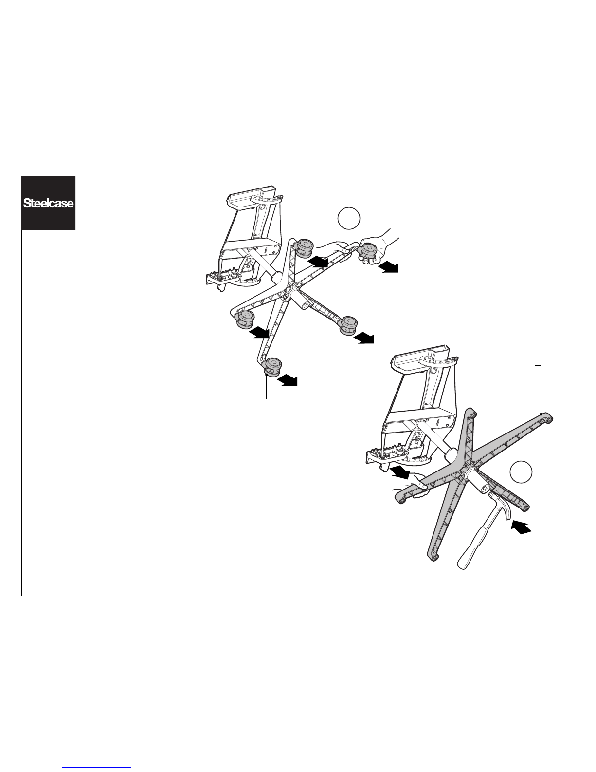
BASE
CASTER
1
2
Page 18 of 19
939546506 Rev E
Removal of the Base
1. Use hands to pull all five (5) casters
from the base.
2. Use a hammer to remove the base
from the cylinder by pushing with hand
downward on base and hitting the
bottom of the cylinder with a hammer.
Installation of the base
Snap casters onto base by hand then
place cylinder into base and sit in chair
to seat cylinder on base.
Page 19
1b
1a
Page 19 of 19
939546506 Rev E
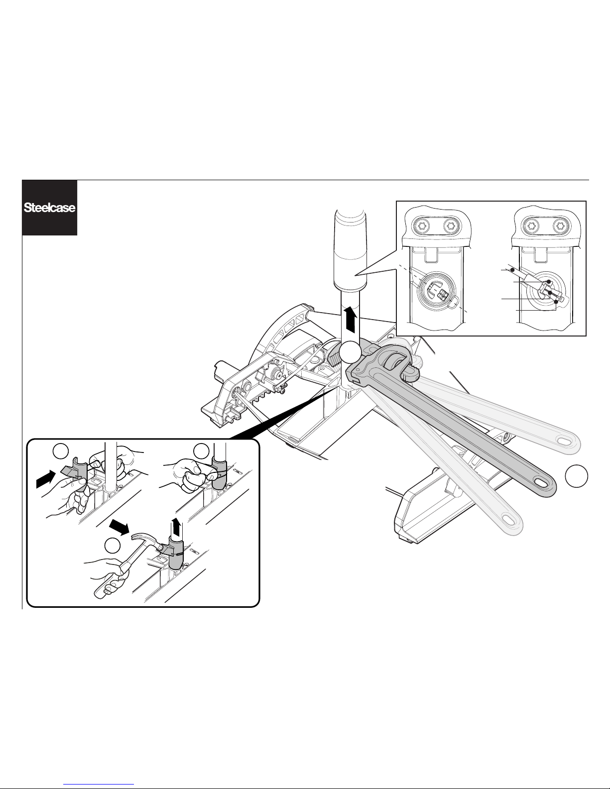
Removal & Installation
of the Cylinder
If the chair control is operational but the
pneumatic cylinder isn't then use this method:
1. Place pipe wrench as close to chair control
as possible and twist cylinder back and forth
(1a) while lifting on the cylinder (1b).
Reminder: The pipe wrench will render the
cylinder inoperable.
If pneumatic cylinder does not separate from
the chair control, apply WD-40 where cylinder
is embedded into the chair control. Wait
approx. 20 minutes and repeat.
2a 2b
2c
On installation, align cylinder with
center of chair control as shown
before seating on cylinder.
PNEUMATIC
CYLINDER
ADJUSTMENT
BRACKET
Top View of Cylinder
CABLE
ATTACHMENT
BRACKET
CABLE
If the pneumatic cylinder is
operational but the chair control
isn't then use this method:
2. Install the pneumatic cylinder
removal tool (part number
879100100) on the top part of the
lift, as close as possible to the
control (2a & 2b). Apply lifting force
to the cylinder, with one hand. With
the hammer in the other hand, give
the removal tool several solid hits,
on the flat part (2c).
Reminder: The removal tool will
render the chair contol inoperable.
 Loading...