

Page 1
®
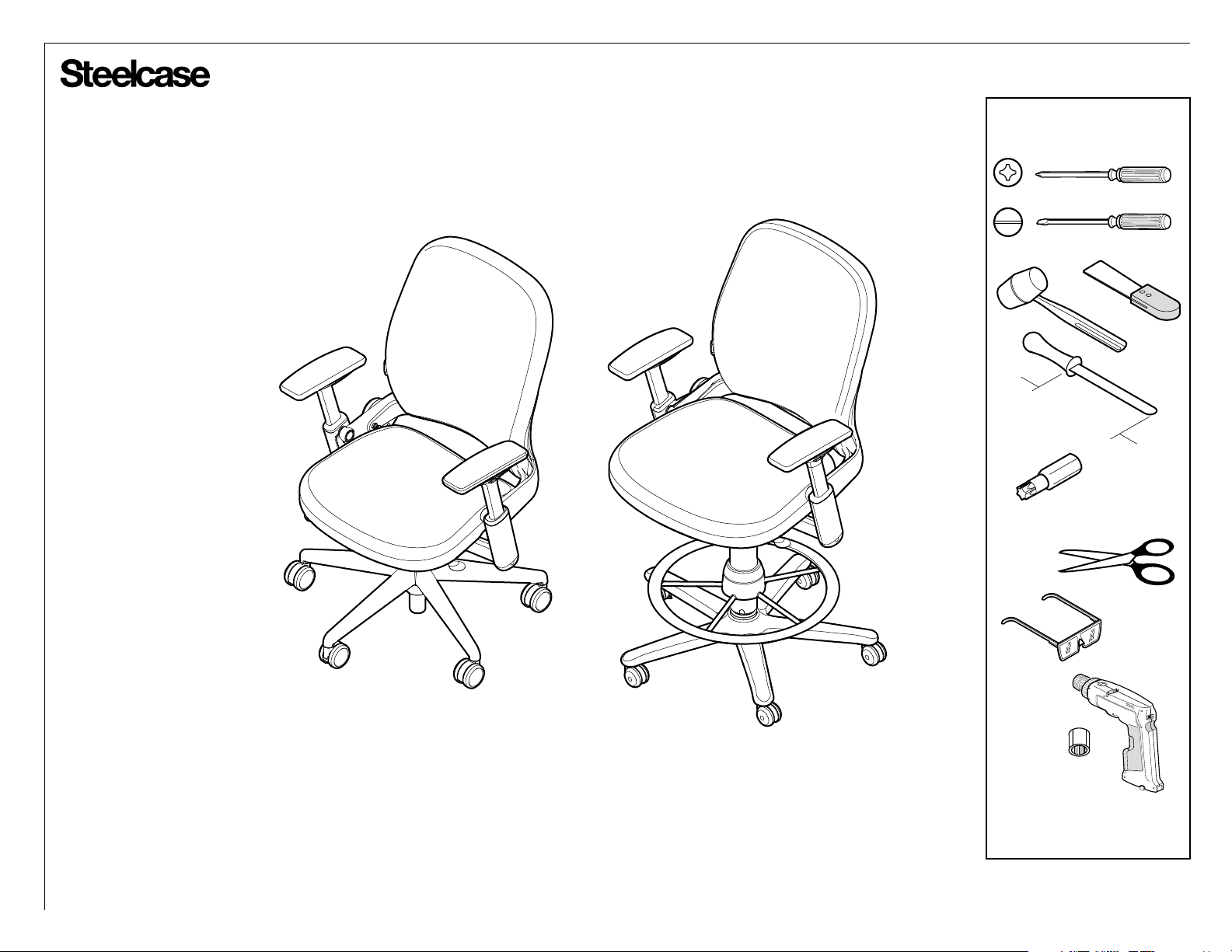
462 Leap® Task Chair and Stool Disassembly
8" minimum
T-20, T-25, T-30
If you have a problem, question, or request, call
your local dealer, or Steelcase Line 1 at
888.STEELCASE (888.783.3522)
for immediate action by people who want to help you.
(Outside the U.S.A., Canada, Mexico, Puerto Rico,
and the U.S. Virgin Islands, call: 1.616.247.2500)
Or visit our website: www.steelcase.com
©
2010 Steelcase Inc.
Grand Rapids, MI 49501
U.S.A.
Printed in U.S.A.
1/2"
Page 1 of 20
939546225 Rev A
Page 2
®
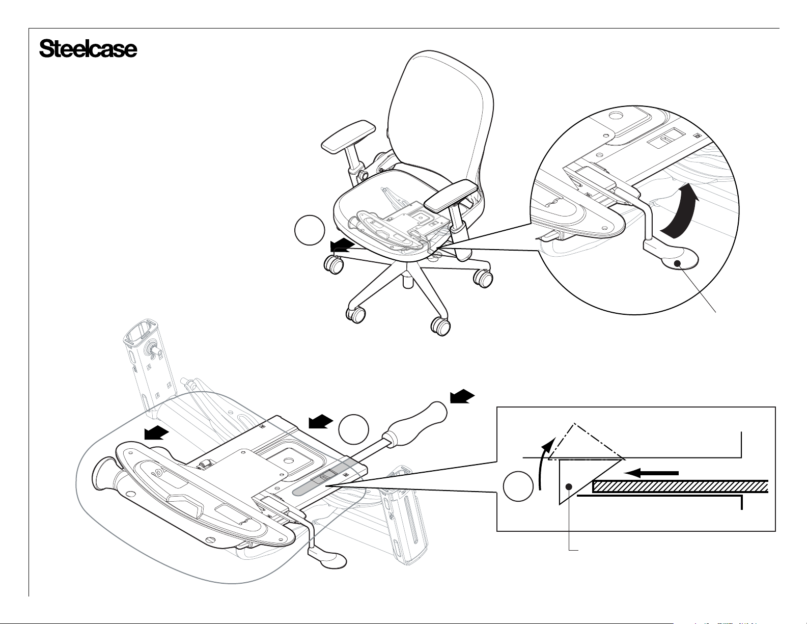
Seat Disassembly
1. Slide seat fully forward while holding the
seat slide lever.
2. Locate the white quick release tab located
on the left hand side of the chair (as you sit in
it) between the plates.
3. Lift the quick release tab while pulling the
seat slide lever and sliding the seat forward.
1
SEAT SLIDE
LEVER
FRONT
REAR
FRONT REAR
2
3
QUICK RELEASE TAB
Page 2 of 20
939546225 Rev A
Page 3
®
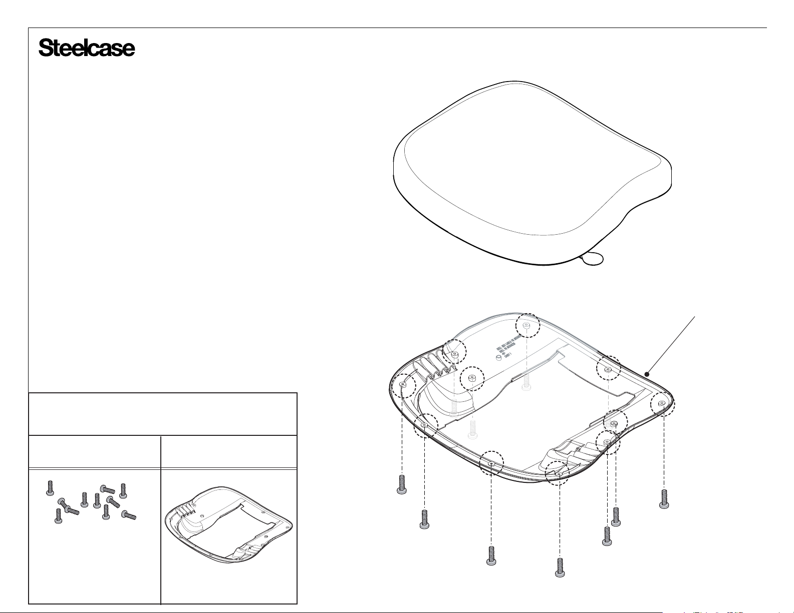
4. Remove 11 screws from bottom of
outer seat shell.
SEAT SHELL
Bins for components
removed
PolypropyleneSteel
Page 3 of 20
939546225 Rev A
Page 4

®
5. Remove two (2) screws 'A'
which fasten panel cover and top
plate. Remove panel cover.
6. Remove top plate, grommet and
two (2) depth bearings
7. Remove leaf spring and two (2)
front slide pads.
8. Remove seat depth lever and handle,
hinge adjustment plate and seat depth
spring.
FRONT SLIDE
PAD (2)
LEAF
SPRING
DEPTH
SPRING
9. Remove two (2) screws 'B' which
fasten the support plate.
Bins for components
removed
Steel Nylon Scrap
Acetal
Polyethylene
LEVER
HINGE
GROMMET
OUTER DEPTH
BEARING (2)
5
PANEL
COVER
SCREW 'A'
SUPPORT
PLATE
SCREW 'B'
TOP
PLATE
9
Page 4 of 20
939546225 Rev A
Page 5
®
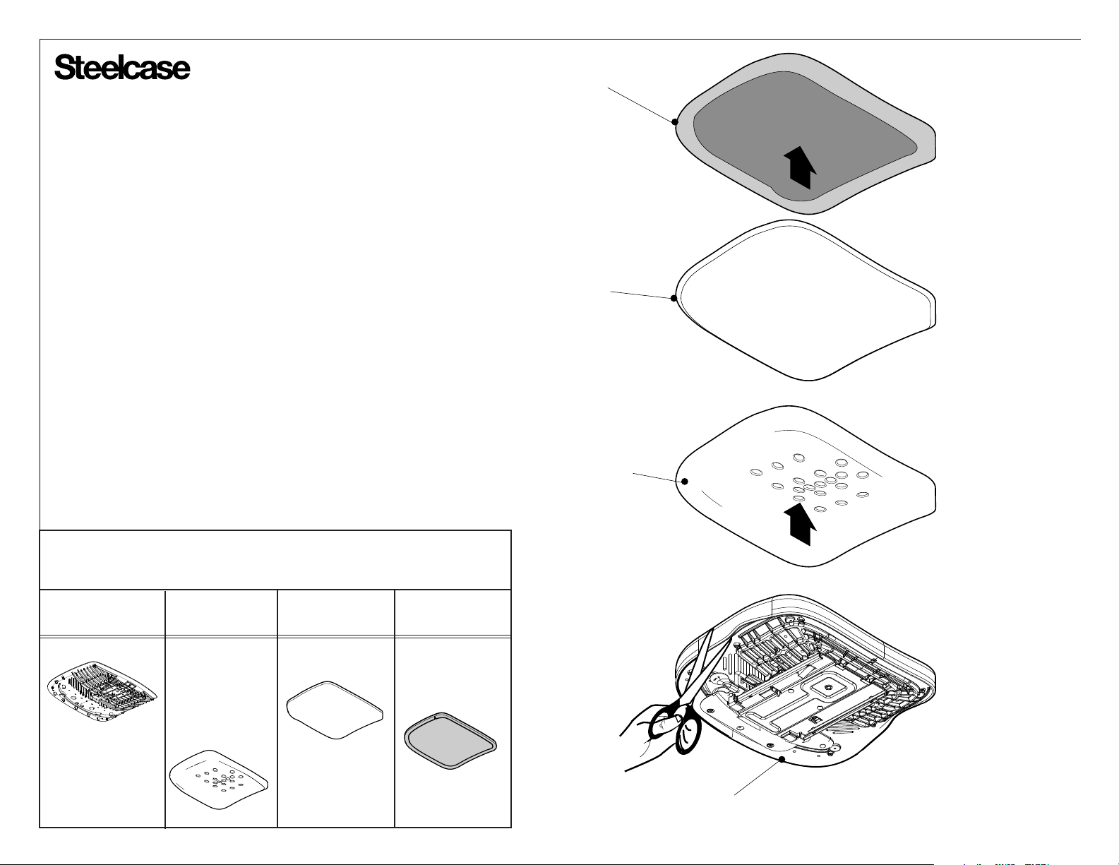
10. Cut the fabric drawstring around the inner
shell. Lift fabric covered cushion and separate
fabric, topper fiber and cushion. Recycle
materials as shown.
FABRIC
FIBER
TOPPER
Polypropylene
Bins for components
removed
Antimony Free
Polyester
CUSHION
FabricPolyurethane
INNER
SHELL
Page 5 of 20
939546225 Rev A
Page 6
®
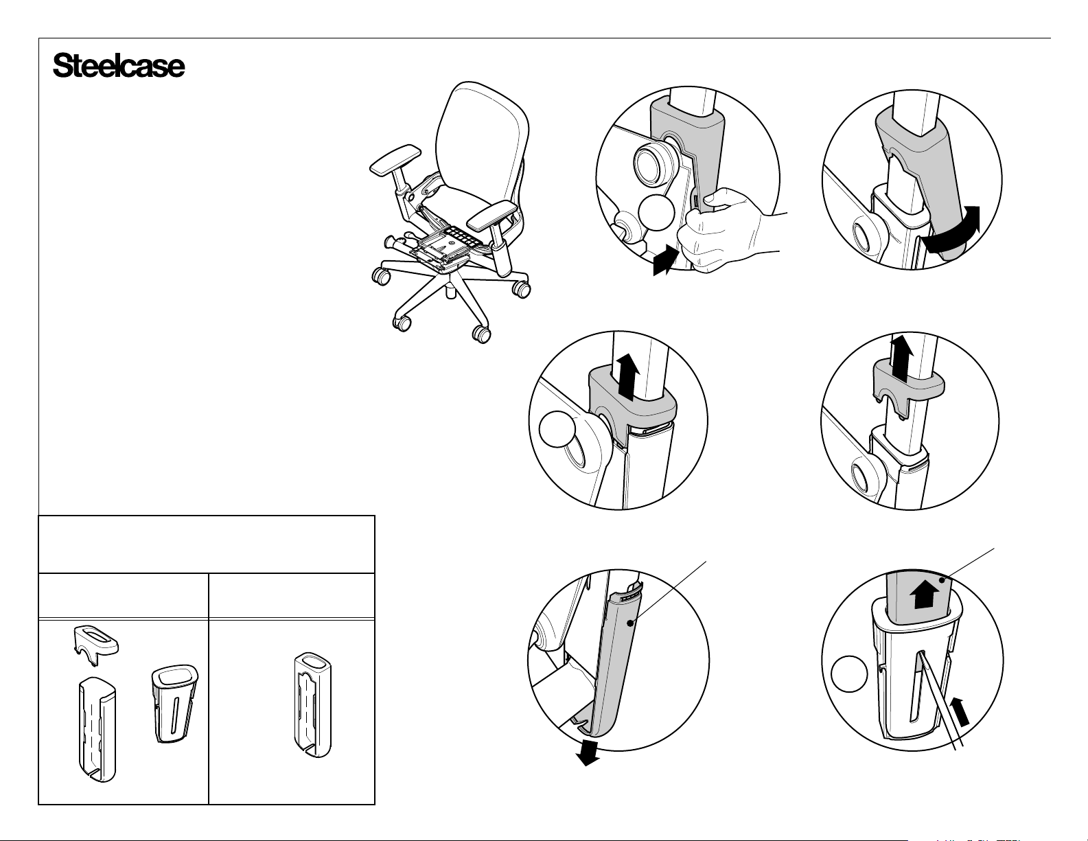
Arm Disassembly
1. With the arm adjusted all the way up,
remove the outer pod cover and arm by one
of the following methods:
a) For black and midnight colored chairs, pull
the pod cover out from the bottom thus
releasing it from the inside cover and clearing
the steel bracket. Slide the cover up until it is
loose around the arm stalk. Skip to step C for
arm removal.
Black and Midnight
1a
b) For platinum colored chairs, gently pry the
pod cap off the pod cover and slide it up the
arm stalk. Push the pod cover halfway down
and follow step C for arm removal.
c) While holding trigger button, use a flat head
screwdriver to deflect snap and gently remove
arm and cover from arm insert.
Bins for components
removed
Nylon
(platinum)
Polypropylene
(black and midnight)
1b
Platinum
POD
COVER
ARM
1c
Page 6 of 20
939546225 Rev A
Page 7
®
MOLDED FOAM
ASSEMBLY
3
ARM CAP SKIN
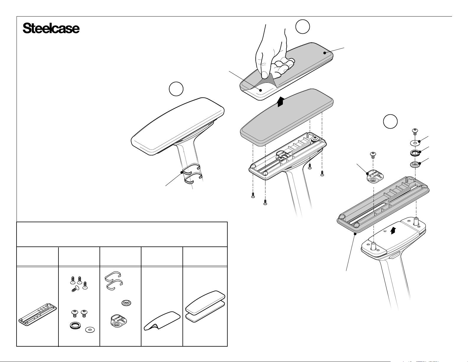
2. Remove two (2) height adjustment
bearings.
3. Use a T-20 bit to remove four (4)
screws under arm cap. Lift and remove
outer arm cap. Pull arm cap skin off arm
cap. Scrap remaining molded foam
assembly.
4. Use a T-20 drive bit to remove
two(2) screws and pull off lower
arm cap support, rear bearing, front
bracket, spring and washer.
Bins for components
removed
Nylon
Steel ScrapUrethane
Acetal
HEIGHT ADJUSTMENT
BEARING
2
4
WASHER
SPRING
FRONT
BRACKET
REAR
BEARING
LOWER ARM
CAP SUPPORT
Page 7 of 20
939546225 Rev A
Page 8
®
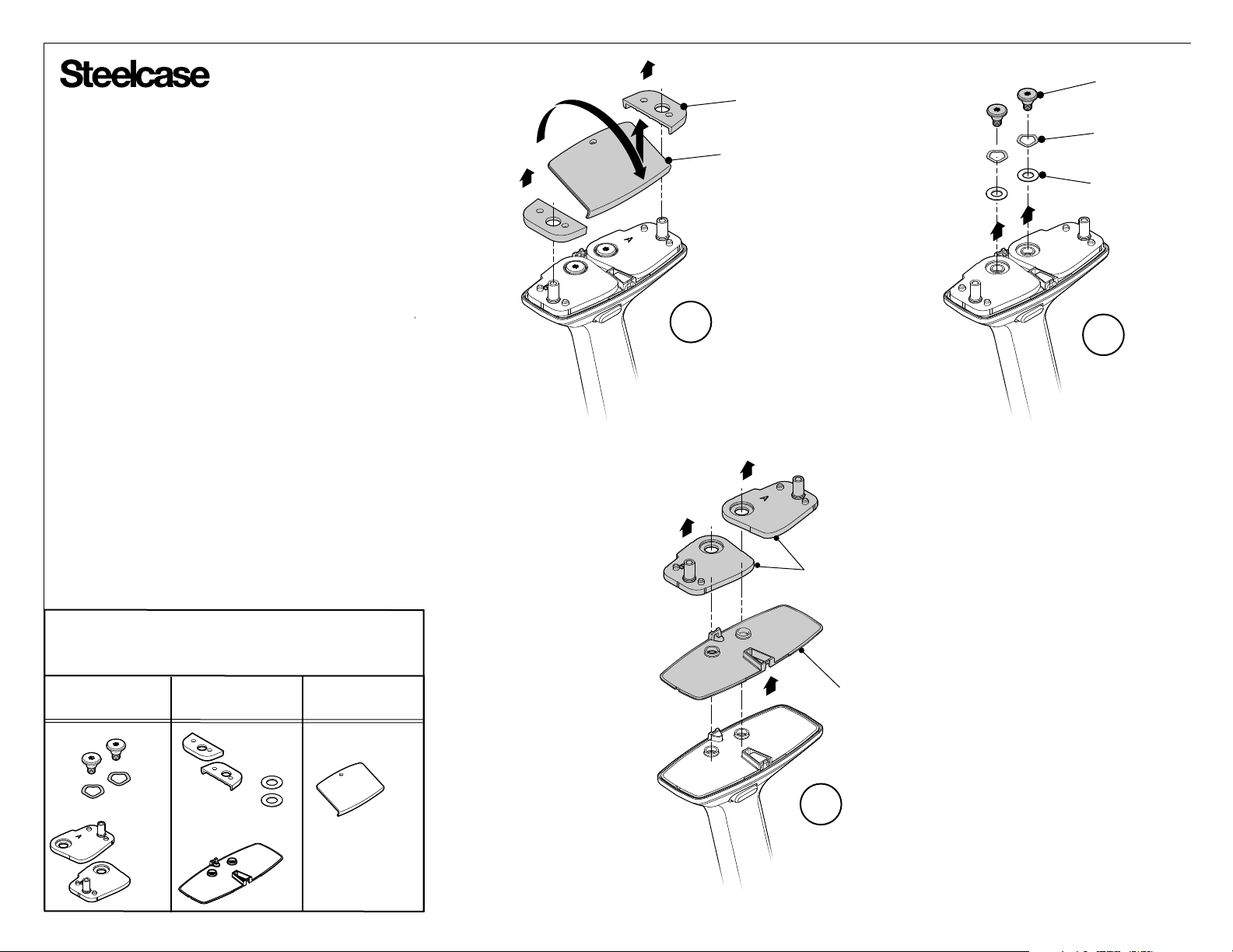
5. Remove flat pivot cover and the two (2) swing arm
bearings as shown.
6. Use a T-25 drive bit to remove the two (2) shoulder
screws. Remove two (2) wave washers and two (2)
acetal washers.
7. Remove two (2) swing arm links and pivot plate
as shown.
5
SWING ARM
BEARING
FLAT PIVOT
COVER
SHOULDER
SCREW
WAVE
WASHER
ACETAL
WASHER
6
Bins for components
removed
Steel ABSAcetal
SWING ARM
LINKS
PIVOT
PLATE
7
Page 8 of 20
939546225 Rev A
Page 9
®
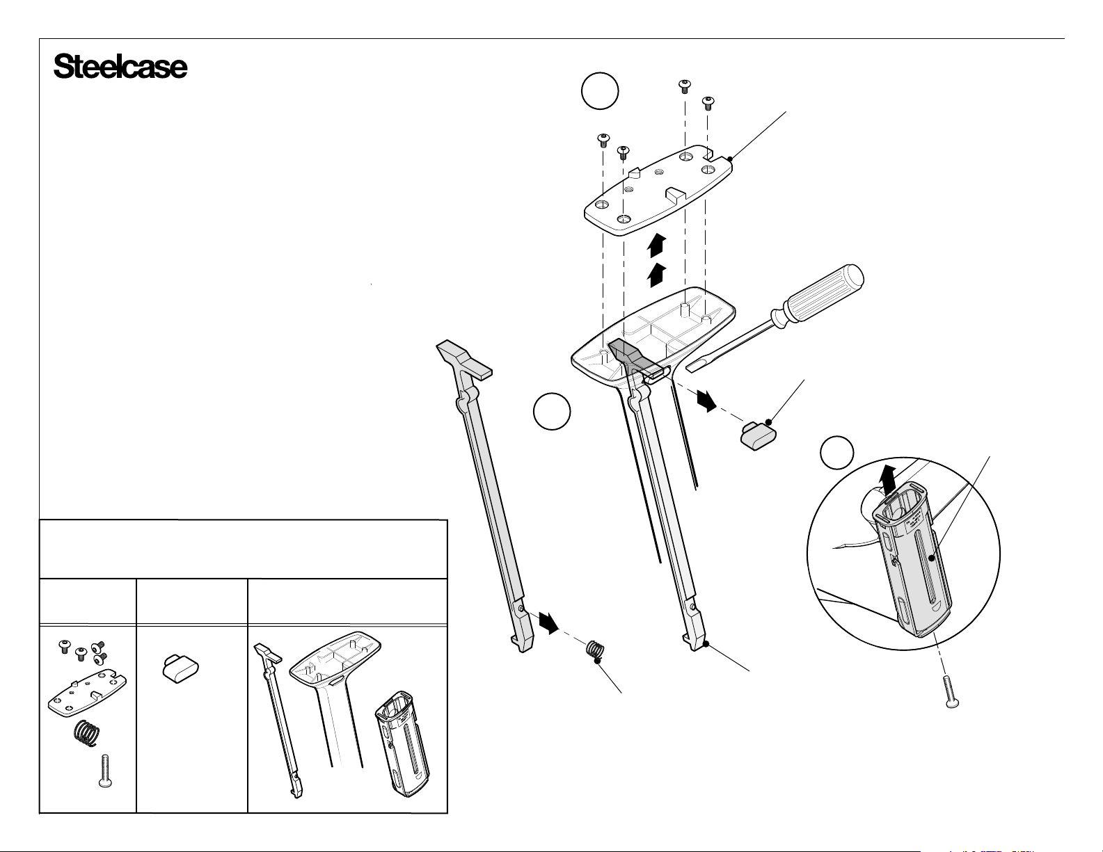
8. Use T-20 drive bit to remove four (4) screws and pull off pivot
arm mounting base plate.
9. Pry the activator button off using a flat-bladed screwdriver. Lift
and remove height adjustment lever and height adjustment spring.
10. Remove screw on bottom of arm cap bracket.
Remove arm cap bracket.
NOTE: Repeat steps 1 through10 to disassemble arm
on opposite side.
8
PIVOT ARM MOUNTING
BASE PLATE
ACTIVATOR
BUTTON
9
ARM CAP
10
BRACKET
Bins for components
removed
Steel Polypropylene Nylon
SPRING
HEIGHT ADJUSTMENT
LEVER
Page 9 of 20
939546225 Rev A
Page 10
®
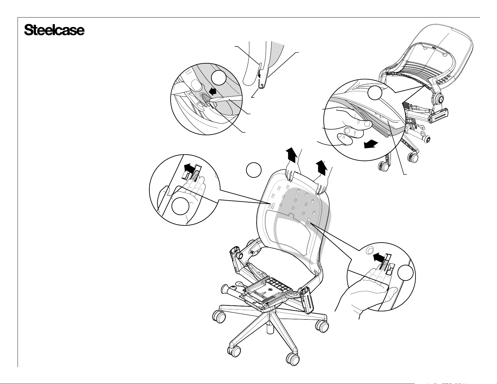
Back Disassembly
1. Remove the j-channel, located on
bottom of back, from the channel slot.
Use a flat-bladed screwdriver to begin
the removal process.
2. Position chair upright. Slide hand
between cushion and outer back shell
to disengage tabs on both sides.
3. Pull up & out on the cushion to
remove from the back shell.
BACK CHANNEL SLOT
1a
2
J-CHANNEL
FLAT-BLADED
SCREWDRIVER
J-CHANNEL
3
ELASTIC BAND ON BOTTOM
OF BACK CUSHION
1b
BACK CHANNEL SLOT
2
Page 10 of 20
939546225 Rev A
Page 11
®
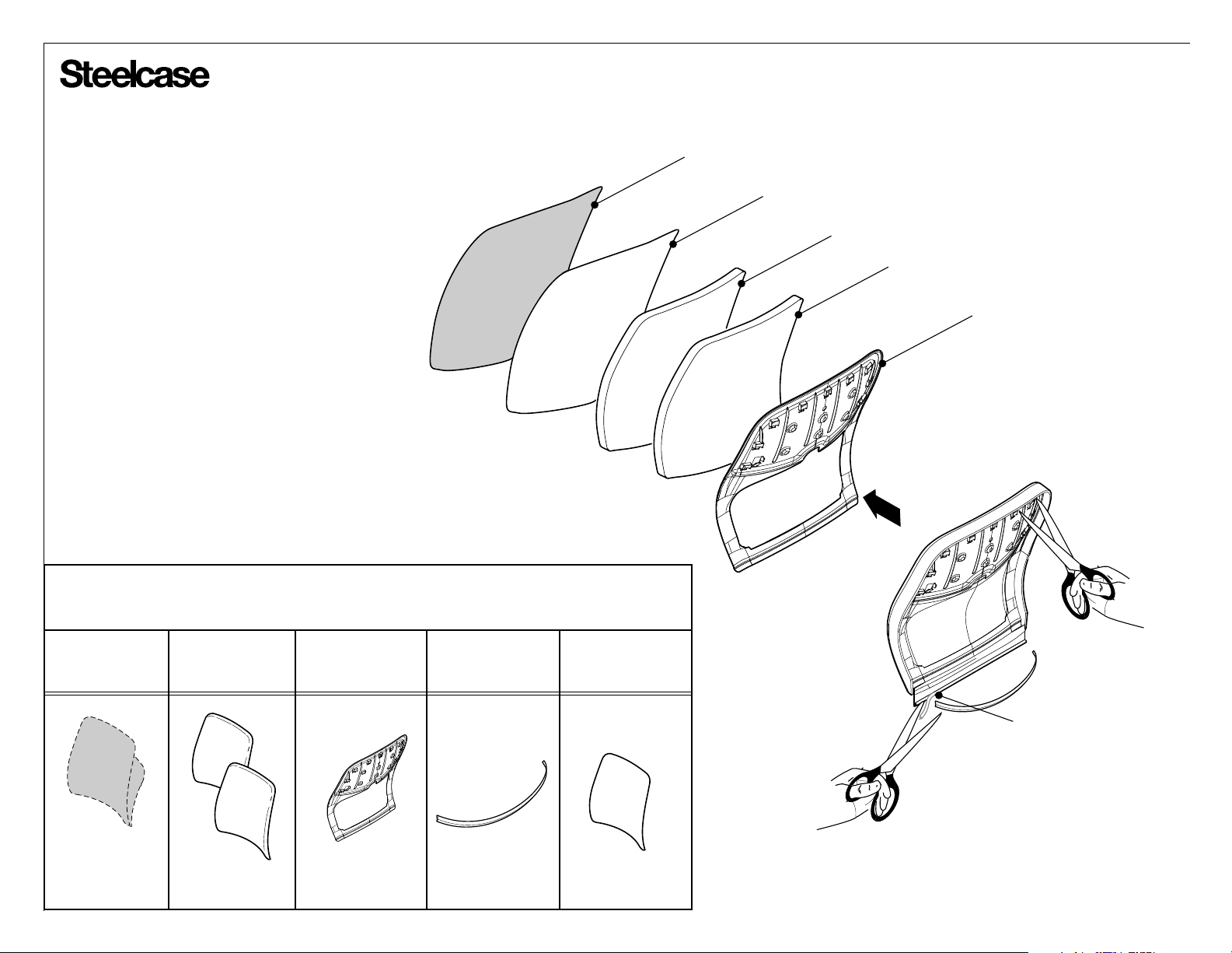
FABRIC
NYLON KIT
4. Cut drawstring and J-Channel off.
Place fabric, nylon kit, foam and inner
back shell in appropriate bin.
Bins for components
removed
Fabric Polyurethane
Foam
Polypropylene Polyethylene Nylon
FOAM
FOAM
INNER BACK SHELL
J-CHANNEL
Page 11 of 20
939546225 Rev A
Page 12
®®
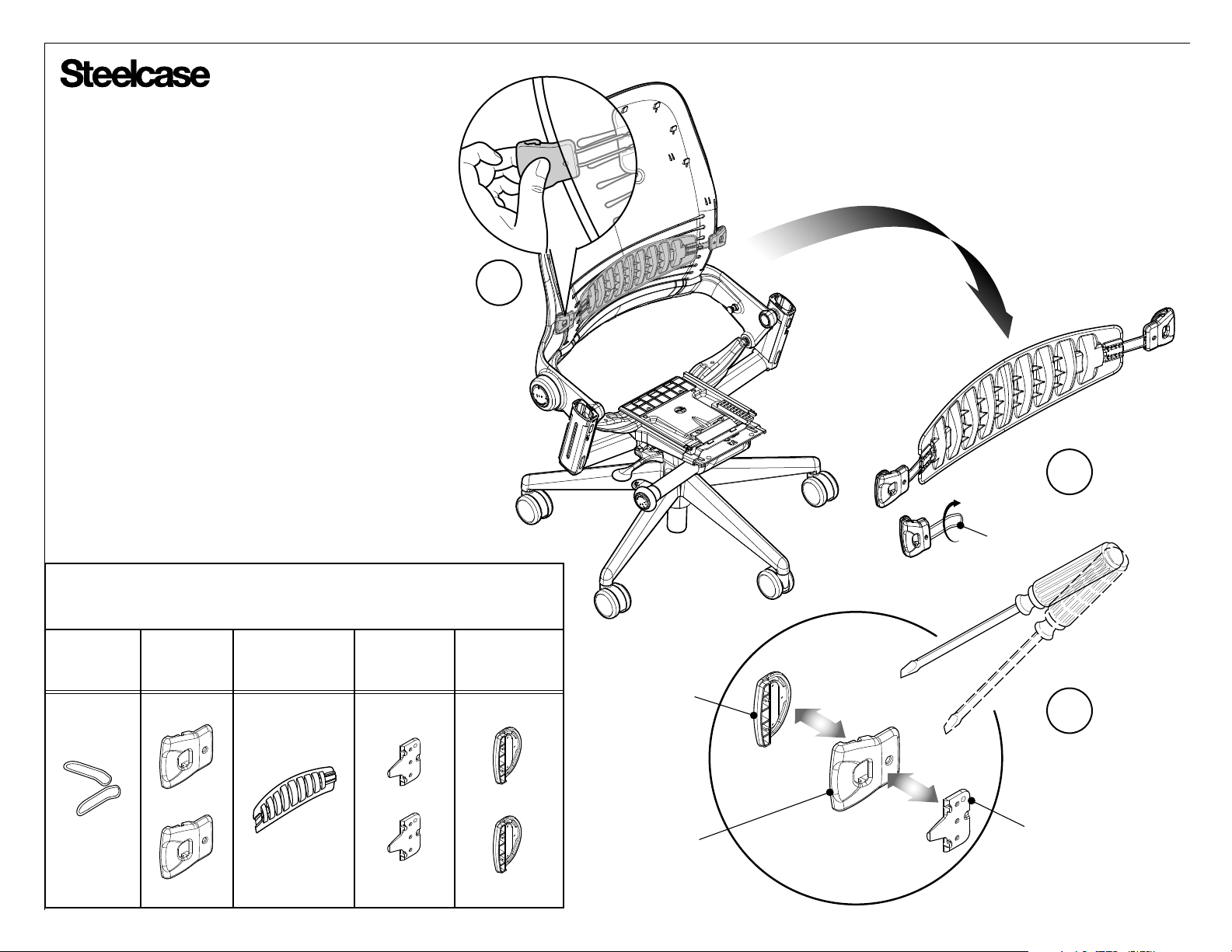
5. Remove lumbar assembly by pulling one tab
outward.
6. Remove lumbar tabs by pulling outward,
twisting, and snapping off handle spring from
lumbar back.
7. Insert flat-bladed screwdriver between front
and back lumbar handle and twist to break apart.
Insert flat-bladed screwdriver between lumbar
handle retainer and back lumbar handle then twist
to break apart. Repeat for each tab.
Bins for components
removed
Steel ScrapABS AcetalPolypropylene
5
6
HANDLE SPRING
FRONT LUMBAR
HANDLE
7
BACK LUMBAR
HANDLE
LUMBAR HANDLE
RETAINER
Page 12 of 20
939546225 Rev A
Page 13
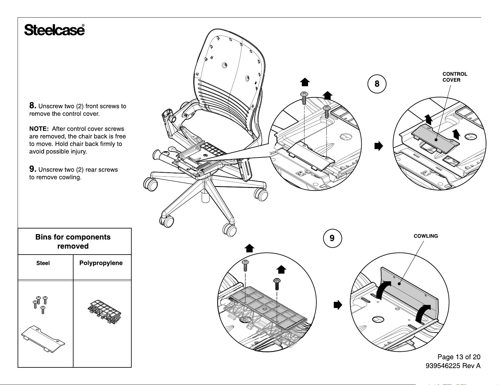
Page 14
®
2a
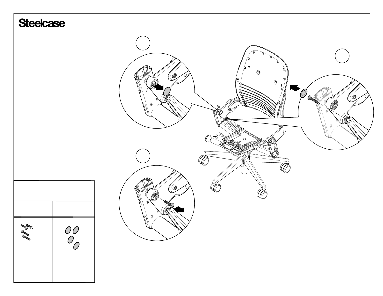
Back Disassembly
1. Position chair upright.
2. Pop screw covers out (2a) and remove
upper pivot screws (2b).
3. Pop screw covers out and remove
lower pivot screws.
Bins for components
removed
3
2b
Steel Polypropylene
Page 14 of 20
939546225 Rev A
Page 15
®
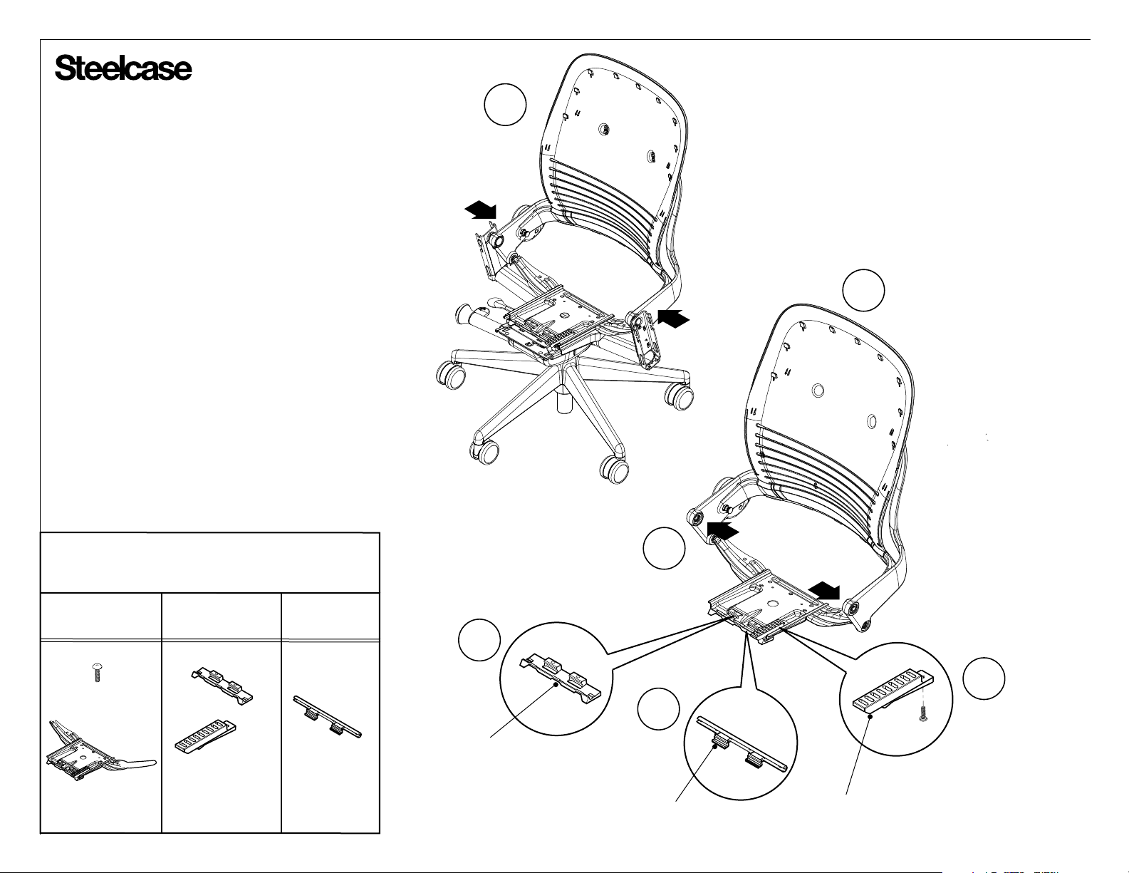
Back Disassembly
4. Compress back frame inward off arm rivets at points as
indicated.
5. Remove back frame and seat carrier from chair.
6. Remove inner and outer carrier bearings.
7. Unscrew depth adjustment block to remove.
8. Remove seat carrier assembly from back frame
assembly by pressing outward.
4
5
Bins for components
removed
Steel Nylon Acetal
6
INNER CARRIER
BEARING
8
6
OUTER CARRIER
BEARING
DEPTH ADJUSTMENT
BLOCK
7
Page 15 of 20
939546225 Rev A
Page 16
®
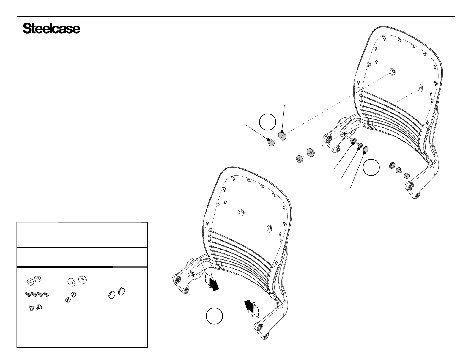
Back Disassembly
9. Pop screw covers off lower pivot screws, then remove screws
and pivot bearing.
10. Remove upper nuts and bearing using 1/2" socket wrench.
11. Compress back shell frame inward to remove from ribbon
assembly.
UPPER NUT
UPPER BEARING
10
Bins for components
removed
Steel Acetal Polypropylene
11
PIVOT BEARING
SCREW
9
COVER
Page 16 of 20
939546225 Rev A
Page 17
®
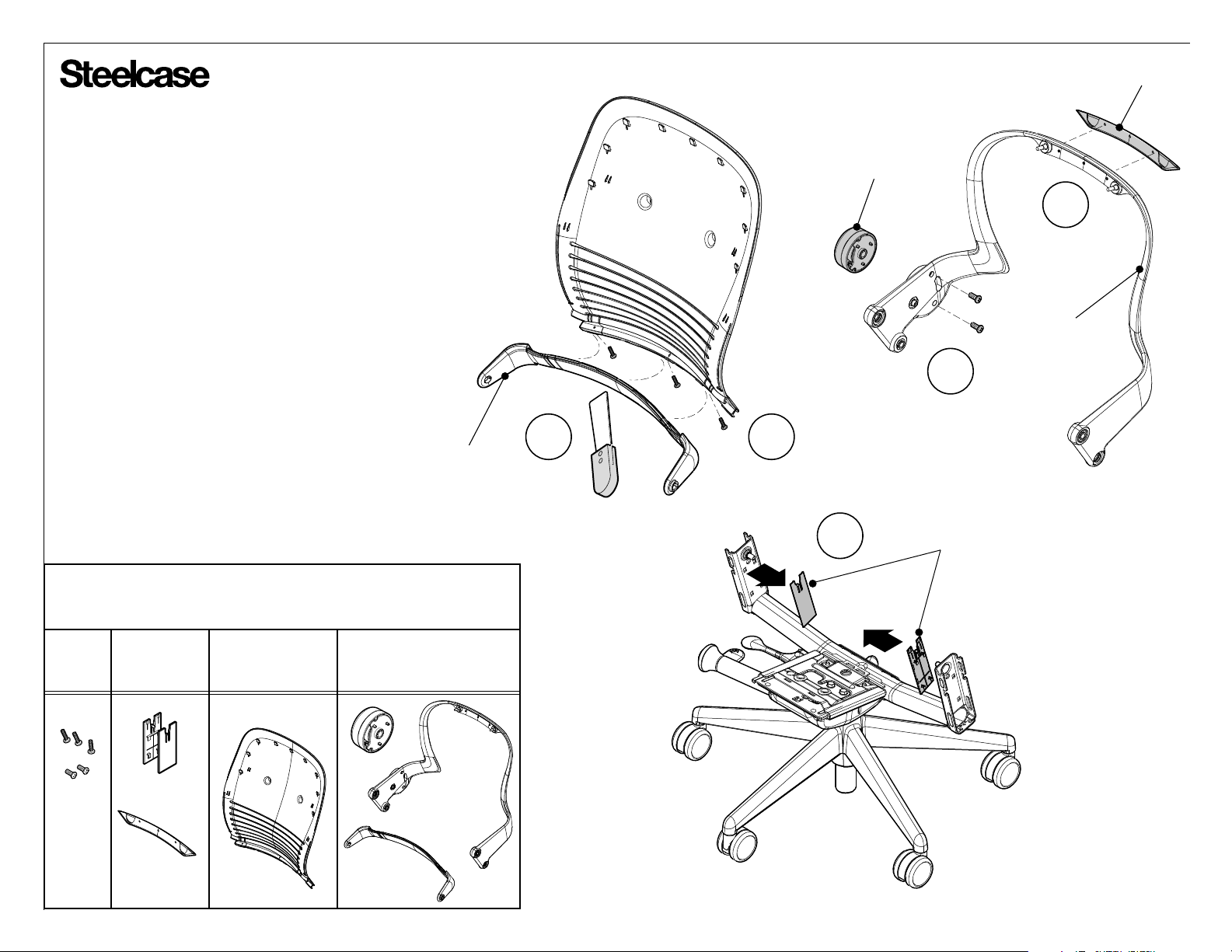
12. Remove 3 screws from under belt assembly
13. Remove belt assembly by prying along edge
with 2" putty knife.
14. Remove two, (2), screws to disengage lumbar
resistance assembly.
NAME PLATE
LUMBAR RESISTANCE
ASSEMBLY
15
BACK RIBBON
15. Pry name plate from back ribbon using
flat-bladed screwdriver.
16. Remove inner arm covers.
Bins for components
removed
Steel ABS ScrapPolypropylene
BELT ASSEMBLY
13
12
16
14
INNER ARM COVER
Page 17 of 20
939546225 Rev A
Page 18
®
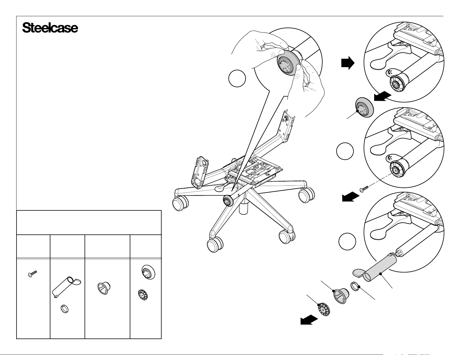
Chair Control Disassembly
1. Peel cap from upper back force
control knob.
2. Turning clockwise, remove the LEFT
HANDED screw from clutch puck.
3. Remove bell assembly, lever bushing,
and variable backstop lever and cap.
Bins for components
removed
Steel Nylon ScrapPolypropylene
1
CAP
2
3
BACKSTOP CAP
BELL ASSEMBLY
BACKSTOP LEVER
LEVER BUSHING
Page 18 of 20
939546225 Rev A
Page 19
®
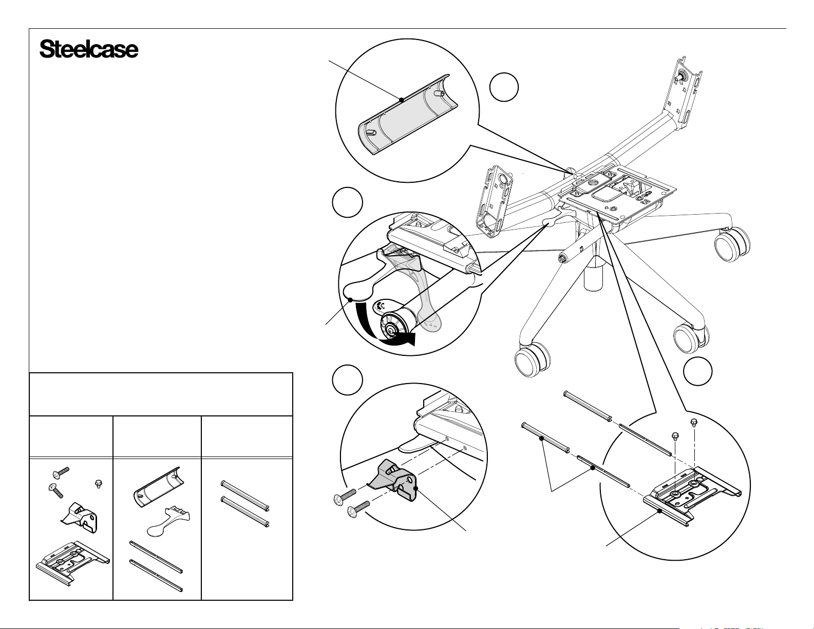
ARM TUBE COVER
4. Push down on handle until it breaks loose from
the bracket.
5. Loosen fasteners and remove bracket.
6
6. Remove arm tube cover from arm tube
assembly.
7. Remove bolts using a 1/2" socket wrench.
8. Pull carrier seat plate and carrier bearings from
front of control mechanism assembly.
Bins for components
removed
Steel Nylon Acetal
4
HANDLE
7
5
CARRIER BEARINGS
BRACKET
CARRIER
SEAT PLATE
Page 19 of 20
939546225 Rev A
Page 20
®
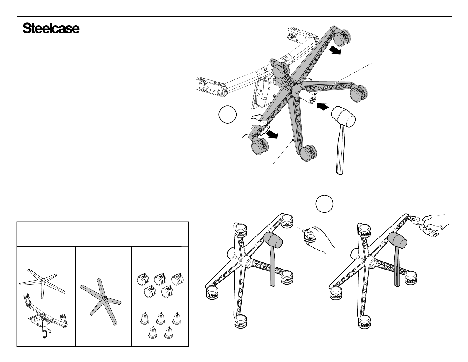
Base Disassembly
1. Adjust chair to maximum height (if possible)
and position as shown. Hit bottom of the cylinder
with a hammer (or mallet) while pulling forward on
the chair base to remove base. Recycle control
and cylinder assembly.
NOTE: If stool chair, loosen and remove footring.
2. Tap base with a mallet while pulling on the
caster to remove each caster. If caster pulls off
without the stem, use pliers to remove stem.
Recycle as shown below.
CYLINDER
1
BASE
Steel
2
Bins for components
removed
Nylon Scrap
OR
Page 20 of 20
939546225 Rev A
 Loading...