

Steelcase 3 Series Troubleshooting Manual
Troubleshooting Guide
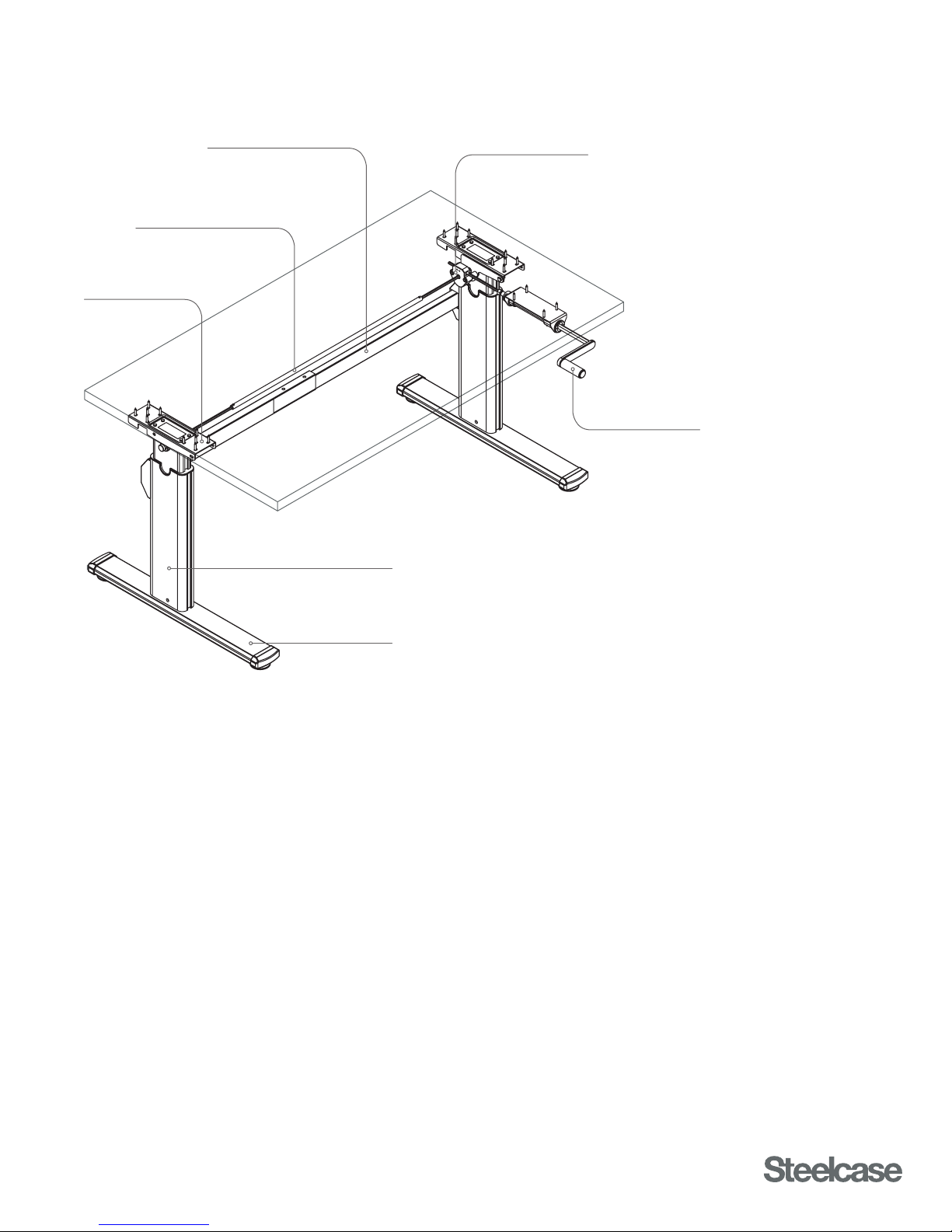
Driveshaft
Top Mounting Plate
Stretcher
Gearbox
Crank Handle
Lifting Column
Foot
SERIES 3 TABLES
HOW THEY WORK
• Each Lifting Column contains a mechanical lift mechanism that requires an external force to operate.
• Lifting Columns and Gearboxes are connected to and mechanically synchronized with each other
through a telescoping Driveshaft assembly.
• A hand-operated crank provides torque to operate the Lifting Columns.
• Each Lifting Column contains internal stops that define the top and bottom of the range of motion.
• Only one Crank Handle is used to drive the Lifting Columns, regardless of whether the Table has
two or three Lifting Columns.
• The Crank Handle raises and lowers 2-leg Tables through a 4:1 ratio Gearbox.
• The Crank Handle raises and lowers 3-leg (90º Corner) Tables through a 6:1 ratio Gearbox.
• Certain small Tables have a Top-Crank Handle configuration; all other sizes have a Front-Crank Handle.
Refer to the Spec Guide for more information.
Published 4/2016

READ THE ASSEMBLY DIRECTIONS AND USER GUIDE
Many times, problems can be the result of improper assembly. Reference the Assembly Directions
document to ensure the Table is assembled correctly. If so, reference the troubleshooting steps throughout
this document.
TROUBLESHOOTING PARTS KIT
Having a spare part that is known to work will quickly lead to accurate identification of faulty components.
Without this, it can be little more than guesswork.
Steelcase strongly recommends that every dealer maintain a small kit of parts for troubleshooting purposes.
This kit of parts should include: Table Bench
1. Lifting Column qty=2 Service Part no. 005204DSR 946910106SR
2. Front-Crank Gearbox qty=1 Service Part no. 18307402SR 18307402SR
3. Front-Crank Handle qty=1 Service Part no. 950200001SR 950200001SR
4. Front-Crank 9" Driveshaft qty=1 Service Part no. 800900173SR 800900173SR
5. Top-Crank Gearbox qty=1 Service Part no. 006010DSR not applicable
6. Top-Crank Handle qty=1 Service Part no. 950200000SR not applicable
Always maintain a complete kit of troubleshooting spare parts that are known to work properly, to quickly
identify the root cause of problems and resolve customer issues on the first try.
TROUBLESHOOTING STEPS
Step 1: Check that all Driveshafts are connected to each other and fully engaged with the Gearbox
and Lifting Columns.
Step 2: Check that the center Lifting Column on 3-leg Tables is attached in the correct orientation.
Refer to the section on 90° Corner Tables in the Assembly Directions.
COMMON PROCEDURES
SYNCHRONIZING THE LIFTING COLUMNS:
• The Lifting Columns of Series 3 Tables are synchronized mechanically. All Lifting Columns must be
in the lowest position before the Driveshafts are installed.
• If the Table will not go up or down all the way, and no clicking sounds from the Lifting Columns or
other signs of damage are observed, the Lifting Columns may need to be synchronized.
• For ease of access, remove all loads from the Table and flip the Table upside-down.
• Slide all Driveshafts out of all Lifting Columns and Gearboxes.
• With the Driveshafts removed, push all Lifting Columns to their lowest position. Do not push too hard
at the bottom of the range of motion; allow
• Reinstall all Driveshafts. It may be necessary to lift up on the Lifting Columns slightly in order to align
the hex openings in the Lifting Columns with the hex shafts of the Driveshafts.
• Once the Table has been properly reassembled, operate the Table all the way up and all the way down
to confirm proper function. Refer to the Assembly Directions as necessary.
1
⁄8" of play before they hit full-bottom.
2
 Loading...