

Steca XPC 1400-12, XPC 2200-24, XPC 2200-48, XP-COMPACT XPC 1400-12, XP-COMPACT XPC 2200-24 User's And Installer's Manual
...Page 1
User´s and Installer´s Manual
Betriebs- und Montageanleitung
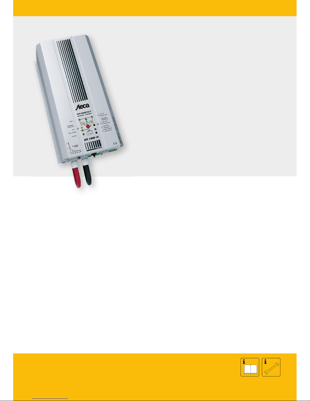
Sine Wave Inverter with Battery Charger and Transfer System
Sinuswechselrichter mit Batterielader und Transfersystem
Steca XPC
XPC 1400-12
XPC 2200-24
XPC 2200-48
714.828 | V5.5
PHOTOVOLTAIK - PHOTOVOLTAIC - PHOTOVOLTAIQUE - FOTOVOLTAICA
EN / DE
Page 2

Steca XP-COMPACT
XP-COMPACT V5.5 2/57
1 General Information.........................................................................................3
1.1 Operating instructions........................................................................................ 3
1.2 Quality and Warranty.........................................................................................3
1.3 Warranty Disclaimer........................................................................................... 3
1.5 Warning................................................................................................................4
2 Introduction........................................................................................................5
2.1 Principle schematic ............................................................................................5
2.2 Description of the main functions..................................................................... 6
2.3 Battery connecting..............................................................................................7
3 Mounting and installing.................................................................................. 8
3.1 Installation place.................................................................................................8
3.2 Fixing....................................................................................................................8
3.3 Connections......................................................................................................... 8
3.5 Cabling............................................................................................................... 11
3.6 Pre-installation settings....................................................................................11
4 Control............................................................................................................... 13
4.1 Display and control parameters......................................................................13
4.2 Display and control parameters on remote control panel (optional)......... 13
4.3 Light Emitting Diodes (LED)............................................................................14
4.4 Push buttons......................................................................................................15
4.5 Turning Knobs................................................................................................... 15
4.6 The Inverter....................................................................................................... 15
4.7 The battery charger.......................................................................................... 16
4.8 The Transfer system........................................................................................18
4.9 The Multifunctional Contact ............................................................................ 20
4.10 The Remote Control RCC-01......................................................................... 21
4.11 The Temperature sensor CT-35..................................................................... 21
5 Programming (possible only with the remote control RCC-01)......... 22
5.1 Standard setting................................................................................................22
5.2 Reset value (default settings).........................................................................22
5.3 Battery voltages and absorption time............................................................ 22
5.4 Auxiliary contact................................................................................................23
6 Installation Maintenance .............................................................................. 26
7 Declaration of CE Compliance .................................................................... 26
8 Technical Data................................................................................................. 27
Page 3

Steca XP-COMPACT
XP-COMPACT V5.5 3/57
1 General Information
1.1 Operating instructions
This manual is part of the delivery package of every XP-COMPACT inverter-charger.
It serves as guidelines for safe and efficient operation of XP-COMPACT. The
instructions are only valid for use with the following devices and options:
XP-COMPACT XPC 1400-12
XP-COMPACT XPC 2200-24
XP-COMPACT XPC 2200-48
Temperature sensor CT-35 AC cable cover CFC-01
Remote Control RCC-01 IP23 cover C-IP23
Solar charge controller XPC xxxx-xx-S
Every person who installs a XP-COMPACT and/or works with it must be fully familiar
with the content of this manual and must follow exactly all the warning and safety
instructions. Installation of or any work on the XP-COMPACT must be carried out by
a skilled and trained personnel. Installation and application must comply with the
respective local installations codes and safety regulations.
1.2 Quality and Warranty
During production and assembling, all XP-COMPACT appliances go through many
controls and tests. Production, controls and tests are carried out in accordance with
firm and established procedures. Every XP-COMPACT has its own serial number,
which helps to refer back to its original data in the event of controls or repairs. That is
why you should never remove the identification plate showing the serial number. The
warranty for these appliances is valid for uses and operating possibilities mentioned
in this manual.
The warranty period for the XP-COMPACT is 2 years.
1.3 Warranty Disclaimer
We do not accept any liability for any damages occurring through use, manipulation,
working situation and handling, which are not explicitly mentioned in these operating
instructions.
Following cases are not covered by the warranty:
− High voltage at INPUT (i.e. 48V at the Battery INPUT of XP-COMPACT 1400-
12)
− Reverse polarity on Battery connections (+/- reversed)
− Running liquid or oxidation through condensation in the appliance
− Defects caused by force, physical or mechanical means
− Changes not explicitly authorized by STECA
− Not or only partly tightened screws and nuts after change of fuses or cables
connecting
− Transport damage, i.e. through bad handling and /or packing
− Damage from atmospheric over voltage (lightning)
Page 4

Steca XP-COMPACT
XP-COMPACT V5.5 4/57
1.4 Liability Disclaimer
Respecting this manual, servicing and method of installation, functioning, application
and maintenance of the appliance can not be controlled or supervised by STECA.
Hence we do not accept any liability and responsibility for damages, losses and costs
which result through the use of this appliance or which result through incorrect
installation, incorrect operation or wrong application and maintenance, or which by
some other means maybe connected to each other.
The use of STECA’s inverters does exclusively involve the user’s liability.
This device is not designed for applications involving health care and medical
treatments where the patient life is concerned and where any mishap may be lethal.
Similarly, we do not accept any liability for any violation of the patents rights or
violation of any third party’s rights resulting from the use of this appliance
STECA reserves the right to modify the technical data or these operating instructions
without any prior notice.
1.5 Warning
This manual must be readily available for the user at any time. The user must be
familiar with the precautions and safety aspects in the country of installation.
During operation of XP-COMPACT, high voltages are generated at the connections
and inside of the appliance which could be lethal. Work on the appliance and on the
installation should only be carried out by skilled and trained people.
The whole installation connected with the XP-COMPACT must comply with the rules
and codes in force.
People without the written authorization from STECA are strictly forbidden to carry
out any change or repair on the appliances. For authorized changes only original
parts are to be used.
The XP-COMPACT may only be used when it has been installed in accordance with
these instructions and all parts have been correctly assembled and installed.
The XP-COMPACT may only be connected to lead-acid or lead-gel batteries.
Caution: Even when a XP-COMPACT has been disconnected from all
connections, at the OUTPUT point there could still be deadly voltages present.
To remove these voltages you must switch on the XP-COMPACT ON with the
ON/OFF switch. After one minute the electronics are discharged and any work
can now be safely carried out.
The XP-COMPACT is only suitable for internal use and under no circumstances
should it be subjected to snow, rain, or any other wet conditions.
By installations in motorized vehicles the XP-COMPACT must be protected from
water-spray and any other wet conditions.
Caution: In normal use lead-acid and lead-gel batteries give out explosive
gases. Never smoke or allow a spark or flame in the vicinity of batteries. The
batteries must always be stored or placed in a well ventilated room, they
should be placed in such a way that there is no danger of short-circuit through
carelessness. Never charge frozen batteries.
Page 5
Steca XP-COMPACT
XP-COMPACT V5.5 5/57
1.6 Special precautions
− While working on batteries there should always be a second person close to you
or within your voice range, in case help is needed.
− Plenty of fresh water and soap must be ready at hand so that in case of acid
coming in contact with skin, eyes and clothes, the areas in question can be
thoroughly washed.
− If acid enters the eyes, you must thoroughly wash them with cold running water
for at least 15 minutes. It is recommended that you immediately consult a
medical doctor.
− Baking powder neutralizes battery acid electrolyte. Always keep some at hand.
− Special care must be taken when working with metal tools near or on the
batteries. With tools such as screwdrivers, spanners etc. short-circuits can
result. Sparks produced by the short circuit can cause an explosion.
− When working on batteries all personal metal items such as rings, necklaces
and bracelets must be removed. Batteries are so powerful that short-circuit with
these items can melt them and thus cause severe burns. Always follow the
battery manufacturer instructions.
− Under certain conditions XP-COMPACT or a connected generator can start
automatically. While working on an electrical installation you must ensure that
these appliances are disconnected beforehand from the installation.
2 Introduction
The XP-COMPACT is a sine wave inverter with integrated battery charger with many
additional functions, it has been developed to be used as stand-alone (no gridfeeding) AC provider, or as continuous / break-free current supply provider (UPS).
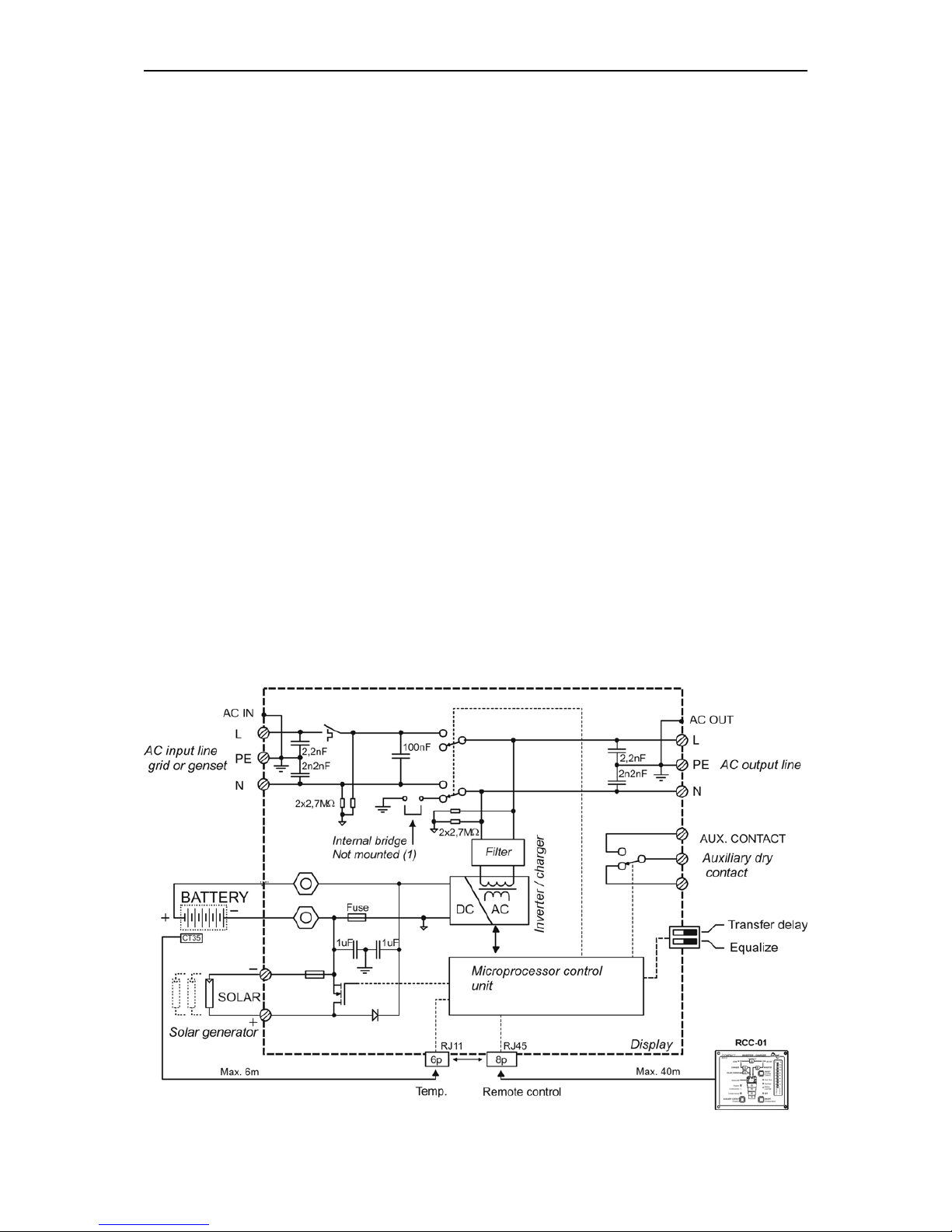
2.1 Principle schematic
Page 6

Steca XP-COMPACT
XP-COMPACT V5.5 6/57
Notes:
(1) The neutral of the appliance is not connected to the earth whatever the
function mode is. If requested and according to the local regulation, an automatic
connection between Neutral and earth in inverter mode only may be done by
installing a bridge internally to the unit. Please contact your installer regarding this
point.
(2) Remote control for remote adjustment of the input limit. (see chap. 4.6.3)
2.2 Description of the main functions
2.2.1 The inverter
The sine wave inverter XP-COMPACT generates a sinusoidal AC voltage with an
exceptionally precise voltage and stabilized frequency. In order to start large electric
motors, the user has the possibility to use a short surge power which is 3 times the
nominal power of the XP-COMPACT.
The inverter is protected against overload and short circuit. A power stage with the
latest MOS-FET power transistors, a toroidal transformer, and a fast regulating
system makes a robust and reliable inverter with the highest efficiency. A 1-20 Watt
adjustable charge detection system allows the smallest energy consumption and
ensures a long life for the battery.
2.2.2 The transfer system
XP-COMPACT can be connected to an AC source. For example a stand-by
emergency generator or the AC network. With the transfer system, on one side you
have an alternating voltage at the output for the use of consumer appliances. On the
other side the battery park is being charged. The distribution of energy between the
consumer appliances and battery charger is automatic.
2.2.3 The battery charger
The built-in battery charger is so designed that it can charge the battery quickly and
fully. A microprocessor controlled, Step charging process, ensures the optimal
charging of the battery. The desired charging current can be set continuously from 0
to 20/37/45 A, as per the model. The setting is made accordingly to the battery
capacity and power available.
The battery charger is designed for lead-acid and lead-gel batteries. Thanks to the
floating charge system the batteries can remain continuously connected.
2.2.4 Remote control
As an option, a remote control RCC-01 can be connected to XP-COMPACT. All
operating features and displays, save the adjustment levels (22/23/24/26), are
available on the remote control. It is supplied with a 20m long cable. This cable can
be up to 40m long. On the remote control, output power and charging current are
also displayed.
Page 7
Steca XP-COMPACT
XP-COMPACT V5.5 7/57
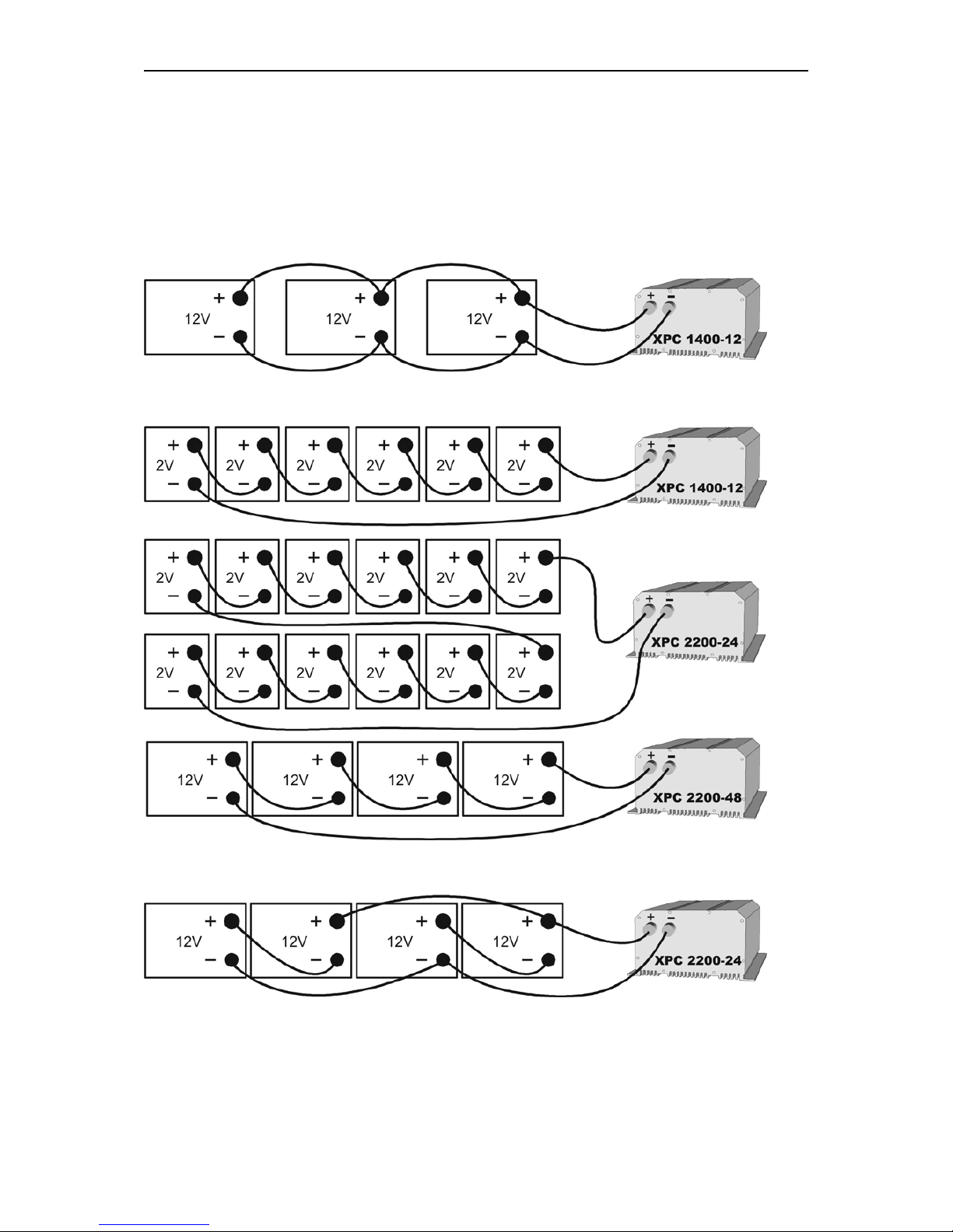
2.3 Battery connecting
Lead-acid batteries are normally available in blocks of 2V, 6V or 12V. In most cases,
to generate the necessary operating voltage and the capacity of the batteries for the
XP-COMPACT many batteries have to be connected together in parallel and or in
series. Here are 3 examples of connection:
2.3.1 Connection in parallel
2.3.2 Serial connection
2.3.3 Serial and parallel connection
Page 8
Steca XP-COMPACT
XP-COMPACT V5.5 8/57
3 Mounting and installing
3.1 Installation place
The location of the XP-COMPACT must be driven by the following criteria:
− Protection from unauthorized handling
− Dry dust free room, no condensation
− Never install directly over the battery and never in a cabinet together with the
batteries
− Keep ventilation holes free
− In mobile installations it is important to keep the vibrations down as low as
possible
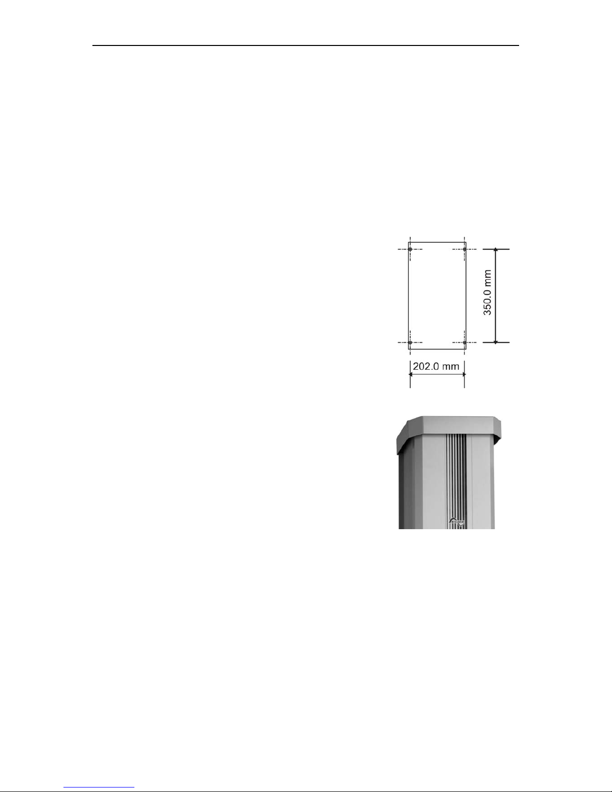
3.2 Fixing
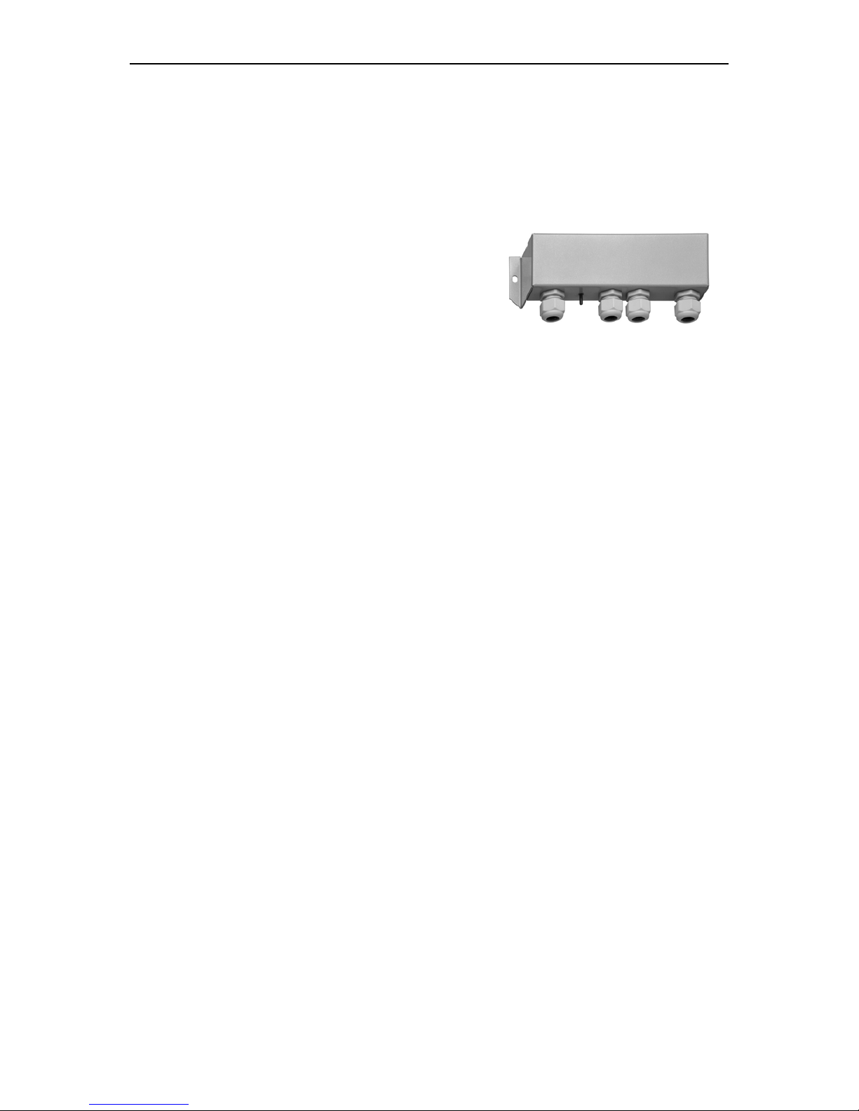
3.2.1 Fixing the XP-COMPACT
Basically the XP-COMPACT can be installed in any
desired location. Preferred is that the appliance be wall
mounted with battery cables downwards. The XPCOMPACT is fixed on the wall with four screws through the
four holes (diameter 5.5mm) which are accessible from the
outside. In motor vehicles XP-COMPACT must be fixed on
vibrations reducing elements. The XP-COMPACT must not
be fixed on a combustible base, as the back of the casing
can get hot and reach up to 80 degree Celsius.
3.2.2 Protection cover IP-23
This cover IP23 (Order ref. CIP-23) can be easily
installed after the fixation of the XP-COMPACT. For that
release a little the too screws down and more the tow up.
Then it’s possible to pass the IP 23 cover between the
XP-COMPACT and the wall. The cover must touch the
screws. Lock on the four screws, it’s ready.
3.3 Connections
3.3.1 General instructions on connecting
− The cable connection on the terminals AC INPUT / AC OUTPUT / 16A 230VAC
are carried out with a screwdriver Nr.1 and the connection on the SOLAR
terminal with a screwdriver Nr.2.
− The conductor cross section on the terminals AC INPUT / AC OUTPUT / 16A
230VAC of the connecting cable must be minimum 2.5mm2.
− All connecting cables and also the mounted battery cables, must be fixed with
strain relief clamps.
− The XP-COMPACT is delivered with battery cables already connected.
− The battery cables must never be extended. If the extension is unavoidable then
the conductor cross section must be elevated accordingly.
− To protect the battery cable, a fuse corresponding to the conductor cross
section must be fixed directly on to the battery.
Page 9
Steca XP-COMPACT
XP-COMPACT V5.5 9/57
− All cables must be tightly screwed in place. For safety, a yearly control is
recommended. In mobile installations control must be carried out more often.
− Connecting must be done by qualified personnel. Material such as cable,
connectors and distribution boxes, fuses etc. used in the installation must
comply with the respective valid low-voltage installation rules and regulations.
3.3.2 Protection cover of the terminals
connections
The protection is available as an option (Order ref.
CFC-01) and avoid to do wrong hazardous
connection on the terminals 230Vac. It mounted
with strain relief clamps for the cable.
Page 10
Steca XP-COMPACT
XP-COMPACT V5.5 10/57
3.4 Connection Plan
.
Caution:
Check battery
polarity (+/-) before connecting!
A wrong connection could
damage the system .
16A-250Vac
BATTERY
SOLAR
Remote
control
Temp.
Don't open before
disconnect line
and battery
N
AC Input
AC Output
L
Equalize
Transfer delay
Auxiliary Contact
PE
N
L
PE
M AL
B
C
D
E
FG
H
J
K
N
Page 11

Steca XP-COMPACT
XP-COMPACT V5.5 11/57
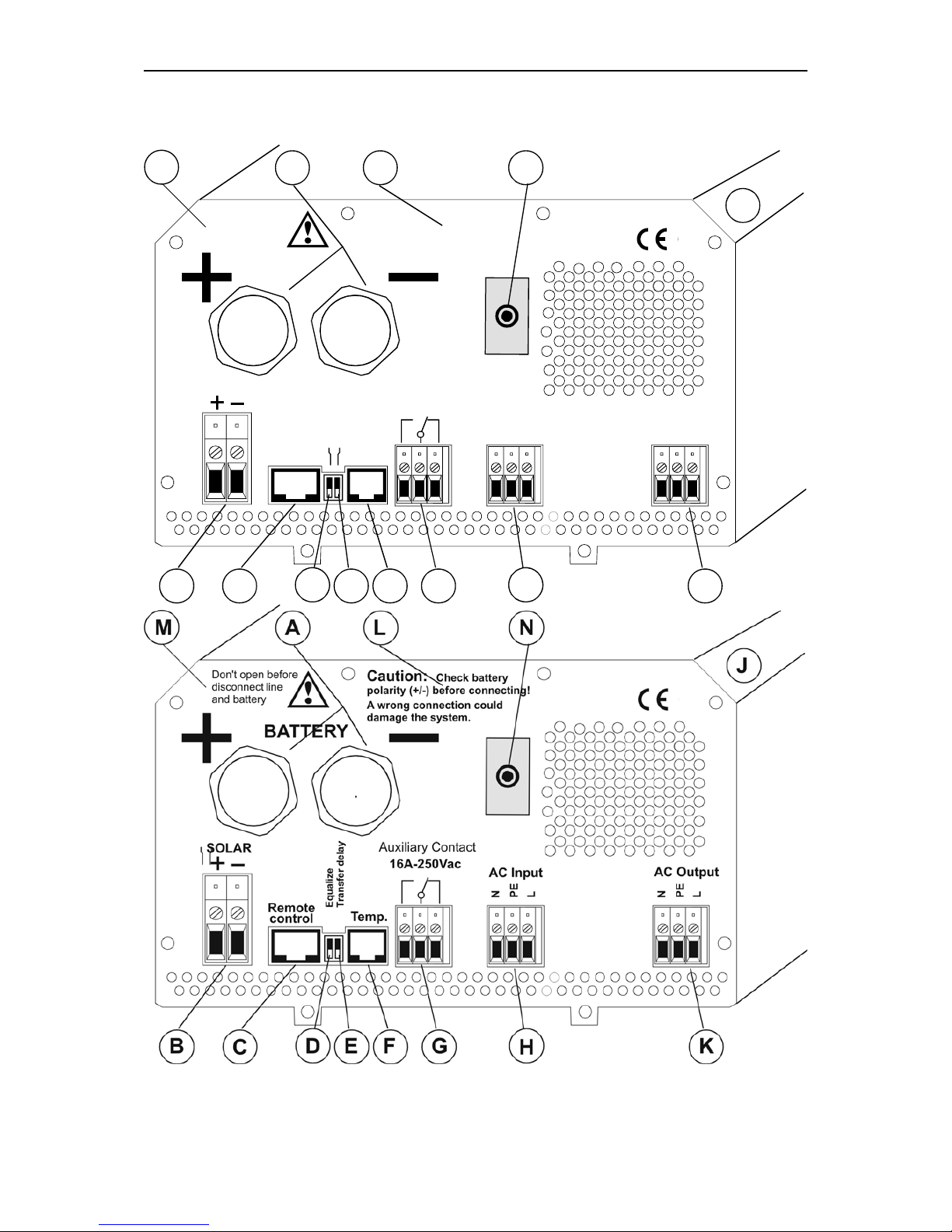
A Battery +/- Battery cable (already installed)
B SOLAR +/- Connection terminal for Solar modules, function not
offered
C Remote contr. Connection terminal for Remote Control RCC-01
D Transfer delay Slide switch for delayed opening of transfer
swichEqualize Slide switch for equalization of the
Battery
E Transfer delay Slide switch for Transfer DelayEqualize Slide switch
for equalization of the Battery
F Temp. Connection terminal for Temperature sensor CT-35
G Aux. Contact Connection terminal for Auxiliary Contact
H AC Input Connection terminal for AC-input. Located directly
above this terminal is the automatic safety cut-out for
this terminal.
J ID Plate Identification plate with Technical data and Serial
number
K AC Output Connection terminal for AC-output
L Caution… Caution: Check Polarity (+/-) before connecting the
battery !
M Don’t… Do not open without disconnecting all terminals
N 16A Protection 16A Protection switch for the Transfer system
3.5 Cabling
Connecting the XP-COMPACT is a very important step of the installation. You must
take care that all connection work is carried out in a clean and correct way and that
under no circumstance a cable is connected to a wrong terminal.
Connecting of the XP-COMPACT must be carried out in the following order. In case
of dismantling this order must be reversed.
3.6 Pre-installation settings
Before you start with the cabling of the XP-COMPACT you must set the type of
battery. In case sealed-gel batteries are used then you must set the small slideswitch „Equalize“ (E) which is on the front with the connection terminals, in OFF
position. In case of „normal“ lead-acid – batteries, these can handle a higher
equalizing charge, the same slide switch (E) can be set in ON position. In case of
doubt leave the setting in OFF position.
This will allow an equalizing cycle (higher end of charge voltage) during the next
charge process. Since then equalizing will occur every 25 usual cycles.
In case of doubt leave the setting in OFF position.
3.6.1 Connection to battery
Get the batteries ready for connection: Matching battery terminals, matching fuse on
a clamp. Prepare battery cables, if necessary press on cable tabs/shoes. Connect
red cable on Plus (+)-Pole and the black cable on the Minus (-) Pole. On connecting
the second cable to the battery pole a spark is produced, because for a short time
high current flows in the XP-COMPACT to charge the capacitors. For this reason
follow strictly the safety measures described in this manual. Check if the red LED
OFF (13) is lit. If it is not lit, press shortly on the switch ON/OFF (19), now OFF
should be lit.
Page 12

Steca XP-COMPACT
XP-COMPACT V5.5 12/57
On connecting the battery the XP-COMPACT needs 1 – 2 Minutes to calculate the
actual capacity of the battery. During this time the battery condition is shown as
100% charged. (LED 14 – 17 lit).
If the LED 12 Battery Low/High is lit, the battery charge is too low. If the LED 12
Battery Low/High is blinking, the battery charge is too high.
Caution: With a wrong battery voltage the XP-COMPACT can be destroyed. (for
example: connecting a XPC 1400-12 to a 48V-Battery).
Nevertheless, if the XP-COMPACT had been connected with reverse polarity, it is
highly probable that the fuse inside the casing is defect. Before opening the casing
cover all terminals must be disconnected including the battery. If the XP-COMPACT
does not function after the changing of the fuse and correcting of the polarity, it
means that it is defect and must be sent for repair.
3.6.2 Connection to the 230Vac-consumer appliances (AC OUTPUT)
The 230V consumer appliances must be connected to the terminals AC OUTPUT
with cables which cross section has to follow the local rules in force (usually
2.5mm2). Connections are marked as follows “N“ Neutral, “PE“ Earth (connected to
the appliance boxenclosure), “L“ Live.
Caution: High voltages can be there. Make sure that the XP-COMPACT is
turned off (LED 13 lighting) before the connection.
3.6.3 Connection to the 230Vac Input (AC INPUT)
The 230V-supply from network or from a generator must be connected to the input
terminals AC INPUT with cables which cross section depends on the power source
(usually 2.5mm2). Connections are marked as follows: “N“ Neutral, “PE“ Earth
(connected to the appliance case), “L“ Live (connected to the appliance case).
3.6.4 Connection to Auxiliary Contact
This contact is a potential free change over contact the currents and voltages allowed
for this contact are max. 16A/250Vac. The LED 5 “Contact active” shows the position
of them: alight mind active and off mind non-active. The schematic view of the
connections on the front, show the relay in the non-active mode.
3.6.5 Connection to Remote control
The Remote Control RCC-01 is connected in the terminal marked „Remote control“
with a 20m long cable and a RJ11/8 connector. The Remote Control can be plugged
IN or plugged OUT during any operation situation. Push in the connector softly until
you hear the „click“ showing that the connector is locked. The same applies to the
plug in the Remote Control.
The length of the cable for Remote Control should not exceed 40m. We deliver it with
20m cable.
3.6.6 Connection to Temperature Sensor (Temp.)
The temperature sensor CT-35 is connected in the terminal marked „Temp“ with a
3m long cable and a RJ11/6 connector. The temperature sensor can be plugged IN
or plugged OUT during any operating situation. Push in the connector softly until you
hear the „click“ showing that the connector is locked. The temperature sensor must
be glued to the wall of the battery or near it. The Temperature Sensor cable must
not be tied together with the battery cables or laid in a rope/bundle.
Page 13
Steca XP-COMPACT
XP-COMPACT V5.5 13/57
4 Control
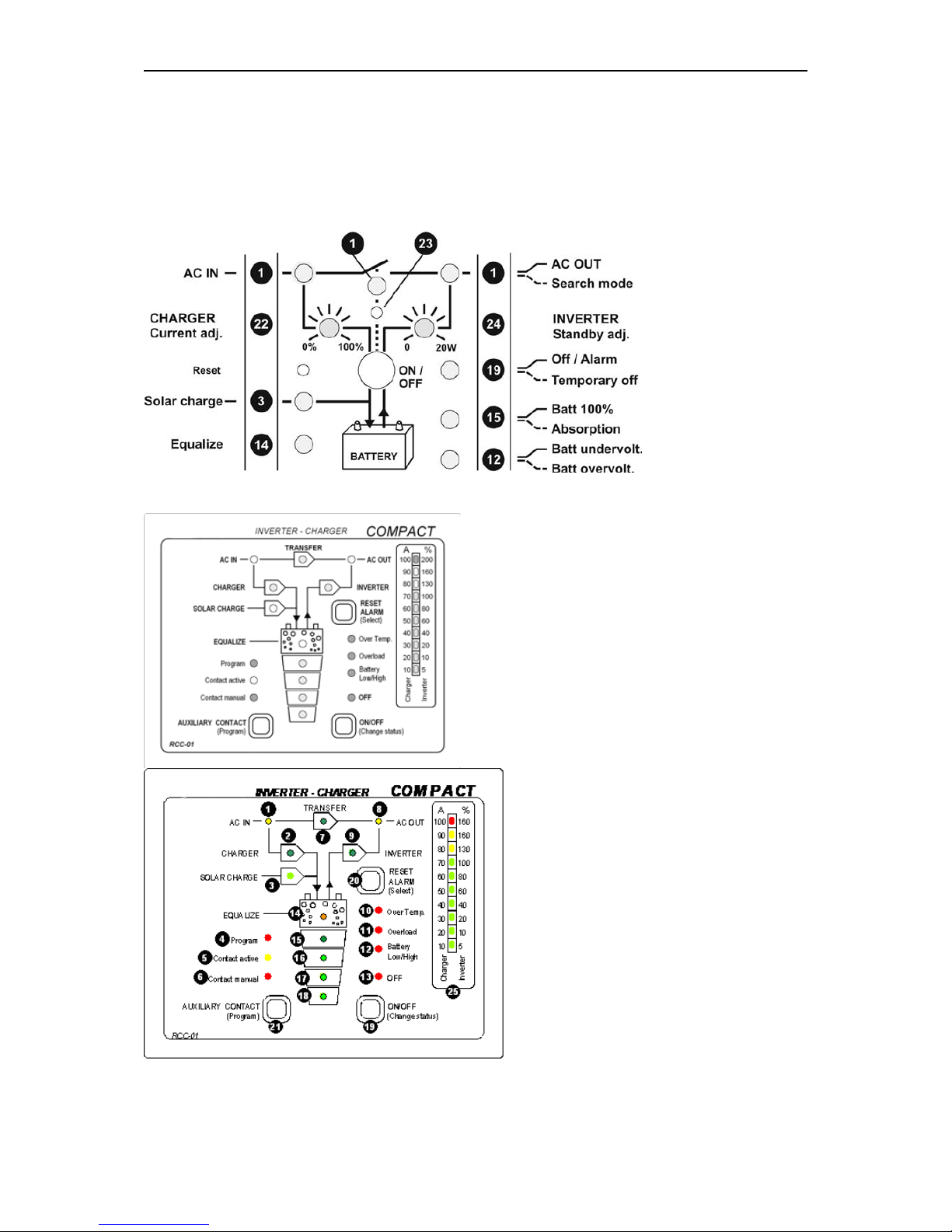
4.1 Display and control parameters
4.2 Display and control parameters on remote control panel (optional)
Page 14
Steca XP-COMPACT
XP-COMPACT V5.5 14/57
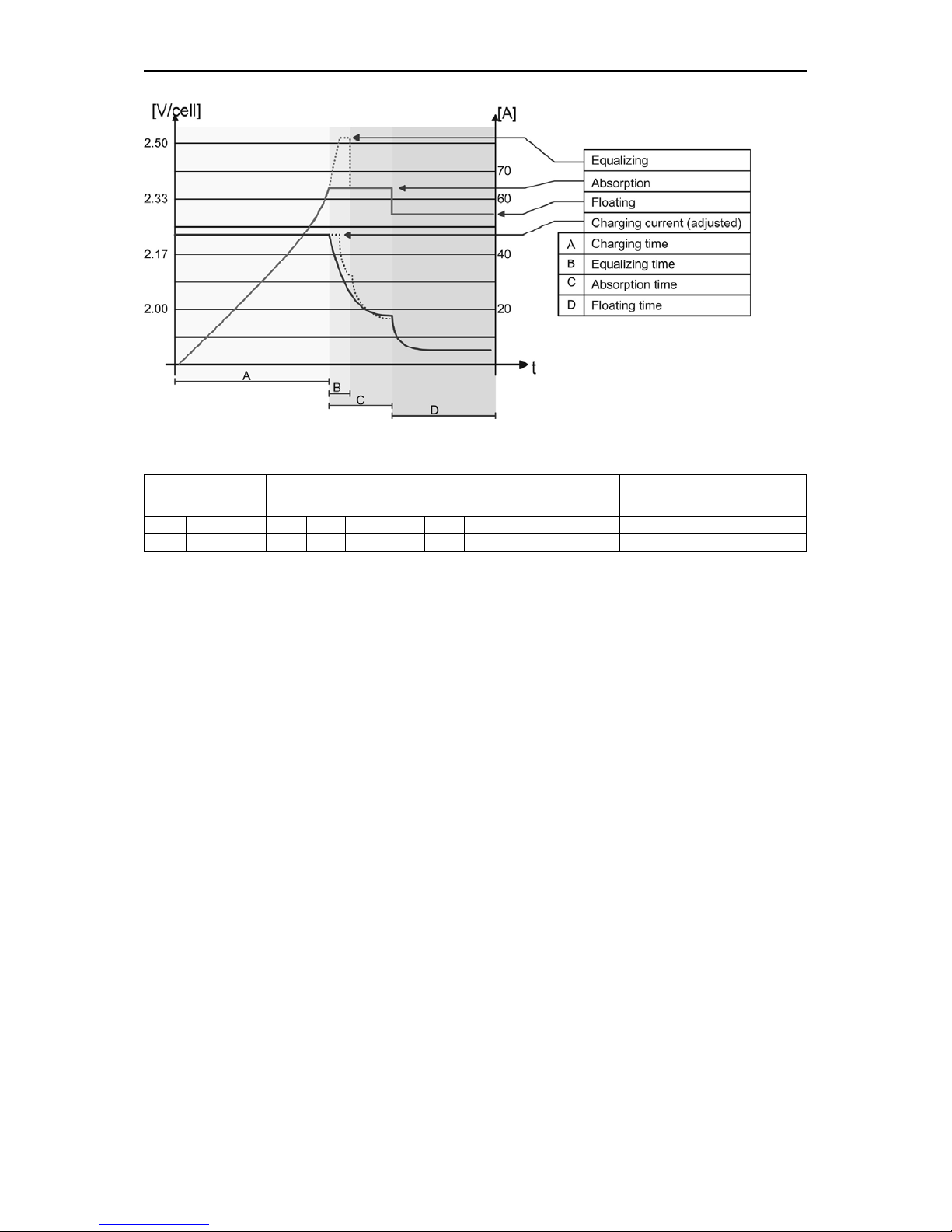
4.3 Light Emitting Diodes (LED)
LED Marking LED lit LED blinks
1 AC IN
Voltage
corresponding to
self-adjusted
values is at the AC
IN input.
A voltage outside the self-adjusted
values is at the AC IN input, or the XPCOMPACT is in synchronization
phases
2 CHARGER
Battery charger is
working
The battery charger is locked OFF
(see chap. 4.7) or provisory out of
order. In that last case it will restart
within 10 seconds
3
SOLAR
CHARGE
This function is not offered for the XP-Compact
4 Program
Program mode for
Aux. Contact
5
Contact
active
Auxiliary Contact is
activated
6
Contact
manual
Aux. Cont.
manually activated
7 TRANSFER
Transfer system is
active. In- coming
voltage is being
sent directly to AC
OUT outlet
Transfer (bypass) is disabled (see
chap. 4.8)
8 AC OUT
There is a voltage
at the AC OUT
outlet
The Inverter is in Standby-Mode
9 INVERTER Inverter is working Forced Inverter Mode (see chap. 4.6)
10 Over Temp.
For the time being
the XP-COMPACT
is out of service
because of
overheating.
11 Overload
The XP-COMPACT
is out of service
because of
overload or shortcircuit
12
Batt.
Low/High
Battery voltage is
too low
Battery voltage is or was to high
13 OFF
XP-COMPACT is
turned off. Turning
it back on is only
possible manually.
XP-COMPACT is for the time being
turned off. Turning it back on will
follow automatically !
14 EQUALIZE
Battery equalizing
is set
15–18
State of charge of
the battery
LED 15 – Absorption time is running
Page 15
Steca XP-COMPACT
XP-COMPACT V5.5 15/57
25
POWER
MONITOR
Display the value of the output power in % of Pnom (in
Inverter Mode) and the charge current in Amps (in Charger
Mode).
4.4 Push buttons
19 ON/OFF
Turning the XP-COMPACT on and off (Help Button for
Programming)
20 RESET Alarm Signal off (Help Button for Programming)
21 Aux. Contact Control Aux. contact (Help Button for Programming)
4.5 Turning Knobs
22 CHARGER Adjustment for max. Charging Current
23 TRANSFER
Adjustment for Transfer Voltage Threshold (TRANSFER –
INVERTER)
24 STANDBY Adjustment for „Standby“ system
4.6 The Inverter
An Inverter is built in the XP-COMPACT, which generates a sinusoidal alternating
voltage of a very high quality. With this Inverter any 230Vac alternating voltage
appliance up to the nominal power of your XP-COMPACT can be operated. Thanks
to the generous dimensioning of the XP-COMPACT, you can operate appliances
requiring higher power than the nominal power of the XP-COMPACT for a short time.
The XP-COMPACT provides up to 3-times the nominal power to start motors.
The Inverter mode is displayed through LED 9 (Inverter). If the Inverter Mode is
disabled (see chap. 5.5) LED 9 will blink. If the LED 9 is lit, the Inverter is in operation
and you have 230Vac at the output AC OUT. The actual power of the connected
appliance is displayed on the power monitor 25 and on the Remote Control.
4.6.1 Charge detection system „Standby“
In order to avoid unnecessary discharge of the battery, the inverter switches OFF
automatically if no appliance is connected and switches ON automatically again if
appliance is connected. The LED 8 blinks if the inverter is in Standby-Mode. The
switching-on/starting level can be adjusted with the turning knob 24 „STANDBY”.
Adjusting the switching-on level is as follows: Switch off all consuming devices, turn
the Turning Knob 24 to the right until the LED 8 is blinking, switch on the smallest
consuming device (i.e. Mobile phone charger), turn the Turning Knob slowly to the
left until LED 8 is lit.
If the Standby-Mode is not wanted, turn the Turning Knob 24 to the left, to the OFF
position.
4.6.2 Overload
If the Inverter is too long or too heavily overloaded, it switches off. The LED 11
„Overload“ is lit and LED 13 „OFF“ blinks. After ca. 10 seconds the Inverter switches
on automatically. If the Inverter is overloaded four times one after another in a short
time, then it no longer switches on automatically. The LED 13 remains lit. Press the
push button 19 „ON/OFF“ in order to switch on the Inverter.
Page 16

Steca XP-COMPACT
XP-COMPACT V5.5 16/57
4.6.3 Overheating (Over Temp.)
If the Inverter has been overloaded for a long time or it has been working in too high
surrounding temperatures, it will switch off. The LED 10 „Over Temp.“ is lit and the
LED 13 „OFF“ blinks. After cooling down, the inverter switches back on automatically.
One minute before the inverter switches off for too high temperature it gives out an
acoustic alarm signal. If the Auxiliary Contact has been programmed to detect the
high temperature then it synchronizes the relay with the alarm signal. In this way, for
example, an emergency back- up system can be started without any break in the
energy supply.
4.6.4 Battery Condition
Deep discharge of the lead-acid batteries leads to high losses in capacity and early
aging. That is why the battery condition is continuously controlled and supervised.
With low volt-age the inverter switches off. The LED 12 „L/H Batt.“ is lit and the LED
13 „OFF“ blinks. When the battery voltage gets up to 12.1V / 24.2V / 48.4V, the
Inverter switches on automatically. One minute before the Inverter switches off due to
low voltage it gives out an acoustic alarm signal. If the Auxiliary Contact has been
programmed to detect the low voltage then it synchronizes the Aux. Contact with the
alarm signal. In this way, for example, an emergency back up system can be started
without any break in the energy supply.
The low voltage is set to 11.6V / 23.2V / 46.4V. These settings are standard for most
batteries. These voltage levels are maintained by the built-in Battery-ManagementSystem of the XP-COMPACT by matching the load and the battery condition.
This setting is comparable with the levels of 10.8V/ 21.6V / 43.2 which are given
for most batteries at nominal load.
All voltage levels can be programmed. See the instructions under the section on
Programming. Check with your battery supplier which voltage values should be set.
4.7 The battery charger
4.7.1 Cycle of charge
The full automatic XP-COMPACT Battery Charger is adjusted at the factory so that
most lead-acid and lead-gel batteries can be charged to the maximum. As soon as
the minimum alternating voltage for the AC IN set on the Turning Knob 23 is available
at the input (LED 1 AC IN is lit), the Battery Charger is switched on automatically
(LED 2 CHARGER is lit). The battery is fully automatically charged matching to the
charge level, the adjusted volt-age levels and the charge current. Thanks to the builtin Float Charge System, the batteries can be left connected for unlimited time with
the Battery Charger switched on.
During the charging phase the appliances at the outlet AC OUT are continually
supplied with power (LED 8 AC OUT is lit).
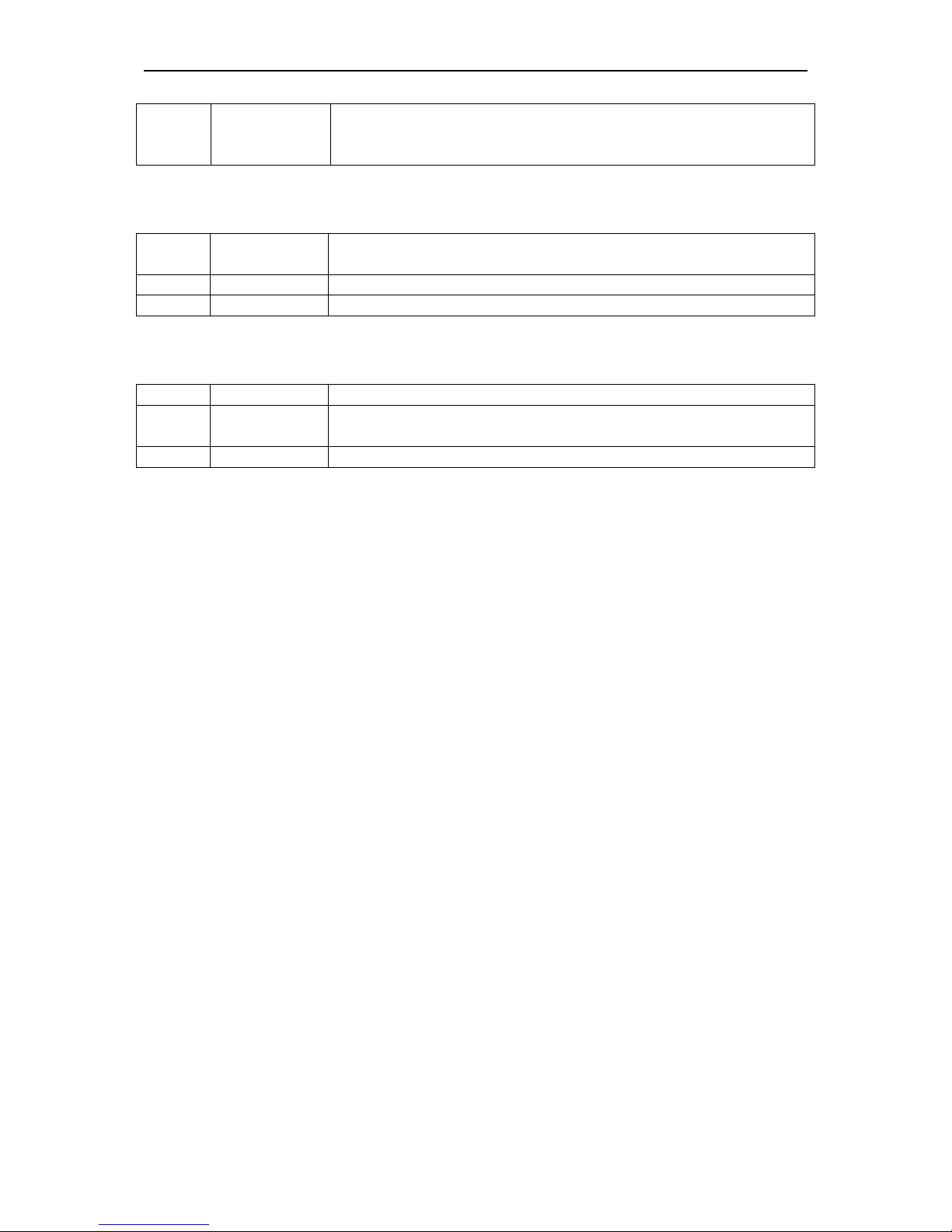
The charger functions are shown in the following diagram:
Page 17
Steca XP-COMPACT
XP-COMPACT V5.5 17/57
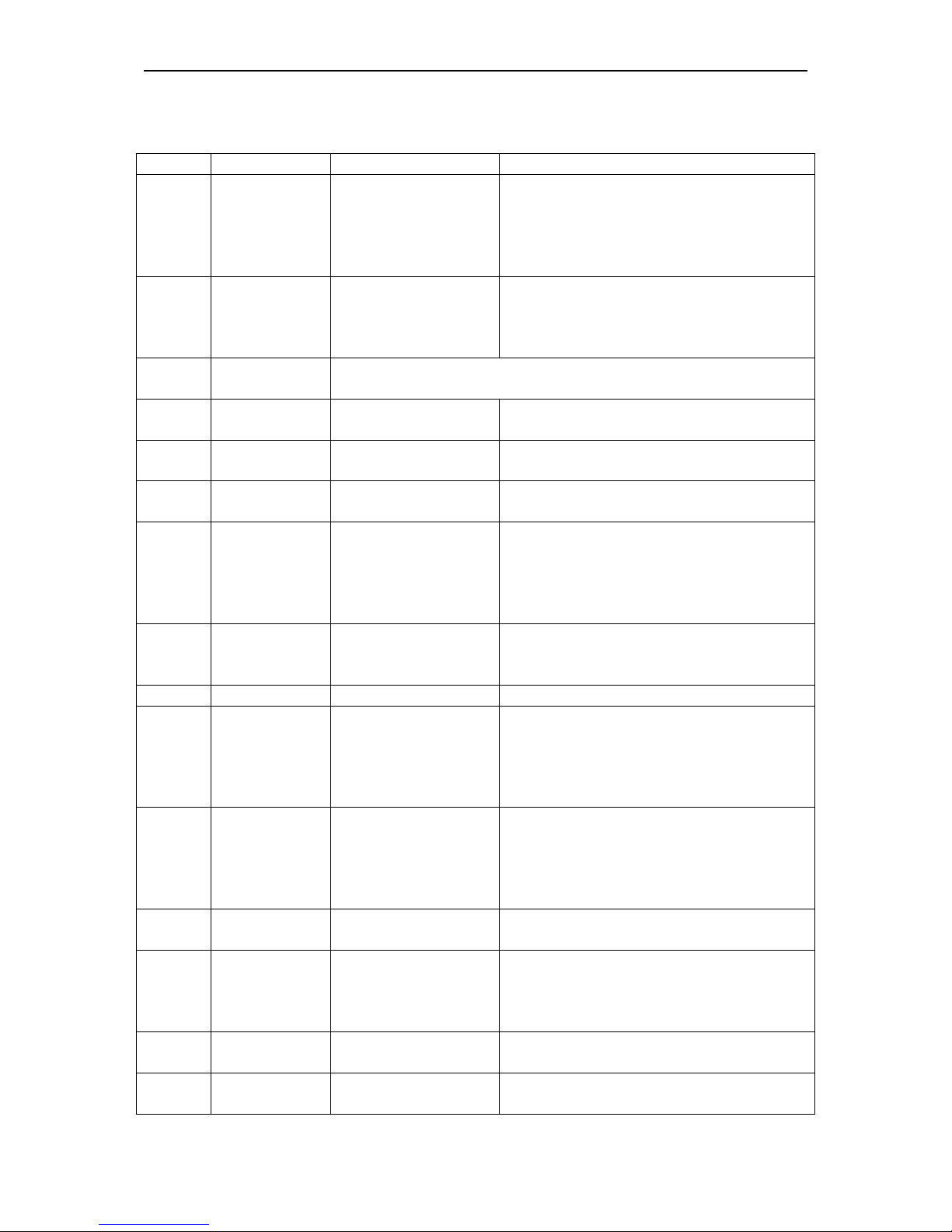
4.7.2 Default values for battery voltage thresholds
Low voltage Float charge Absorption Equalization
Absorption
time
Equalization
time
12V 24V 48V 12V 24V 48V 12V 24V 48V 12V 24V 48V 12/24/48V 12/24/48V
11.6 23.2 46.4 13.5 27.0 54.0 14.4 28.8 57.6 15.6 31.2 62.4 2h 20’
These values can be modified by mean of the optional remote control
4.7.3 Equalization charging
Before you program the XP-COMPACT for Equalization-charge you must check with
your supplier that the batteries are suitable for this process.
Equalization is recommended for the lead-acid batteries in order to mix well the
electrolyte fluid and to clean the lead plates.
If the XP-COMPACT is operating with a lead-acid battery, which is suitable for
equalization, the slide switch „Equalize“ which is on the cable connection side, must
be placed in the ON position. In this setting, every 25 charge cycles an equalization is
carried out for 20 minutes (factory setting). During such a charge cycle the LED 14 is
lit and during equalizing it is blinking. Charge cycle with equalization can be started
independently from the actual program. For this purpose the slide switch must be slid
from “OFF” to the “ON” position. The LED 14 will light up. If the periodic equalization
is not required, slide switch must be slid back to the „OFF“ position after the
completion of the manual cycle.
The equalizing voltage can be changed. How to proceed is explained in chap. 5.3.
Batteries not designed for equalize should never been charged this way.
CAUTION: During the equalization process, the batteries produce a lot more
gas. DANGER OF AN EXPLOSION !! The battery room must be well ventilated.
Equalization mode should never be used when using Gel-Batteries.
4.7.4 Charging current
The maximum charging current for the battery can be adjusted with the Turning Knob
22 (CHARGER). The charging current of the battery should be set to approximately
10 – 20% of the battery capacity (at C10). This means that the charging current for a
battery with 200Ah should be set between 20 – 40A.
The charging current is displayed on POWER MONITOR (25) of the front panel
or on the Remote Control.
Page 18
Steca XP-COMPACT
XP-COMPACT V5.5 18/57
4.7.5 Battery Condition
Built-in microprocessor with a specially developed algorithm calculates the actual
state of charge of the battery and displays it on LED 15 – 18. The LED 14 is lit when
the system is carrying out a charge cycle with equalization.
Notice: the exact measure of the battery state of charge with electrical parameters is
al-most impossible. The display of the state of charge is always more or less precise.
The measure system built in the XP-COMPACT takes into account the battery
voltage, the discharge and charge current as well as the undulation of the voltage. If
the battery and the XP-COMPACT are used according to their technical data, the
battery state of charge is displayed accurately. In the following cases of use the
display can diverge:
− Battery charge or discharge with too high
currents
− Battery cable cross section too small
− Battery connections badly tightened or
corroded
− Charge of the battery with external battery
charger
− Discharge of the battery with users not
connected to the XP-COMPACT
− Work with defective or sulphated batteries
This means that the display can, within few
minutes during the charge, commute from 25%
to 75% or during the discharge, to the opposite
direction.
As many of the working cases mentioned above often occur, the measure system of
the XP-COMPACT takes into account, during the charge, only the peaks of the
voltage undulation. As a consequence, the battery voltage at the start of the
absorption stage, measured by a voltmeter will appear deeper. By decrease of the
charge current the voltage will reach the exact values.
For safety reasons, you must get the recommended charge voltage and charge
currents from your battery supplier. The voltage levels and charge characteristics can
be changed through Programming. The instruction for programming of battery
charger is in the section „Programming“ (Chap. 5.3). The correct charging is
mandatory for a safe function and a long-life of the battery.
The battery charger functions are described by the graphic in chap. 4.7.1.
4.8 The Transfer system
When an AC voltage is at the input AC IN of the XP-COMPACT, the LED 1 AC IN is
lit. When this voltage matches the lowest adjusted value set by the Turning Knob 23
TRANSFER, and the frequency is between 44Hz and 65Hz, this voltage is switched
directly to the battery charger and to the output AC OUT. The LED 7 TRANSFER is
lit. The inverter is switched off and the battery charger switched on. This process is
automatic, unless the charger mode or the transfer mode is disabled (see Chap. 5.5).
The maximum current of the Transfer switch is 16A. That means through this system,
consuming devices up to a maximum of al 3700 Watt can be operated. When the
Battery Charger is working, part of this power is used for charging according to the
power sharing system.
Page 19

Steca XP-COMPACT
XP-COMPACT V5.5 19/57
The Transfer system is protected against overload with a circuit breaker on the AC
Input side of the XP-COMPACT. If the system has been overloaded, the button/pin of
the fuse will pop out. To put the automatic safety system back in to operating you
must push this pin back.
Note: in the Inverter operation, The XP-COMPACT generates a true sinusoidal and
quartz stabilized output voltage. However if the XP-COMPACT is supplied from a grid
or a generator and the transfer contact is active, then you have at the output AC OUT
the same voltage as that at the input. This voltage can not be modified by the XPCOMPACT !
4.8.1 Set the transfer voltage threshold
The voltage threshold of the transfer can be adjusted between 150 to 230V with the
turning knobs (23). From factory this value is 200V. Most appliances can work on this
voltage. When the Input voltages reach the selected value on turning knob, the
inverter switches off and the AC INPUT goes directly on the AC OUTPUT. When the
voltage INPUT is less of 20V the value set, the transfer is stopped and the OUTPUT
switches back on the inverter.
Note : Don’t use the turning knobs “TRANSFER” (23) to adjust the AC OUTPUT
voltage ! This is only it’s only a voltage threshold level to enable or disable the
transfer.
4.8.2 FAST (UPS)- MODE for the Transfer Switch
The quick and break free Transfer mode is programmed with a slide switch „Transfer
De-lay“ OFF, which is on the front side (cable connections side).
The aim of the XP-COMPACT is to supply the appliance with a break-free alternating
volt-age. When the incoming voltage AC IN no longer matches values which have
been set with the Turning Knob 23, the inverter switches on at once. The transfer is
carried out in 0.02 seconds. This quick transfer ensures a break-free function for
most appliances. If you have an alternating voltage back at the input AC IN, transfer
system starts up again with-out any break, and the inverter is stopped.
4.8.3 Delayed mode of the Transfer System
The delayed mode of the transfer system „Transfer Delay ON“ is programmed with
the slide switch (D) on front with the cable connections. The XP-COMPACT provides
a break-free alternating voltage for the appliance. A quick transfer switch is not
always sensitive nor is it always desired. For exampleI.E., when the appliances are
operated by a small back-up generator. An overload of a short period on such a
generator, i.e. start of a vacuum cleaner etc., has the effect of decreasing the voltage
for a short time. As in such cases the transfer to the Inverter is not desired, the
transfer system can be programmed with a delay. When the slide switch “(Transfer
delay” (D) is in the „On“ position, the transfer to the inverter takes place with a delay
of 5 seconds. If the voltage falls below 100Vac, the transfer takes place without delay
! The transfer switching to the Inverter takes place without any break.
Page 20

Steca XP-COMPACT
XP-COMPACT V5.5 20/57
4.9 The Multifunctional Contact
In the XP-COMPACT there is a built-in programmable power relay. The potential-free
change-over contact (NO – NC) of this power relay is connected to the screw
terminal AUX CONTACT.
Maximum Contact load: 230Vac / 12Vdc / 24Vdc / 16A !
> 36Vdc / 3A !
With the Push Button 21 „AUXILIARY CONTACT“ the contact can be manually
switched on or off independently from programming and from the operating situation.
The LED 5 “Contact active” shows the status of the contact. The drawing up the
screw terminal “AUX CONTACT” is the inactive position mode, LED 5 “Contact
active” off.
The switching on and off of this contact can be freely programmed for every
operating situation of the XP-COMPACT witch situation is indicated with a LED.
There is no limitation to its application and it is left to your wishes as to where and
how you would like to use it. The example and the setting of this contact are
explained in chapter 5.4.
In factory we program this for a dysfunction alarm. The contact is active when one of
these situations is detected:
− Over temperature (LED 10 lit)
− Overload (LED 11 lit)
− Over or less voltage of batteries (LED 12 lit or blinking)
− XP-COMPACT is turned off manually or with a fault (LED 13 lit)
In case this function is not wished, it must be modified by programming according to
procedure in chap. 5.4.
Page 21

Steca XP-COMPACT
XP-COMPACT V5.5 21/57
4.10 The Remote Control RCC-01
As an option, a Remote Control
can be connected to the XPCOMPACT. All operating controls
and displays except from level
adjustment are available on the
Remote Control. The Remote
Control is supplied with a 20m long
cable. It can as long as 40m. The
Remote Control is suitable for
surface mounting on the wall or on
to a switch board. It is fixed with 4
screws. The XP-COMPACT can
also be programmed with the
Remote Control. The Programming
is descry-bed in the section
„Programming“.
The output power and the charging currents are displayed on the Remote Control.
In the Remote Control there is an additional Alarm Contact and a built-in Control
Input. These two functions are available through Tip-jack RJ11/4 for use. This
Auxiliary Contact is Front / Work
Contact (max. 0.5A!), which is
independent from the Auxiliary
Contact of the XP-COMPACT.
This con-tact is active in case of
an alarm of the XP-COMPACT.
The Control Input is connected in
parallel to the ON/OFF- push
button. The XP-COMPACT can
be switched on or off through this
input with an impulse button or an
impulse contact.
Caution: No external voltage
should be connected to this
Input Control.
Order Number for Remote Control: RCC-01
Dimensions: H x B x T / 111.5 x 136.5 x 25mm
4.11 The Temperature sensor CT-35
Operating voltage of lead-acid batteries change depends
on the temperature. To correct the operating voltages
according to the actual temperatures, a temperature
sensor can be connected to the XP-COMPACT.
The compensation through the sensor is –3mV/°C/Cell.
Order Number: CT-35
Dimensions: H x B x T / 58 x 51.5 x 22mm
Page 22

Steca XP-COMPACT
XP-COMPACT V5.5 22/57
5 Programming (possible only with the remote control RCC-01)
The XP-COMPACT (except for 60Hz versions) is equipped with a Flash
processor fitted out with a Flash EEPROM Memory, which means that even
when it is disconnected from the battery, the parameters that were
programmed for the application remain after a new connection to the battery.
It is possible to reinitialize (RESET) the XP-COMPACT by pressing the small
black button on the left of the On/Off or by pressing simultaneously on the
three push buttons 19/20/21 of the remote control during at least 2 seconds. A
beep will confirm the RESET. The inverter switches off after this operation. It
can be turned on again after the beep. The programmed parameters will
remain.
5.1 Standard setting
The XP-COMPACT is delivered with the following default settings:
Auxiliary contact: active in case of defect or manual turn off with the LED 10/11/12/13
Battery voltage : Low voltage 11.6V / 23.2V / 46.4V
Float Charge 13.5V / 27.0V / 54.0V
End of Charge Voltage 14.4V / 28.8V / 57.6V
Equalization 15.6V / 31.2V / 62.4V
Absorption Time : 2 Hours
Equalizing Time : 20 Minutes
5.2 Reset value (default settings)
To come back to the default settings, press simultaneously on the push buttons
20/21 during at least 2 seconds. A beep will confirm the comeback to the factory
settings. The inverter switches off after this operation. It can be turned on again after
the beep.
5.3 Battery voltages and absorption time
5.3.1 Set the voltage and timing threshold
The programming is done in accordance with
the following steps:
Push and hold down, the Push Button 21
(Program) and the Push Button 19 (Change
status) for minimum 2 seconds
simultaneously.
With the Push Button 20 (select) select which
of the battery level and of the absorption time
have to be changed.
These four red LED’s show the function set:
Low voltage LED 13 (ON/OFF)
Float charge LED 12 (Batt. Low/high)
Absorption (End of charge) LED 11 (Overload)
Equalization LED 10 (Overtemp.)
Absorption Time LED 10/11/12/13 (altogether)
Page 23

Steca XP-COMPACT
XP-COMPACT V5.5 23/57
With the Push Button 19 (Change status) set the desired parameter (voltage or time)
to modify (LED 14/ 15/16/17/18). Push Button 19 (Change status) to set the desired
value according to the table 5.3.2.
If desired, repeat the operation with any other parameter (voltage or time) to be
changed.
If during 30 seconds no buttons are pressed, the selected values are automatically
stored and the XP-COMPACT switches back in to the normal operating status.
The voltage levels and times changed through programming are only first active with
the next charge cycle!
The voltage level which is not suitable can greatly reduce the battery life or
could even destroy it ! Therefore check beforehand with your battery supplier.
5.3.2 Table of voltage and timing threshold
The voltage levels (low voltage, float charge, end of charge and equalization) and the
duration of the absorption charge can be changed.
The display of these voltages and the times in the program mode are in accordance
with the diagram shown below:
Low voltage Float charge Absorption Equalization
Absorption
time
Equali-zation
time
LED
LED 13 LED 12 LED 11 LED 10
LED
10/11/12/13
LED 10/11
12 24 48 12 24 48 12 24 48 12 24 48 12/24/48 12/24/48
14
12.0 24.0 48.0 13.7 27.4 54.8 16.2 32.4 64.8 16.2 32.4 64.8 4h 3h
15
11.8 23.6 47.2 13.6 27.2 54.4 15.6 31.2 62.4 15.9 31.8 63.6 3h 2h
16 11.6 23.2 46.4 13.5 27.0 54.0
15 30 60
15.6 31.2 62.4 2h
1h
17
11.4 22.8 45.6 13.4 26.8 53.6
14.4 28.8 57.6
15.3 30.6 61.2 1h 40’
18
11.2 22.4 44.8 13.3 26.6 53.2 14.2 28.4 56.8 15 30 60 0 – 1’
20’
The heavy printed values show the standard settings.
5.4 Auxiliary contact
5.4.1 Principle
The Auxiliary Contact can be basically programmed for any operating situation of the
XP-COMPACT which is indicated with a LED. The programming is possible for one
or more operating situations. If the contact is programmed for many situations, it is
activated as soon as the XP-COMPACT finds itself in any one of the programmed
situations. That means that the work of the contact meets that of the logic OR–
Function.
5.4.2 The programming of the Auxiliary Contact
The programming of the Auxiliary Contact is carried out in the following Steps:
− The Push Button 21 (Program) presses down for min. 2 seconds. The LED 4
„Program“ is lit as an indication, that the XP-COMPACT is in program mode.
− A blinking LED shows the programmed condition for the auxiliary contact (LED
10/11/ 12/13 factory setting).
− With the Push Button 20 (select), select the desired condition in which the
contact should be activated.
− With the Push Button 19 (Change status) confirm or change the status for this
condition. If desired, with the Push Button 20 (select) select another condition in
which the contact should be activated.
Page 24

Steca XP-COMPACT
XP-COMPACT V5.5 24/57
− With the Push Button 19 (Change status) confirm or change the status for this
condition. If during 30 seconds no buttons are pushed, then the settled values
are automatically stored and the XP-COMPACT switches back to normal
operating condition.
5.4.3 Auxiliary Contact as generator starter
As per the battery capacity
When in the programming of the Auxiliary Contact, the Battery Capacity (LED 15-18)
is used as a condition, you must then take note of the following requirements.
If you have to start an emergency back-up supply with a battery having a certain
residual capacity, then two battery levels must be programmed. The first (i.e. Battery
25% LED 17) for the starting or activating the Auxiliary Contact and the second (i.e.
Battery 100% LED15) for stopping or disabling the Auxiliary Contact. Programmed
like this the Auxiliary Contact works with the lowest set condition and stops when it
has reached the highest programmed condition through charging.
Example: start of a generator with the XP-COMPACT
In order to program the auxiliary contact to start at 25% and to stop at 75% of the
battery state-of-charge, here is the procedure to follow:
− Press the key AUX. CONTACT (Program) 21 during at least 2 seconds. Then
the states will be displayed blinking (factory settings LED’s 10/11/12/13). As
these states are not wished for the start of the generator, they must be disabled.
− With the key (select) 20, select the LED’s to disable (the active LED’s are
blinking) and disable them with the key 19 Change Status. Select the other
LED’s to switch off with the key (select) 20 and switch them off with the key 19
Change Status until all are disabled.
− Then select the LED 17 with the key (select) 20 and activate the contact with the
key 19 Change Status. The generator will start once the LED 17 switches of.
− Then select the LED 16 with the key (select) 20 and activate the contact with the
key 19 Change Status. The generator will stop once the LED 16 switches on.
− If no key is activated during 30 seconds, the normal operation states are
displayed automatically again.
For a control the key Program can be pressed at least 2 seconds. The values set are
displayed blinking.
5.4.4 Power cut of the second priority loads
The auxiliary contact can also be used to cut the power of less priority loads when
the battery state of charge is lower than a given threshold. In that case, only one of
the battery state of charge, or the “transfer” function will be programmed as power cut
criteria.
The second priority loads will be supplied only when the generator is ON or when the
battery has a sufficient threshold.
5.4.5 Manual operating of Auxiliary Contact
The Auxiliary Contact can be operated at any time with the Push Button 21 (AUX.
CONTACT). The LED 6 „Contact manual“ lights up as information that the Contact is
manually operated, and LED 5 „Contact active“ lights up when the Contact is active.
By pushing the Push Button 21 a second time, the Contact is disabled. By pushing it
the third time, automatic functions are restored.
Page 25
Steca XP-COMPACT
XP-COMPACT V5.5 25/57
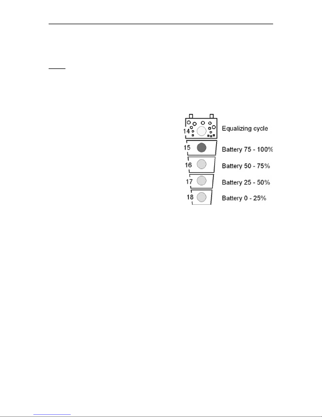
5.5 Disabling some of the XP-COMPACT functions
Each different function charger, inverter and transfer can be disabled. This is useful
for specific applications witch required to disable some of these three functions.
If you press the buttons 19 and 20 more than 2 seconds you can have access to the
different possibilities, shown in the following diagram.
In programming mode the display shows only the different types of program with the
three LED’s 2, 7 and 9 to each function. To change the type of programming, press
shortly the button 20 until you reach the right function used according to the table
below. After 10 seconds the XP-COMPACT exits the programming mode and loads
the new change.
In user mode, the disabled functions are displayed by blinking LED. So you can see
which mode is disabled.
5.5.1 Diagram of the different modes
Shows an off LED
Shows a blinking LED
Shows a lighted LED
All the functions are enabled. This is the
factory setting.
The inverter is disabled. Only the transfer
switch and the charger will work normally.
Inverter and charger are both disabled.
Only the transfer switch function is enabled in input voltage and frequency is OK
Charger and transfer switch are disabled
the inverter will work continuously even if
there is a correct AC voltage at the input.
Page 26

Steca XP-COMPACT
XP-COMPACT V5.5 26/57
6 Installation Maintenance
Apart from the periodic controls mentioned for the connections, the XP-COMPACT
does need any maintenance. Keep the appliance clean and from time to time, wipe it
clean with a damp cloth.
7 Declaration of CE Compliance
Hereby we state that the products described in this user manual comply with the
following standards:
EN 61000-6-1, EN 61000-6-3, EN 55014, EN 55022, EN 61000-3-2, Dir.
89/336/EEC, LVD 73/23/EEC, EN 50091-2, EN 60950-1.
CH - 1950 Sion, the 1st of March 2003 STUDER INNOTEC (R. Studer)
Page 27

Steca XP-COMPACT
XP-COMPACT V5.5 27/57
8 Technical Data
Page 28

Steca XP-COMPACT
XP-COMPACT V5.5 28/57
1 Allgemeine Informationen ______________________________________ 29
1.1 Zu dieser Bedienungsanleitung......................................................................29
1.2 Qualität und Garantie....................................................................................... 29
1.3 Garantieausschluss..........................................................................................29
1.4 Haftungsausschluss.........................................................................................30
1.5 Warnungen........................................................................................................30
1.6 Besondere Schutzmassnahmen....................................................................31
2 Einführung____________________________________________________32
2.1 Prinzip Schema................................................................................................. 32
2.2 Beschreibung der Hauptfunktionen............................................................... 32
2.3 Batterie Verschaltungen..................................................................................33
3 Montage und Installation_______________________________________ 35
3.1 Ort der Montage................................................................................................35
3.2 Befestigung........................................................................................................35
3.3 Anschluss........................................................................................................... 35
3.4 Anschlussplan / Frontseite.............................................................................. 37
3.5 Verdrahtung....................................................................................................... 38
3.6 Voreinstellungen...............................................................................................38
4 Bedienung____________________________________________________40
4.1 Anzeigen und Bedienelemente ...................................................................... 40
4.2 Anzeigen und Bedienelemente für der Fernsteuerung (Remote control) 41
4.4 Tasten................................................................................................................. 43
4.5 Drehknöpfe........................................................................................................43
4.6 Der Wechselrichter........................................................................................... 44
4.7 Der Batterielader............................................................................................... 45
4.8 Der Umschaltautomat (Transferschalter)......................................................47
4.9 Der Multifunktionskontakt................................................................................ 48
4.10 Die Fernsteuerung RCC-01............................................................................49
4.11 Die Temperatursonde CT-35.......................................................................... 50
5 Programmierung (nur mit Fernsteuerung RCC-01 möglich)_______50
5.1 Standardeinstellungen.....................................................................................50
5.2 Zurücksetzen der Programmierung (Standardeinstellung)........................ 50
5.3 Batteriespannungen und Absorptionsdauer................................................. 51
5.4 Hilfskontak
t........................................................................................................52
5.5 Sperren von Funktionen..................................................................................54
6 Wartung ______________________________________________________ 55
7 Konformitätserklärung CE _____________________________________55
8 Technisch
e Daten _____________________________________________ 56
Page 29

Steca XP-COMPACT
XP-COMPACT V5.5 29/57
1 Allgemeine Informationen
1.1 Zu dieser Bedienungsanleitung
Diese Anleitung ist ein fester Lieferbestandteil jedes Kombiwechselrichters XPCOMPACT. Sie dient als Richtlinie für den sicheren und effizienten Betrieb des XPCOMPACT. Die Anleitung ist nur gültig für die folgenden Geräte und Optionen:
XP-COMPACT XPC 1400-12
XP-COMPACT XPC 2200-24
XP-COMPACT XPC 2200-24
Temperatursonde CT-35 AC-Kabeleinführung CFC-01
Fernsteuerung RCC-01 IP-23 Abdeckung C-IP23
Solarladeregler XPC xxxx-xx-S
Jede Person, die einen XP-COMPACT installiert und/oder mit einem XP-COMPACT
arbeitet, muss vollständig mit dem Inhalt dieser Anleitung vertraut sein und strikt alle
Warn- und Sicherheitshinweise befolgen. Die Installation des XP-COMPACT und
Arbeiten daran müssen von qualifiziertem und dafür ausgebildetem Personal
ausgeführt werden. Installation und Anwendung müssen in jedem Fall den jeweiligen
örtlichen Installations- und Sicherheitsvorschriften entsprechen.
1.2 Qualität und Garantie
Während der Produktion und der Montage der XP-COMPACT durchlaufen sämtliche
Geräte mehrere Kontrollen und Tests. Fabrikation, Kontrollen und Tests erfolgen
gemäss genau festgelegten Protokollen. Jeder XP-COMPACT hat seine eigene
Seriennummer, welche dazu dient bei eventuellen Kontrollen oder Reparaturen auf
die genauen Gerätedaten zurückzugreifen. Entfernen Sie darum nie das Typenschild
mit der Seriennummer. Die Garantie für dieses Gerät gilt für die in dieser
Betriebsanleitung aufgeführten Anwendungen und Betriebsfälle.
Die Garantiedauer für die XP-COMPACT beträgt 2 Jahre.
1.3 Garantieausschluss
Für Schäden, welche durch Anwendungen, Manipulationen, Betriebsfälle und
Behandlungen entstehen, welche nicht ausdrücklich in dieser Betriebsanleitung
aufgeführt sind, können keine Garantieleistungen gewährt werden.
Nachfolgend eine Liste von Fällen für welche explizit keine Garantie gewährt wird.
− Überspannungen an den Eingängen (z.B. 48V am Batterieeingang des XPCOMPACT 1400-12)
− Verpolung bei Batterieanschluss(+/- vertauscht)
− In das Gerät eingelaufene Flüssigkeiten oder Oxydation durch Kondensation
− Defekte durch mechanische Einflüsse
− Nicht ausdrücklich von Steca Elektronik GmbH autorisierte Änderungen
− Nicht oder nur teilweis e festgezogene Schrauben und Muttern nach Wechseln
von Sicherungen oder Anschlusskabeln.
− Transportschäden, z.B. durch unsachgemässe Behandlung oder Verpackung
− Schäden durch atmosphärische Überspannungen (Blitzschlag)
Page 30

Steca XP-COMPACT
XP-COMPACT V5.5 30/57
1.4 Haftungsausschluss
Die Einhaltung dieser Betriebsanleitung und der Bedingungen und Methoden der
Installation, dem Betrieb, der Verwendung und der Wartung dieses Gerätes können
von der Firma Steca Elektronik GmbH nicht kontrolliert oder überwacht werden.
Daher übernehmen wir keinerlei Haftung und Verantwortung für Schäden, Verluste
und Kosten, die aus dem Betrieb dieses Gerätes entstehen oder die aus fehlerhafter
Installation, unsachgemässem Betrieb oder falscher Verwendung und Wartung
entstehen oder in irgendwelcher Art und Weise damit zusammenhängen. Ebenso
übernehmen wir keine Verantwortung für patentrechtliche Verletzungen oder
Verletzung anderer Rechte Dritter, die aus der Verwendung dieses Gerätes
entstehen.
Der Einsatz und Betrieb von Geräten von Steca obliegt in jedem Fall der
Verantwortung des Kunden.
Die in dieser Beschreibung erwähnten Geräte sind nicht für den Betrieb von
lebenserhaltenden Systemen einzusetzen.
Die Firma Steca Elektronik GmbH behält sich das Recht vor, Änderungen der
technischen Daten dieses Gerätes oder dieser Betriebsanleitung ohne vorherige
Mitteilung oder Ankündigung vorzunehmen.
1.5 Warnungen
Diese Betriebsanleitung muss so aufbewahrt werden, dass sie den Benutzern
jederzeit zur Verfügung steht. Die Benutzer müssen mit den Warn- und
Sicherheitsangaben vertraut sein.
Beim Betrieb des XP-COMPACT treten an dessen Anschlüssen und im Geräteinnern
lebensgefährliche Spannungen auf. Arbeiten am Gerät und an der Installation dürfen
nur von entsprechend ausgebildeten und dafür geschulten Personen ausgeführt
werden.
Die gesamte mit dem XP-COMPACT zusammenhängende Installation muss in jedem
Fall den jeweiligen gültigen Vorschriften entsprechen.
Nicht von Steca Elektronik GmbH schriftlich autorisierten Personen ist es
ausdrücklich untersagt, Änderungen oder Reparaturen am Gerät auszuführen. Für
autorisierte Änderungen dürfen nur Originalteile verwendet werden.
Der XP-COMPACT darf nur dann betrieben werden, wenn er gemäss dieser
Anweisung installiert ist und wenn sämtliche Teile richtig montiert sind.
An den Ein- und Ausgängen der Geräte dürfen nur die dafür vorgesehenen
Energiequellen oder Verbraucher angeschlossen werden.
Um an einem XP-COMPACT gefahrlos Unterhalt oder Reparaturen auszuführen,
müssen sämtliche Anschlüsse vorher abgetrennt werden.
Vorsicht: Auch wenn ein XP-COMPACT von sämtlichen Anschlüssen getrennt
wurde, können an dessen Ausgang noch lebensgefährliche Spannungen
anliegen. Um dies zu vermeiden, muss der XP-COMPACT mit der ON/OFF-Taste
eingeschaltet werden. Nach einer Minute ist die Elektronik entladen und die
jeweiligen Arbeiten können gefahrlos ausgeführt werden.
Der XP-COMPACT ist nur für Innenmontage geeignet und darf auf keinen Fall
Schnee, Regen oder sonstigen Flüssigkeiten ausgesetzt werden. Bei Montage in
Fahrzeugen muss darauf geachtet werden, dass er vor Spritzwasser geschützt ist.
An einen XP-COMPACT dürfen nur Blei-Säure- oder Blei-Gel- Batterien
angeschlossen werden.
Vorsicht: Blei- Säure- Batterien sowie auch Blei- Gel- Batterien erzeugen im
normalen Betrieb ein hoch explosives Gas. In der Nähe von Batterien dürfen
Page 31

Steca XP-COMPACT
XP-COMPACT V5.5 31/57
weder Feuer entfacht noch Funken erzeugt werden. Die Batterien müssen in
einem gut belüfteten Raum untergebracht sein, und sie müssen so
untergebracht sein, dass aus Unachtsamkeit keine Kurzschlüsse auf deren
Anschlüssen entstehen können.
Versuchen Sie nie gefrorene Batterien zu laden.
Ein XP-COMPACT darf nicht für lebenserhaltende Anlagen oder Applikationen
verkauft oder in solchen Anlagen eingesetzt werden.
1.6 Besondere Schutzmassnahmen
− Bei Arbeiten an Batterien muss für eventuelle Hilfeleistung immer eine 2.
Person in Rufnähe sein.
− Genügend frisches Wasser und Seife muss in der Nähe bereitgestellt werden,
damit bei Kontakt der Säure mit Kleidern Haut oder Augen die entsprechenden
Stellen sofort gut gewaschen werden können.
− Bei Säurekontakt mit den Augen müssen diese mindestens während 15 Minuten
mit kaltem Wasser gründlich gespült werden. Es empfiehlt sich, danach sofort
einen Arzt aufzusuchen.
− Mit Backpulver kann Batteriesäure neutralisiert werden. Halten Sie darum
immer eine Handvoll davon bereit.
− Bei Arbeiten mit metallischen Werkzeugen in der Nähe oder an den Batterien ist
besondere Vorsicht geboten. Mit Werkzeugen wie Schraubenzieher,
Schraubenschlüssel usw. können Kurzschlüsse verursacht werden. Dabei
entstehende Funken können eine Explosion verursachen.
− Bei Arbeiten an Batterien müssen auch alle persönlichen Metallteile wie Ringe,
Hals- und Armbänder, Uhren usw. abgelegt werden. Batterien sind so stark,
dass bei Kurzschlüssen mit solchen Gegenständen diese sofort zum Schmelzen
gebracht werden und somit schwere Brandwunden entstehen können.
− Halten Sie sich an die Vorschriften des Batteriefabrikanten.
− Unter bestimmten Bedingungen kann der XP-COMPACT oder ein
angeschlossener Generator automatisch starten. Bei Arbeiten an der
elektrischen Installation muss darum sichergestellt sein, dass diese Geräte
vorher von der Installation getrennt wurden.
Page 32

Steca XP-COMPACT
XP-COMPACT V5.5 32/57
2 Einführung
Der XP-COMPACT ist ein Sinuswechselrichter mit integriertem Batterielader mit
vielen Zusatzfunktionen der für den Einsatz als netzunabhängiges
Wechselstromversorgungssystem oder als unterbrechungsfreie Stromversorgung
entwickelt wurde.
2.1 Prinzip Schema
Bemerkung :
(1) Der Neutralleiter “N“ des XP-COMPACT ist in keiner Funktionsart mit
dem Erdleiter “PE“ verbunden. Falls nötig und wenn es die jeweiligen gültigen
Vorschriften verlangen kann die automatische Zuschaltung der Erde mit dem
Neutralleiter mit dem Einbringen einer Brücke im Geräteinnern realisiert werden.
Klären Sie eine eventuelle Änderung mit dem Installateur.
(2) Fernbedienung für das Einstellen des maximalen Eingangsstroms (siehe
Abschnitt 4.6.3)
2.2 Beschreibung der Hauptfunktionen
2.2.1 Der Wechselrichter
Der im XP-COMPACT eingebaute Sinuswechselrichter erzeugt eine äusserst präzise
spannungs- und frequenzstabile, sinusförmige Wechselspannung. Um auch grosse
Lasten wie Elektromotoren usw. starten zu können, steht dem Verbraucher eine
kurzzeitige Startleistung grösser als die Nominalleistung des XP-COMPACT zur
Verfügung.
Der Wechselrichter ist gegen Überlast, Übertemperatur und Kurzschluss geschützt.
Ein Leistungsteil mit modernsten Power-MOS-FET Transistoren, ein
Ringkerntransformator und ein schnelles Regelsystem bilden einen robusten und
zuverlässigen Wechselrichter mit höchstem Wirkungsgrad. Eine von 1 – 20 Watt
Page 33

Steca XP-COMPACT
XP-COMPACT V5.5 33/57
einstellbare Standby- oder Lasterkennungsschaltung sorgt für kleinsten
Energieverbrauch und möglichst lange Lebensdauer der Batterie.
2.2.2 Der Transferschalter
Der XP-COMPACT kann an eine Wechselstromquelle angeschlossen werden. Zum
Beispiel an Notstromgeneratoren oder ans öffentliche Netz. Über den
Transferschalter steht einerseits diese Wechselspannung am Ausgang für die
angeschlossenen Verbraucher zur Verfügung. Andererseits werden damit die
Batterien geladen. Die Energieaufteilung zwischen Verbraucher und Batterielader
erfolgt automatisch.
2.2.3 Der Batterielader
Der eingebaute Batterielader ist so ausgelegt, dass er die Batterien möglichst schnell
und voll-ständig laden kann. Ein mikroprozessorgesteuerter, 3- resp. 4- stufiger
Ladeprozess sorgt für eine optimale Ladung der Batterien. Der gewünschte
Ladestrom kann von 0 – 20/37/45A (je nach Model) stufenlos eingestellt werden. Der
Batterielader ist für Blei- Säure- und Blei- Gel- Batterien ausgelegt. Dank einem
geregelten Schwebeladungssystem (Ladeerhaltung) kann die Batterie
ununterbrochen angeschlossen bleiben.
Die Einstellung muss entsprechend den Batteriekapazitäten und der zu ladenden
Energiequelle vorgenommen werden.
2.2.4 Die Fernsteuerung (Remote control)
Als Option kann eine Fernsteuerung am XP-COMPACT angeschlossen werden. Alle
Bedienungselemente und Anzeigen mit Ausnahme der Pegeleinstellungen sind auf
dieser Fernsteuerung vorhanden. Die Fernsteuerung ist mit einem 20m langen Kabel
versehen. Dieses Kabel kann bis auf 40m verlängert werden.
2.3 Batterie Verschaltungen
Blei- Säure- Batterien stehen normalerweise als Blöcke für 2V, 6V oder 12V zur
Verfügung. Um die benötigte Betriebsspannung und Kapazität der Batterien für den
Betrieb des XP-COMPACT zu erzeugen, müssen in den meisten Fällen mehrere
Batterien parallel und oder in Serie geschaltet werden. Nachfolgend sind einige
Beispiele aufgeführt.
Page 34

Steca XP-COMPACT
XP-COMPACT V5.5 34/57
2.3.1 Parallelschaltung
2.3.2 Serieschaltung
2.3.3 Parallel- Serieschaltung
Page 35

Steca XP-COMPACT
XP-COMPACT V5.5 35/57
3 Montage und Installation
3.1 Ort der Montage
Der Standort des XP-COMPACT muss nach folgenden Kriterien ausgewählt werden:
− Geschützt vor unbefugtem Zugriff
− Trockener, staubfreier Raum, keine Kondensation
− Nie direkt über der Batterie montieren und auch nie in einem Schrank
zusammen mit der Batterie
− Belüftungslöcher freihalten. Bei mobilem Einsatz muss darauf geachtet werden,
dass die Vibrationen möglichst klein sind.
3.2 Befestigung
3.2.1 Befestigung des XP-COMPACT’S
Grundsätzlich kann der XP-COMPACT in jeder beliebigen
Lage montiert werden. Vorzugsweise ist das Gerät aber für
Wandmontage mit den Batteriekabeln nach unten zu
montieren. Der XP-COMPACT wird mit vier Schrauben
durch die vier von aussen zugänglichen Löcher (Durchm.
5.5mm) an einer Wand befestigt. In Fahrzeugen sollte der
XP-COMPACT auf vibrationsdämpfenden Elementen
befestigt werden. Der XP-COMPACT darf nicht auf eine
brennbare Unterlage montiert werden, da die
Gehäuserückseite bis 80 Grad Celsius heiss werden kann.
3.2.2 Schutzabdeckung IP23 (Option)
Die Schutzabdeckung IP23 (Best. Nr. C-IP23) wird auf der
Oberseite des XP-COMPACT montiert. Am einfachsten
erfolgt die Montage nachdem der XP-COMPACT an der
Wand befestigt wurde. Die 4 Befestigungsschrauben des
XP-COMPACT leicht lösen. Die oberen beiden Schrauben
soweit lösen, dass die Abdeckung mit der Seite mit den Uförmigen Ausschnitten zwischen Wand und XP-COMPACT
eingeschoben werden kann bis sie auf den Schrauben
ansteht. Danach die 4 Befestigungsschrauben gut
festziehen.
3.3 Anschluss
3.3.1 Allgemeine Hinweise zum Anschluss:
− Der Kabelanschluss auf den Klemmen AC INPUT / AC OUTPUT / 16A 230VAC
erfolgt mit einem Schraubenzieher Nr.1 und der Anschluss auf den Klemmen
SOLAR mit einem Schraubenzieher Nr.2.
− Der Leiterquerschnitt der auf den Klemmen AC INPUT / AC OUTPUT / 16A
230VAC anzuschliessenden Kabel muss mind. 2.5mm2 betragen.
− Sämtliche Anschlusskabel, auch die Batteriekabel, müssen mit einer
Zugentlastung montiert werden.
− Die Batteriekabel dürfen grundsätzlich nicht verlängert werden. Ist eine
Verlängerung unumgänglich, muss der Leiterquerschnitt entsprechend erhöht
werden.
Page 36

Steca XP-COMPACT
XP-COMPACT V5.5 36/57
− Um die Batteriekabel zu schützen, muss direkt auf der Batterie eine dem
Leiterquerschnitt entsprechende Sicherung montiert werden.
− Sämtliche Kabel müssen gut festgeschraubt sein. Zur Sicherheit empfehlen wir
eine jährliche Kontrolle. Bei mobilen Anlagen sollten die Anschlüsse öfter
kontrolliert werden.
− Der Anschluss muss von ausgebildeten Fachleuten ausgeführt werden. Das für
die Installation verwendete Material wie Kabel, Steck- und Verteildosen,
Sicherungen usw. muss den jeweils gültigen Installationsvorschriften für
Niederspannungsanlagen entsprechen.
Der XP-COMPACT wird mit bereits angeschlossenen Batteriekabeln geliefert.
3.3.2 Kabeleinführung mit Stopfbuchsen (Option CFC-01)
Eine Schutzabdeckung mit Zugentlastung für die
Kabel kann als Option CFC-01 angebracht werden.
Diese Abdeckung wird mit 2 Schrauben befestigt
und erlaubt die korrekte Zugentlastung der
Anschlusskabel.
Page 37

Steca XP-COMPACT
XP-COMPACT V5.5 37/57
3.4 Anschlussplan / Frontseite
.
Caution:
Check battery
polarity (+/-) before connecting!
A wrong connection could
damage the system .
16A-250Vac
BATTERY
SOLAR
Remote
control
Temp.
Don't open before
disconnect line
and battery
N
AC Input
AC Output
L
Equalize
Transfer delay
Auxiliary Contact
PE
N
L
PE
M AL
B
C
D
E
FG
H
J
K
N
Page 38

Steca XP-COMPACT
XP-COMPACT V5.5 38/57
A Battery +/- Batteriekabel (bereits montiert)
B SOLAR +/- Anschlussklemmen für Solarmodule, Funktion wird nicht
angeboten
C Remote contr. Steckanschluss für Fernsteuerung RCC-01
D Transfer delay Schiebeschalter für Transferverzögerung Equalize
Schiebeschalter für Egalisierung der Batterie
E Equalize Schiebeschalter für Egalisierung der Batterie Transfer
delay Schiebeschalter für Transferverzögerung
F Temp. Steckanschluss für Temperatursonde CT-35
G Aux. Contact Anschlussklemmen für den Hilfskontakt
H AC Input Anschlussklemmen für Wechselspannungseingang.
Direkt über diesen Klemmen liegt der dazugehörige
Sicherungsautomat.
J Typ… Typenschild mit Leistungsdaten und Seriennummer
K AC Output Anschlussklemmen für Wechselspannungsausgang
L Caution… Vorsicht: Vor dem Anschliessen der Batterie unbedingt
Polarität (+/-) kontrollieren! Faschanschluss kann den
XP-COMPACT beschädigen
M Don’t… Nicht öffnen bevor sämtliche Anschlüsse entfernt
wurden
N 16A Schutzsch. 16A Schutzschalter für das Transfersystem
3.5 Verdrahtung
Der Anschluss des Kombigerätes XP-COMPACT ist eine wichtige Etappe bei der
Installation. Achten Sie darum gut darauf, dass die Anschlussarbeiten sauber und
korrekt ausgeführt werden und dass auf keinen Fall die Anschlussdrähte auf falsche
Klemmen geführt werden.
Der Anschluss des XP-COMPACT muss in folgender Reihenfolge ausgeführt
werden. Bei einer eventuellen Demontage ist die umgekehrte Reihenfolge
einzuhalten.
3.6 Voreinstellungen
Bevor Sie mit der Verdrahtung des XP-COMPACT beginnen, muss der verwendete
Batterietyp eingestellt werden. Falls Gel-Batterien verwendet werden, muss der
kleine Schiebeschalter „E-qualize“(E) in die Position OFF (Schiebeschalter nach
unten) gebracht werden. Falls „normale“ Blei – Säure – Batterien verwendet werden
und diese eine erhöhte Ausgleichsladung vertragen, kann der Schiebeschalter
„Equalize“ in die Position ON gebracht werden. Mit dieser Einstellung wird bei jedem
25. Zyklus automatisch eine Ausgleichsladung ausgeführt. Im Zweifelsfalle muss der
Schiebeschalter auf der Stellung OFF belassen werden.
3.6.1 Anschluss der Batterie
Bereiten Sie die Batterien für den Anschluss vor: Passende Batterieklemmen,
entsprechende Sicherung auf einer Klemme. Batteriekabel vorbereiten, wenn nötig
Kabelschuhe aufpressen. Das rote Kabel auf dem Plus(+)-Pol und das schwarze
Kabel auf dem Minus(-)-Pol befestigen. Beim Kontakt mit dem Batteriepol beim
Anschluss des zweiten Kabels entsteht ein Funke, weil kurzzeitig ein hoher Strom in
den XP-COMPACT fliesst (die Kondensatoren werden geladen). Befolgen Sie darum
strikt die in dieser Beschreibung empfohlenen Schutzmassnahmen. Kontrolliern Sie,
ob die rote Leuchtdiode OFF (13) leuchtet. Wenn dies nicht der Fall ist, drücken Sie
bitte kurz die Taste ON/OFF (19), darauf muss OFF leuchten.
Page 39

Steca XP-COMPACT
XP-COMPACT V5.5 39/57
Beim Anschluss der Batterie benötigt der XP-COMPACT 1 – 2 Minuten um die
jeweilige Batteriekapazität zu berechnen. Während dieser Zeit wird der
Batteriezustand als 100% geladen angezeigt (LED 15 – 18 leuchten).
Leuchtet die LED 12 Battery Low/High, ist die Batteriespannung zu tief. Blinkt die
LED 12 Battery Low/High, ist die Batteriespannung zu hoch. Vorsicht: Bei zu hoher
Batteriespannung kann der XP-COMPACT zerstört werden. (Zum Beispiel bei
Anschluss eines XPC 1400-12 an eine 48V-Batterie).
Wurde der XP-COMPACT trotzdem mit falscher Polarität angeschlossen, ist mit
grösster Wahrscheinlichkeit die Sicherung defekt. Die Sicherung befindet sich im
Geräteinnern. Bevor der Gehäusedeckel geöffnet wird, müssen sämtliche
Anschlüsse entfernt werden; auch die Batterie muss abgeklemmt werden. Arbeitet
der XP-COMPACT nach dem Auswechseln der Sicherung und der Richtigstellung
der Polarität nicht, ist das Gerät defekt und muss zur Reparatur gesandt werden.
3.6.2 Anschluss der 230Vac-Verbraucher (AC OUT)
Die 230V Verbraucher müssen auf den Schraubklemmen AC OUT angeschlossen
werden. Verwenden Sie dazu ein 3-adriges Kabel mit einem entsprechenden
Leiterquerschnitt. Die Anschlüsse sind wie folgt gekennzeichnet: “N“ Nulleiter, “PE“
Erde(mit dem Gehäuse verbunden), „L“ Phase.
Vorsicht: Auf diesen Klemmen liegt eine lebensgefährliche Spannung von 230V
an. Vor jeglicher Manipulation muss der XP-COMPACT ausgeschaltet sein (LED
13 leuchtet).
3.6.3 Anschluss des 230Vac Eingangs (AC IN)
Die 230V-Speisung vom Netz oder von einem Generator muss auf den
Schraubklemmen AC IN angeschlossen werden. Verwenden Sie dazu ein 3-adriges
Kabel mit einem entsprechenden Leiterquerschnitt. Die Anschlüsse sind wie folgt
gekennzeichnet: “N“ Nulleiter, “PE“ Erde(mit dem Gehäuse verbunden), “L“ Phase.
3.6.4 Anschluss des Hilfskontaktes
Dieser Kontakt ist ein potentialfreier Wechselkontakt. Die zugelassenen Spannungen
und Ströme für diesen Kontakt sind in den technischen Daten festgelegt. Die
Kontaktdarstellung auf der Anschlussfront ist in Ruhestellung (nicht aktiv) des Relais
gezeichnet (LED 5 “Contact active“ gelöscht).
3.6.5 Anschluss der Fernsteuerung (Remote control RCC-01)
Die Fernsteuerung RCC-01 wird mit einem 20m langen Kabel mit einem Stecker
RJ11/8 in die mit „Remote control“ bezeichnete Buchse “C“ eingesteckt. Die
Fernsteuerung kann in jeder Betriebssituation ein- bzw. ausgesteckt werden. Den
Stecker ohne Kraftaufwand einschieben, bis ein hörbares Klicken das Einrasten
anzeigt. Das gleiche Vorgehen gilt für den Stecker in der Fernsteuerung. Die Länge
des Kabels für die Fernsteuerung kann bis auf 40m verlängert werden.
3.6.6 Anschluss der Temperatursonde (Temp. CT-35)
Die Temperatursonde CT-35 wird mit einem 3m langen Kabel mit einem Stecker
RJ11/6 in die mit „Temperatur Sensor“ bezeichnete Buchse „F“ eingesteckt. Die
Temperatursonde kann in jeder Betriebssituation ein- bzw. ausgesteckt werden. Den
Stecker ohne Kraftaufwand einschieben, bis ein hörbares Klicken das Einrasten
anzeigt. Die Temperatursonde muss an der Seitenwand der Batterie oder in deren
Nähe festgeklebt werden. Das Kabel der Temperatursonde darf nicht mit den
Batteriekabeln zusammengebunden oder in einem Strang verlegt werden.
Page 40

Steca XP-COMPACT
XP-COMPACT V5.5 40/57
4 Bedienung
4.1 Anzeigen und Bedienelemente
AC IN
ON /
OFF
Solar charge
Batt undervolt.
100%
20W
0
0%
Equalize
CHARGER
Current adj.
Batt 100%
Batt overvolt.
Absorption
Off / Alarm
Temporary off
AC OUT
Search mode
INVERTER
Standby adj.
Reset
BATTERY
3
2422
13
15
12
11
1
14
23
19
Page 41

Steca XP-COMPACT
XP-COMPACT V5.5 41/57
4.2 Anzeigen und Bedienelemente für der Fernsteuerung (Remote
control)
Page 42

Steca XP-COMPACT
XP-COMPACT V5.5 42/57
4.3 Leuchtdioden (LED)
LED Bezeichnung LED leuchtet LED blinkt
1 AC IN
Eine Spannung entsprechend
den eingestellten Werten liegt
am Eingang AC IN an
Eine Spannung,
ausserhalb der
eingestellten Werte, liegt
am Eingang AC IN an,
oder der XP-COMPACT
befindet sich in
Synchronisationsphase
2 CHARGER
Der Batterielader arbeitet Der Batterielader ist
vorübergehend ausser
Betrieb und startet in
den nächsten 10
Sekunden. Oder er ist
durch Programmierung
gesperrt
3
SOLAR
CHARGE
Diese Funktion wird in den Geräten nicht angeboten.
4 Program Programmodus für Hilfskontakt
5 Contact active Der Hilfskontakt ist aktiv
6 Contact manual
Der Hilfskontakt wurde manuell
betätigt
7
Das Transfersystem ist aktiv.
Die Eingangsspannung wird
direkt an den Ausgang AC OUT
geleitet
Die Transferfunktion ist
mittels Programmierung
gesperrt
8 AC OUT
Am Ausgang AC OUT liegt
Spannung an
Der Wechselrichter ist
im Standby-Modus
9 INVERTER
Der Wechselrichter arbeitet Der WR ist mittels
Programmierung
gesperrt
10 Over Temp.
Der XP-COMPACT ist wegen
Überhitzung vorübergehend
ausser Betrieb
11 Overload
Der XP-COMPACT ist wegen
Überlast oder Kurzschluss
ausser Betrieb
12 Batt. Low/High
Die Batteriespannung ist zu tief Die Batteriespannung ist
oder war zu hoch
13 OFF
Der XP-COMPACT ist
ausgeschaltet
Wiedereinschalten nur manuell
möglich
Der XP-COMPACT ist
vorübergehend
ausgeschaltet. Das
Wiedereinschalten
erfolgt automatisch
sobald der Fehler
verschwunden ist!
14 Equalize
Ein Egalisierungszyklus ist
programmiert
Der Batterielader macht
einen
Egalisierungszyklus
Page 43

Steca XP-COMPACT
XP-COMPACT V5.5 43/57
15–18
Ladezustand der Batterie
25%/50%/75%/100%
LED 15: Der Lader ist in
der Absorbtionsphase
25 Power Monitor
Ausgangsleistung in % der Nominalleistung (Betriebsart
Wechselrichter) sowie Ladestrom in A (Betriebsart Batt.Lader)
4.4 Tasten
19 ON/OFF
Ein- bzw. Ausschalten des XP-COMPACT (Hilfstaste für
Programm.)
20 RESET ALARM Akustisches Signal aus (Hilfstaste für Programmierung)
21 Aux. Contact
Manuelle Steuerung des Hilfskontakt (Hilfstaste für
Programmierung)
4.5 Drehknöpfe
22 CHARGER Einstellen des max. Ladestroms
23 TRANSFER
Einstellen der Umschaltschwelle TRANSFER –
Wechselrichter
24 STANDBY Einstellen der Lasterkennungsschaltung
Page 44

Steca XP-COMPACT
XP-COMPACT V5.5 44/57
4.6 Der Wechselrichter
Im XP-COMPACT ist ein Wechselrichter eingebaut, welcher eine SinusWechselspannung höchster Qualität erzeugt. Mit diesem Wechselrichter können
jegliche Wechselstromverbraucher 230Vac bis zur Nominalleistung des XPCOMPACT betrieben werden. Zum Starten von Motoren steht mit dem XPCOMPACT erhöhte Leistung zur Verfügung.
Der Wechselrichtermodus wird angezeigt durch die LED 9 (Inverter). Wurde der
Wechselrichterbetrieb mittels Programmierung gesperrt, blinkt die LED 9. Wenn LED
9 und LED 8 leuchten, ist der Wechselrichter in Betrieb und am Ausgang AC OUT
liegen 230Vac an.
Die jeweilige Leistung der angeschlossenen Verbraucher wird auf dem Power
Monitor und auf der Fernsteuerung angezeigt.
4.6.1 Lasterkennungsschaltung „Standby“
Um die Batterie nicht unnötig zu entladen, schaltet sich der Wechselrichter
automatisch aus, wenn kein Verbraucher angeschlossen ist, und automatisch wieder
ein, wenn ein Verbraucher eingeschaltet wird. Die LED 8 blinkt, wenn der
Wechselrichter im Standby- Modus ist. Der Einschaltpegel kann mit dem Drehknopf
24 „STANDBY“ eingestellt werden. Das Einstellen des Einschaltpegels geschieht
folgendermassen: Sämtliche Verbraucher ausschalten (die LED 8 muss blinken);
Drehknopf 24 nach rechts bis zum Anschlag drehen; kleinsten Verbraucher
einschalten (z.B. Ladegerät für das Mobiltelefon); Drehknopf langsam nach links
drehen bis LED 8 leuchtet.
Ist der Standby- Modus nicht erwünscht, muss der Drehknopf 24 nach links in die
Stellung OFF gedreht werden.
4.6.2 Überlast
Wird der Wechselrichter zu lange oder zu stark überlastet, erfolgt seine Abschaltung.
Die LED 11 „Overload“ leuchtet und die LED 13 „OFF“ blinkt. Nach ca. 10 Sekunden
schaltet sich der Wechselrichter automatisch wieder ein. Wird der Wechselrichter vier
mal hintereinander in kurzer Folge überlastet, schaltet der Wechselrichter nicht mehr
automatisch ein. Die LED 13 leuchtet dauernd. Ein Wiedereinschalten muss durch
Drücken der Taste 19 „ON/OFF“ erfolgen.
4.6.3 Überhitzung
Wird der Wechselrichter zu lange überlastet oder wird er bei zu hoher
Umgebungstemperatur betrieben, erfolgt seine Abschaltung. Die LED 10 „Over
Temp.“ leuchtet und die LED 13 „OFF“ blinkt. Nach Abkühlung schaltet sich der
Wechselrichter automatisch wieder ein. Eine Minute bevor sich der Wechselrichter
wegen Übertemperatur abschaltet, ertönt ein akustisches Signal. Wenn der
Hilfskontakt für das Ansprechen bei Übertemperatur programmiert wurde, spricht der
Kontakt zusammen mit dem akustischen Signal an. Auf diese Weise kann zum
Beispiel ein Notstromsystem gestartet werden, ohne dass eine Unterbrechung der
Energieversorgung auftritt.
4.6.4 Batteriezustand
Tiefentladungen von Blei-Säure-Batterien führen zu grossem Kapazitätsverlust und
vorzeitiger Alterung. Der Batteriezustand wird darum laufend überwacht. Bei
Unterspannung schaltet sich der Wechselrichter ab. Die LED 12 „Batt. Low/High“
leuchtet und die LED 13 „OFF“ blinkt. Wenn die Batteriespannung wieder auf 12.1V /
24.2V / 48.4V ansteigt, schaltet sich der Wechselrichter automatisch wieder ein. Eine
Minute bevor sich der Wechselrichter wegen Unterspannung abschaltet, ertönt ein
Page 45

Steca XP-COMPACT
XP-COMPACT V5.5 45/57
akustisches Signal. Falls der Hilfskontakt für das Ansprechen bei Unterspannung
programmiert wurde, spricht der Kontakt zusammen mit dem akustischen Signal an.
Auf diese Weise kann zum Beispiel ein Notstromsystem gestartet werden, ohne dass
eine Unterbrechung der Energieversorgung auftritt.
Die Unterspannung ist auf 11.6V / 23.2V / 46.4V eingestellt. Diese Einstellung gilt für
die meisten handelsüblichen Batterien. Diese Spannungsschwelle wird von dem im
XP-COMPACT eingebauten Batteriemanagement-System entsprechend der Last
und dem Batteriezustand nachgeführt. Diese Einstellung ist etwa zu vergleichen
mit der Entladeschlussspannung von 10.8V/ 21.6V / 43.2, welche für die
meisten Batterien bei Nominallast angegeben wird.
Sämtliche Spannungsschwellen können programmiert werden. Die Beschreibung
finden Sie im Abschnitt Programmierung. Erkundigen Sie sich bei Ihrem
Batteriehändler welche Werte für Ihre Batterie einzustellen sind.
4.7 Der Batterielader
4.7.1 Ladezyklus
Der vollautomatische Batterielader des XP-COMPACT ist ab Werk so eingestellt,
dass die meisten Blei-Säure- und Blei- Gel- Batterien optimal geladen werden.
Sobald mindestens die auf dem Drehknopf 23 eingestellte Wechselspannung am
Eingang AC IN anliegt (LED 1 AC IN leuchtet), schaltet der Batterielader automatisch
ein (LED 2 CHARGER leuchtet). Die Batterie wird entsprechend ihrem Ladezustand,
den eingestellten Spannungsschwellen und dem Ladestrom vollautomatisch
aufgeladen. Dank dem eingebauten Schwebeladesystem können die Batterien bei
eingeschaltetem Batterielader unbegrenzt lange angeschlossen bleiben.
Während des Ladevorganges werden die Verbraucher am Ausgang AC OUT
weiterhin versorgt (LED 8 AC OUT leuchtet).
4.7.2 Spannungsschwellen der Batterie (Grundeinstellung)
Unterspannung Schwebeladung Absorption Egalisierung
Absorptions
-dauer
Egalisie-
rungsdauer
12V 24V 48V 12V 24V 48V 12V 24V 48V 12V 24V 48V 12/24/48V 12/24/48V
11.6 23.2 46.4 13.5 27.0 54.0 14.4 28.8 57.6 15.6 31.2 62.4 2 St. 20’
Page 46

Steca XP-COMPACT
XP-COMPACT V5.5 46/57
Mit der Fernsteuerung RCC-01 können diese Werte verschieden programmiert
werden
4.7.3 Egalisierungsladung (Equalize)
Bevor Sie den XP-COMPACT für eine Egalisierungsladung programmieren, müssen
Sie sich bei Ihrem Händler erkundigen, ob die Batterien auch wirklich dafür geeignet
sind.
Um bei Blei-Säure-Batterien die Elektrolytflüssigkeit gut zu durchmischen und die
Bleiplatten zu „entschlacken“, empfiehlt sich von Zeit zu Zeit eine Egalisierung. Die
Egalisierungsspannung kann geändert werden. Das Vorgehen ist im Abschnitt
„Programmierung“ beschrieben. Wenn der XP-COMPACT mit einer Blei-SäureBatterie betrieben wird, welche für Egalisierungsladungen zugelassen ist, kann der
Schiebeschalter „(E“) in die Stellung ON gebracht werden (nach oben schieben). In
dieser Schalterstellung wird automatisch bei jedem 25. Ladezyklus eine Egalisierung
während 20 Minuten durchgeführt. Während eines solchen Ladezyklus leuchtet die
LED 14 und während der Egalisierung blinkt sie. Ein Ladezyklus mit Egalisierung
kann auch unabhängig von der jeweiligen Programmierung gestartet werden. Dazu
muss der Schiebeschalter von der Position „Off“ in die Position „On“ geschoben
werden. Die LED 14 leuchtet auf. Falls die periodische Egalisierung nicht erwünscht
ist, muss nach diesem manuell ausgelösten Zyklus der Schiebeschalter wieder in die
Stellung „Off“ gebracht werden.
VORSICHT: Während der Egalisierung wird von den Batterien erheblich mehr
Gas produziert. EXPLOSIONSGEFAHR BATTERIERAUM MUSS GUT GELÜFTET
WERDEN!! Nicht dafür geeignete Batterien dürfen auf keinen Fall auf diese
Weise geladen werden.
4.7.4Ladestrom Einstellung
Der maximale Ladestrom für die Batterie kann mittels Drehknopf 22 (CHARGER)
eingestellt werden. Der Ladestrom der Batterie sollte auf ca. 10 – 20% der
Batteriekapazität eingestellt werden. Das heisst, dass der Ladestrom für eine Batterie
mit 200Ah zwischen 20 – 40A eingestellt werden sollte.
Der Ladestrom wird auf dem POWER MONITOR (25) und auf der
Fernbedienung angezeigt.
4.7.5Batteriezustand
Der jeweilige Ladezustand der Batterie wird vom
eingebauten Mikroprozessor mit einem speziell
dafür entwickelten Algorithmus errechnet und mit
den LED 15 – 18 angezeigt. Die LED 14 leuchtet,
wenn das System einen Ladezyklus mit
Egalisierungsladung ausführt.
Bemerkung: die genaue Messung des
Ladezustands einer Batterie anhand elektrischer
Parameter ist fast unmöglich. Anzeigen des
Ladezustandes sind darum immer nur mehr oder
weniger präzise Annäherungen. Das im XP-COMPACT eingebaute Messsystem
berücksichtigt die Batteriespannung, den Entlade- respektive den Ladestrom sowie
die Welligkeit der Spannung. Werden die Batterien und der XP-COMPACT
entsprechend deren technischen Daten betrieben zeigt das System den Zustand der
Batterie verlässlich an. Bei folgenden nicht abschliessend behandelten Betriebsfällen
kann die Anzeige abweichen:
Page 47

Steca XP-COMPACT
XP-COMPACT V5.5 47/57
− Laden oder Entladen der Batterie mit zu hohen Strömen
− Querschnitt der Batteriekabel zu klein
− Schlecht befestigte oder korrodierte Batterieanschlüsse
− Ladung der Batterien mit externen Batterieladern
− Entladung der Batterien mit nicht am XP-COMPACT angeschlossenen
Verbrauchern
− Bei Betrieb mit defekten oder sulfatierten Batterien.
Das heisst die Anzeige kann innerhalb weniger Minuten beim Laden von 25% auf
75% umschalten oder beim Entladen in die umgekehrte Richtung.
Da viele der oben aufgeführten Betriebsfälle recht häufig auftreten, berücksichtigt
das Messsystem des XP-COMPACT beim Laden nur die Spitzen der
Spannungswelligkeit. Das hat zur Folge, dass die mit einem Voltmeter gemessene
Batteriespannung bei Beginn der Absorptionsphase tiefer erscheint, sich aber mit
dem automatischen Absenken des Ladestroms richtig einstellt.
Zur Sicherheit setzten Sie sich mit Ihrem Händler in Verbindung, um die empfohlenen
Ladespannungen und Ladeströme für Ihre Batterie zu erfahren. Die
Spannungsschwellen und die Ladecharakteristik können durch Programmierung
geändert werden. Die Instruktionen für die Programmierung des Batterieladers finden
Sie im Abschnitt „Programmierung“ (5.3). Die richtige Ladung der Batterien ist für die
Sicherheit, für die einwandfreie Funktion und für die Lebensdauer unerlässlich.
Die Funktion des Batterieladers ist in der Abbildung unter 4.7 dargestellt.
4.8 Der Umschaltautomat (Transferschalter)
Wenn eine Wechselspannung am Eingang AC IN des XP-COMPACT anliegt, blinkt
die LED 1 AC IN. Wenn diese Spannung mit dem mittels dem Drehkopf 23 (Transfer)
eingestellten Wert übereinstimmt und die Frequenz zwischen 44Hz und 65Hz liegt,
wird diese Spannung direkt auf den Batterielader und auf die Verbraucher am
Ausgang AC OUT geschaltet (LED 1 leuchtet). Die LED 1 (AC IN), LED 7
(TRANSFER) und LED 8 (AC OUT) leuchten. Der Wechselrichter wird aus- und der
Batterielader eingeschaltet. Diese Schaltung erfolgt immer automatisch, ausser wenn
die Funktion Lader und oder Transfer durch entsprechende Programmierung
gesperrt wurde.
Der maximale Strom des Transferschalters beträgt 16A. Dass heisst, es können über
diesen Schalter Werbraucher bis maximal 3700 Watt betrieben werden. Wenn der
Batterielader in Betrieb ist, wird ein Teil dieser Leistung für die Ladung benötigt. Dank
dem automatischen System zur Stromaufteilung „Power Sharing“ steht aber am
Ausgang immer die volle Leistung für die Verbraucher zur Verfügung.
Der Transferschalter ist mit dem 16A Sicherungsautomaten (N) auf der
Kabelanschlussseite des XP-COMPACT gegen Überlast geschützt. Sollte dieser
Sicherungsautomat ausgelöst haben, ist dieser Zustand durch einen vorstehenden
Knopf angezeigt. Durch Eindrücken dieses Knopfes wird der Sicherungsautomat
wieder zurückgesetzt.
Bemerkung: Der XP-COMPACT erzeugt im Wechselrichterbetrieb eine reine,
sinusförmige und quarzstabile Ausgangsspannung. Wenn aber der XP-COMPACT
vom Netz oder einem Generator gespeist wird und das Transferrelais aktiv ist, liegt
am Ausgang AC OUT die am Eingang anliegende Spannung. Diese Spannung kann
vom XP-COMPACT nicht beeinflusst werden!
Page 48

Steca XP-COMPACT
XP-COMPACT V5.5 48/57
4.8.1 Einstellen der minimalen Transferspannung
Mit dem Trimmer „TRANSFER“ (23) KANN DIE GEWÜNSCHTE EingangsSpannungsschwelle von 150 bis 230Vac eingestellt werden. Ab Fabrik ist dieser
Trimmer auf ca. 200Vac eingestellt. Dieser Wert ist für die meisten Anwendungen
richtig.
Eine Eingangsspannung (ACin) über diesem Wert bewirkt das Durchschalten dieser
Spannung an den Ausgang (ACout), stoppt den Wechselrichter und aktiviert den
Batterielader. Wenn die Eingangsspannung 20V unter dem eingestellten Wert liegt,
wird der Transfer ausgeschaltet und gleichzeitig der Wechselrichter eingeschaltet.
Bemerkung: Mit dem Trimmer „TRANSFER“ (23) wird der Schaltpunkt des
Transfersystems eingestellt und in keinem Fall die Eingangs- oder die
Ausgangspannung!!!
4.8.2 Schneller Umschaltmodus des Transfersystems
Der schnelle respektive unterbrechungsfreie Umschaltmodus wird mit dem
Schiebeschalter (D) „Transfer delay“ Off im Kabelanschlussteil programmiert.
Das Ziel des XP-COMPACT ist, für die Verbraucher eine Wechselspannung
unterbrechungsfrei zur Verfügung zu stellen. Wenn die Eingangsspannung AC IN
nicht mehr den mit dem Drehknopf 23 eingestellten Werten entspricht, schaltet sich
sofort der Wechselrichter ein. Die Umschaltung erfolgt in 0.02 Sekunden. Diese
schnelle Umschaltung garantiert, dass die unterbrechungsfreie Funktion der meisten
Verbraucher sichergestellt ist. Liegt am Eingang AC IN wieder Wechselspannung an,
erfolgt erneut die Umschaltung ohne Unterbrechung, und der Wechselrichter wird
gestoppt.
4.8.3 Verzögerter Umschaltmodus des Transfersystems
Der verzögerte Umschaltmodus „Transfer Delay ON“ wird mit dem Schiebeschalter D
im Kabelanschlussteil programmiert. Der XP-COMPACT stellt für die Verbraucher
unterbruchsfrei Wechselspannung zur Verfügung. Eine sofortige Umschaltung ist
jedoch nicht in jedem Fall sinnvoll oder erwünscht. Zum Beispiel, wenn die
Verbraucher mit einem kleinen Notstromgenerator betrieben werden. Eine kurzzeitige
Überlastung eines solchen Generators, zum Beispiel beim Start eines Staubsaugers
usw., bewirkt einen kurzzeitigen Einbruch der Spannung. Da in solchen Fällen eine
Umschaltung auf den Wechselrichter nicht sinnvoll ist, kann der Umschaltautomat mit
einer Verzögerung programmiert werden. Wenn der Schiebeschalter (Transfer delay)
in der Stellung „On“ steht, erfolgt die Umschaltung auf den Wechselrichter mit einer
Verzögerung von 5 Sekunden. Fällt die Spannung unter 100Vac erfolgt die
Umschaltung ohne Verzögerung! Die Rückschaltung Wechselrichter - AC-IN erfolgt
ohne Unterbrechung.
4.9 Der Multifunktionskontakt
Im XP-COMPACT ist ein frei programmierbares Leistungsrelais eingebaut. Der
potentialfreie Wechselkontakt dieses Leistungsrelais kann über die Schraubklemmen
G „AUX CONTACT“ angeschlossen werden.
Mit der Taste 21 „AUXILIARY CONTACT“ kann der Kontakt manuell und unabhängig
von Programmierung und Betriebszustand ein- bzw. ausgeschaltet werden.
Achtung: wird der Hilfskontakt manuell betätigt ist seine programmierte Funktion
inaktiv. LED 6 leuchtet bei manueller Betätigung und LED 5 zeigt den Zustand des
Kontaktes.
Das Ein- und das Ausschalten dieses Kontakts kann aber auch frei für jeden
Betriebszustand des XP-COMPACT programmiert werden. Seiner Anwendung sind
Page 49

Steca XP-COMPACT
XP-COMPACT V5.5 49/57
somit fast keine Grenzen gesetzt und bleiben vollständig Ihren Bedürfnissen und
Phantasien überlassen.
Beispiele für die Programmierung sind in Kapitel 5.4 beschrieben.
Dieser Kontakt kann zum Beispiel als Alarmkontakt, als Wechselstromausgang 2.
Priorität, als Gleichstromausgang, als automatischer Generatorstart, usw. verwendet
werden.
In seiner Grundeinstellung ist dieser Kontakt als Alarmkontakt programmiert und wird
bei folgenden Zuständen aktiv:
− Übertemperatur (LED 10)
− Überlast (LED 11)
− Unter- oder Überspannung (LED 12)
− OFF (LED 13)
Maximale Kontaktbelastung: 230Vac / 12Vdc / 24Vdc / 16Amp.
> 36Vdc / 3Amp.
Das Programmieren des Hilfskontakts ist im Abschnitt Programmierung beschrieben.
4.10 Die Fernsteuerung RCC-01
Als Option kann eine Fernsteuerung am
XP-COMPACT angeschlossen werden.
Alle Bedienungselemente und Anzeigen
mit Ausnahme der Pegeleinstellungen
sind auf dieser Fernsteuerung
vorhanden. Die Fernsteuerung ist mit
einem 20m langen Kabel versehen. Die
Fernsteuerung ist für Aufputzmontage
oder für den Einbau in Schalttafeln
geeignet. Die Befestigung erfolgt mit 4
Schrauben. Die Programmierung des
XP-COMPACT kann auch mit der
Fernsteuerung erfolgen. Das Vorgehen
für die Programmierung ist im Abschnitt Programmierung beschrieben.
In der Fernsteuerung sind ein weiterer Hilfskontakt und ein Steuereingang eingebaut.
Diese beiden Funktionen stehen über eine Steckbuchse RJ11/4 zur Verfügung.
Der Hilfskontakt ist ein Arbeitskontakt (max. 0.5A!), welcher unabhängig vom
Hilfskontakt des XP-COMPACT bei einer Störung der Anlage aktiv ist. Das heisst, es
ist ein zusätzlicher Alarmkontakt welcher mit einer oder mehrerer der LED 10 - 13
aktiv ist.
Der Steuereingang ist parallel zur
ON/OFF- Taste geschaltet. Mit
einer Impulstaste oder einem
Impulskontakt kann über diesen
Eingang der XP-COMPACT einbzw. ausgeschaltet werden.
VORSICHT: An diesen
Steuereingang darf keine
Fremdspannung angelegt
werden.
Bestellnummer der
Fernsteuerung: RCC-01
Abmessungen: H x B x T / 111.5 x 136.5 x 25mm
Page 50

Steca XP-COMPACT
XP-COMPACT V5.5 50/57
4.11 Die Temperatursonde CT-35
Entsprechend der Temperatur ändern sich die
Betriebsspannungen der Blei-Säure-Batterien. Um die
Betriebsspannungen entsprechend der jeweiligen Temperatur
zu korrigieren, kann eine Temperatursonde am XP-COMPACT
angeschlossen werden.
Die Kompensation durch die Sonde beträgt –3mV/°C/Zelle.
Bestellnummer: CT-35
Abmessungen: H x B x T / 58 x 51.5 x 22mm
5 Programmierung (nur mit Fernsteuerung
RCC-01 möglich)
Hinweis: Der XP-COMPACT (ausgenommen 60Hz Versionen) ist mit einem
Flash-Prozessor mit EEPROM-Speicher ausgerüstet; das heisst, auch wenn er
von der Batterie getrennt und wieder neu angeschlossen wird bleiben die
vorgängig gemachten Einstellungen bestehen.
Es ist möglich den XP-COMPACT zu initialisieren (RESET) indem die drei
Tasten 19/20/2kleine schwarze Taste „Reset“ am links dem „On/Off“ Taste1
oder die drei Tasten 19/20/21 dem Fernsteuerung während mindestens 2
Sekunden gedrückt werden. Der RESET wird durch einen Signalton bestätigt.
Bei diesem Vorgang wird der XP-COMPACT ausgeschaltet. Sofort nach dem
ertönen des Signaltones kann das Gerät wieder eingeschaltet werden. Die
vorgängig gemachten Einstellungen bleiben bestehen.
5.1 Standardeinstellungen
Der XP-COMPACT ist ab Fabrik mit folgender Grundeinstellung programmiert:
Hilfskontakt: Aktiv bei Alarm oder manuellem Ausschalten (LED 10/11/12/13)
Batteriespannungen: Unterspannung 11.6V / 23.2V / 46.4V
Schwebeladung 13.5V / 27.0V / 54.0V
Ladeschlussspannung 14.4V / 28.8V / 57.6V
Egalisierung 15.6V / 31.6V / 62.4V
Absorptionszeit: 2 Stunden
Egalisierungszeit 20 Minuten
5.2 Zurücksetzen der Programmierung (Standardeinstellung)
Um die Programmierung des XP-COMPACT in die Grundeinstellungen
zurückzuführen, müssen die Tasten 20/21 während mindestens 2 Sekunden
zusammen gedrückt werden. Mit einem Signalton wird das Rücksetzen in die
Grundeinstellungen bestätigt. Bei diesem Vorgang wird der XP-COMPACT
ausgeschaltet. Sofort nach dem ertönen des Signaltones kann das Gerät wieder
eingeschaltet werden.
Page 51

Steca XP-COMPACT
XP-COMPACT V5.5 51/57
5.3 Batteriespannungen und Absorptionsdauer
5.3.1 Programmierungsverfahren
Die Schaltspannungen (Unterspannung,
Schwebeladung, Ladeschluss und
Egalisierung) sowie die Dauer der
Absorptionsladung können geändert werden.
Die Anzeige dieser Spannungen und der
Zeiten im Programmiermodus erfolgen
entsprechend dem nachstehenden Schema:
Die Programmierung erfolgt gemäss
folgenden Schritten:
− Die Taste 21 (Programm) zusammen
mit der Taste 19 (Change status) mind.
2 Sekunden lang drücken.
− Mit der Taste 20 (select) die zu ändernde Batterieschwelle oder
Absorptionsdauer wählen.
− Unterspannung LED 13
− Schwebeladung LED 12
− Absorption (Ladeschluss) LED 11
− Egalisierung LED 10
− Absorptionszeit LED 10/11/12/13
− Mit der Taste 19 (Change status) die gewünschte Spannung oder Dauer
einstellen (LED 14/15/16/17/18). Die jeweiligen Werte sind in der
nachstehenden Tabelle aufgeführt.
− Falls gewünscht, mit der Taste 20 (select) eine weitere zu ändernde
Schaltspannung oder Dauer wählen.
− Mit der Taste 19 (Change status) auch diese gewünschte Spannung oder Dauer
einstellen.
− Wird während 30 Sekunden keine Taste gedrückt, werden die eingestellten
Werte automatisch gespeichert und der XP-COMPACT schaltet in den
normalen Betriebszustand zurück.
− Durch Programmierung geänderte Spannungsschwellen und Zeiten
werden erst beim nächsten Ladezyklus aktiv!
Page 52

Steca XP-COMPACT
XP-COMPACT V5.5 52/57
5.3.2 Liste der möglichen Spannungsschwellen und Zeiten
Unterspannung
Schwebeladun
g
Absorption Egalisierung
Absorp-
tionsdauer
Egali-
sierungs-
dauer
LED
LED 13 LED 12 LED 11 LED 10
LED
10/11/12/13
LED 10/11
12 24 48 12 24 48 12 24 48 12 24 48 12/24/48 12/24/48
14
12.0 24.0 48.0 13.7 27.4 54.8 16.2 32.4 64.8 16.2 32.4 64.8 4 St. 3 St.
15
11.8 23.6 47.2 13.6 27.2 54.4 15.6 31.2 62.4 15.9 31.8 63.6 3 St. 2 St.
16 11.6 23.2 46.4 13.5 27.0 54.0
15 30 60
15.6 31.2 62.4 2 St.
1 St.
17
11.4 22.8 45.6 13.4 26.8 53.6
14.4 28.8 57.6
15.3 30.6 61.2 1 St. 40’
18
11.2 22.4 44.8 13.3 26.6 53.2 14.2 28.4 56.8 15 30 60 0 – 1’
20’
Die fettgedruckten Werte entsprechen den Standardeinstellungen.
Nicht geeignete Spannungsschwellen können die Lebensdauer der Batterien
stark vermindern oder gar zur Zerstörung der Batterie führen! Informieren Sie
sich darum vorher eingehend bei Ihrem Händler.
5.4 Hilfskontakt
5.4.1 Prinzip
Der Hilfskontakt kann grundsätzlich für jeden Betriebszustand programmiert werden.
Die Programmierung ist für einen oder mehrere Betriebszustände des XP-COMPACT
möglich. Wird der Kontakt für mehrere Zustände programmiert ist er aktiv sobald sich
der XP-COMPACT in einem der programmierten Zustände befindet. Das heisst die
Arbeit des Kontaktes entspricht einer logischen ODER- Funktion. Als
Betriebszustand wird jeweils die einer LED zugeordnete Funktion bezeichnet, zum
Beispiel LED 8 (AC OUT).
5.4.2 Die Programmierung des Hilfskontakts
Die Programmierung des Hilfskontakts erfolgt gemäss folgenden Schritten:
− Die Taste 21 (Programm) mind. 2 Sekunden lang drücken. Die LED 4
„Programm“ leuchtet als Zeichen, dass sich der XP-COMPACT im
Programmodus befindet. Die für den Hilfskontakt bereits programmierten
Zustände blinken.
− Mit der Taste 20 (select) den gewünschten Zustand wählen bei welchem der
Kontakt aktiviert werden soll. Nicht erwünschte Zustände müssen mit der Taste
19 (Change Status) gelöscht werden ! Zum Beispiel die vier in der
Grundeinstellung aktivierten Zustände (LED 10-13).
− Mit der Taste 19 (Change status) den Zustand bestätigen.
− Um weitere Zustände zu programmieren diesen Vorgang wiederholen.
− Wird während 30 Sekunden keine Taste gedrückt, werden die eingestellten
Werte automatisch gespeichert und der XP-COMPACT schaltet in den
normalen Betriebszustand zurück.
− Zur Kontrolle der Programmierung muss von neuem die Taste 21 länger als 2
Sekunden gedrückt werden. Die programmierten Zustände werden durch
blinkende LED‘s angezeigt. Nach 30 Sekunden schaltet der XP-COMPACT
automatisch wieder in den Betriebsmodus zurück.
Page 53

Steca XP-COMPACT
XP-COMPACT V5.5 53/57
5.4.3 Der Hilfskontakt für den Generatorstart
Generatorstart entsprechend der Batteriekapazität
Wenn die Batteriekapazität (LED 15 – 18) für die Programmierung des Hilfskontaktes
verwendet werden soll, müssen folgende Bedingungen beachtet werden.
Wenn bei einer bestimmten Restkapazität der Batterie mit dem Hilfskontakt eine
Notstromversorgung gestartet werden soll, müssen zwei Batteriekapazitäten
programmiert werden. Die erste (z.B. Batterie 50% LED 17) für das Starten resp.
Aktivieren des Hilfskontaktes und der zweite (z.B. Batterie 100% LED 15) für den
Stop resp. zum deaktivieren des Hilfskontaktes. Bei dieser Programmierung arbeitet
der Hilfskontakt mit dem am tiefsten eingestellten Zustand und fällt nach der Ladung
beim Erreichen des höheren programmierten Zustandes ab.
Beispiel : Generatorstart mit XP-COMPACT
Für das Programmieren des Hilfskontakts für den Generatorstart bei 25% und Stop
bei 75% der Batterie müssen folgende Schritte ausgeführt werden:
− Taste AUX. CONTACT (Program) 21 mind. 2 Sekunden drücken. Danach
werden die Programmierten Zustände durch blinken angezeigt
(Fabrikeinstellung LED 10/11/12/13) Da diese Zustände für den Generatorstart
nicht gewünscht sind, müssen sie gelöscht werden.
− Mit der Taste (select) 20 die zu löschenden LED’s anwählen (aktive LED’s
blinken) und mit der Taste Program 19 Change Status ausschalten. Mit der
Taste select 20 die nächste zu löschende LED anwählen und mit der Taste 19
Change Status löschen usw. bis al-le nicht gewünschten Zustände gelöscht
sind.
− Danach mit der Taste select 20 die LED 17 anwählen und mit der Taste 19
Change Status den Kontakt aktivieren. Der Generator wird beim Löschen der
LED 17 starten.
− Danach mit der Taste select 20 die LED 16 anwählen und mit der Taste Change
Status 19
− den Kontakt aktivieren. Der Generator wird beim Aufleuchten der LED 16
abschalten.
− Wird während 30 Sekunden keine Taste aktiviert geht die Anzeige automatisch
in den normalen Betriebszustand zurück.
− Zur Kontrolle kann die Taste Program wieder länger als 2 Sekunden gedrückt
werden. Die programmierten Zustände werden durch Blinken angezeigt.
5.4.4 Der Hilfskontakt für Verbraucher 2. Priorität
Oft ist es sinnvoll, dass Verbraucher mit grosser Leistung oder minderer Priorität
nicht oder nur teilweise über den Wechselrichter (Batterie!) betrieben werden. Solche
Verbraucher werden am besten mit dem Hilfskontakt zu- resp. abgeschaltet.
Soll zum Beispiel ein Verbraucher nur betrieben werden, wenn das Netz vorhanden
ist oder der Generator läuft, muss der Hilfskontakt auf den Zustand des
Transfersystems (LED 7) programmiert werden. Es ist auch möglich, dass solche
Verbraucher bei Netz- oder Generatorbetrieb und bei mindestens halbvoller Batterie
funktionieren sollen. Dafür muss der Hilfskontakt auf den Zustand des
Transfersystems (LED 7) und auf die Batteriezustandsanzeige z.B. LED 15+16
programmiert werden.
Der Hilfskontakt ist für einen maximalen Strom von 16A (3600VA) ausgelegt.
Grössere Verbraucher können über einen entsprechenden Leistungsschütz
betrieben werden welcher vom Hilfskontakt gesteuert wird.
Page 54

Steca XP-COMPACT
XP-COMPACT V5.5 54/57
5.4.5 Manuelle Betätigung des Hilfskontakts
Der Hilfskontakt kann jederzeit mit der Taste 21 (AUX. CONTACT) betätigt werden.
Die LED 6 „Contact manual“ leuchtet als Information, dass der Kontakt manuell
betätigt wurde, und LED 5 „Contact active“ leuchtet, wenn der Kontakt aktiv ist. Mit
einem zweiten Tastendruck wird der Kontakt deaktiviert. Mit dem dritten Tastendruck
wird die automatische Funktion des Kontakts wiederhergestellt.
5.5 Sperren von Funktionen
Im XP-COMPACT können die Funktionen Lader, Wechselrichter oder Transfer
(bypass) durch Programmierung gesperrt werden. Für Standardanwendungen sind
solche Sperrungen nicht nötig. Es gibt aber Anwendungen wofür solche Sperrungen
sinnvoll sind.
Das Programmieren solcher Sperrungen wird gemäss folgendem Ablauf ausgeführt:
Taste 19 (change status) und 20 (select) mind. 2 Sekunden lang drücken – Einstieg
in den Programmodus für Sperrungen.
In diesem Programmodus leuchten die LED‘s der nicht gesperrten Funktionen und
die LED‘s der gesperrten Funktionen blinken. Die Funktionen deren Sperrungen
programmiert werden können sind: Lader (LED 2), Transfer (LED 7) und
Wechselrichter (LED 9).
Durch kurzes Drücken der Taste 20 (Select) wird jeweils auf den nächsten möglichen
Sperrzustand weiter geschaltet bis die LED‘s der gewünschten zu sperrenden
Funktionen blinken.
10 Sekunden nach dem letzten Tastendruck werden automatisch die so eingestellten
Zustände übernommen und die Anzeige des XP-COMPACT schaltet in den normalen
Betriebsmodus zurück.
Im normalen Betriebsmodus werden die gesperrten Funktionen durch Blinken der
jeweiligen LED angezeigt.
Page 55

Steca XP-COMPACT
XP-COMPACT V5.5 55/57
5.5.1 Anzeige der verschiedenen Sperrzustände
LED gelöscht
LED blinkt
LED leuchtet
Standard Einstellung, keine Funktion ist
gesperrt
Die Wechselrichter-Funktion ist gesperrt.
Transfer und Batterielader arbeiten normal. Bei Stromunterbrechung am Eingang wird sich der Wechselrichter nicht
einschalten (verhindert die Entladung der
Batterie bei langen Unterbrechungen)
Die Wechselrichter- und die Lader-Funktionen sind gesperrt. Nur das Transfersystem ist aktiv vorausgesetzt die Eingangsspannung und die Frequenz sind
korrekt
Die Batterielader und die Transfersystem
Funktionen sind gesperrt. Nur der Wechselrichter ist aktiv
6 Wartung
Ausser der erwähnten periodischen Kontrolle der Anschlüsse benötigt der XPCOMPACT keine Wartung. Halten Sie das Gerät sauber und wischen Sie es mit
einem feuchten Lappen von Zeit zu Zeit ab.
7 Konformitätserklärung CE
Hiermit erklären wir, dass die in dieser Anleitung beschriebenen Produkte den
folgenden Normen entsprechen:
EN 61000-6-1, EN 61000-6-3, EN 55014, EN 55022, EN 61000-3-2, Dir.
89/336/EEC, LVD 73/23/EEC, EN 50091-2, EN 60950-1.
CH-1950 Sion den 1. März 2003 STUDER INNOTEC (R. Studer)
Page 56

Steca XP-COMPACT
XP-COMPACT V5.5 56/57
8 Technische Daten
Page 57

Steca XP-COMPACT
XP-COMPACT V5.5 57/57
Page 58

Page 59

Page 60

714828
 Loading...