

Page 1
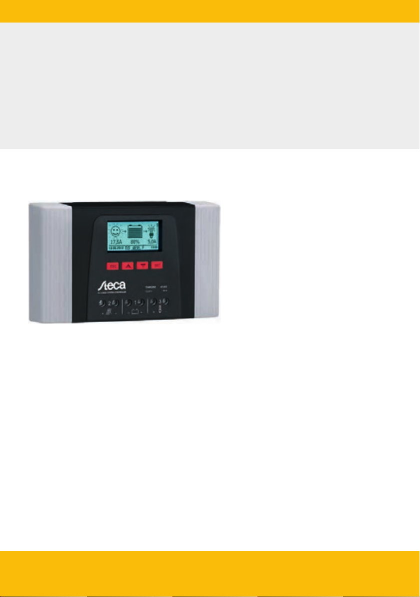
Solarladeregler
Solar Charge Controller
Programmierbar, für Hybrid und Telekommunikations-Systeme
Adjustable, for hybrid and telecommunication systems
Tarom 4545 (12 V/24 V Batterie/accumulator)
Tarom 4545-48 (12 V/24 V/48 V Batterie/accumulator)
Installations- und Bedienungsanleitung
Installation and operating instructions
DE GB
745.487 | Z01.1 | 2013-05-23
Page 2

GB
Table of contents
1 General safety instructions.................................................................................................... 80
2 Identification........................................................................................................................ 81
3 Scope of delivery................................................................................................................... 82
4 Proper usage......................................................................................................................... 83
5 Markings............................................................................................................................... 84
5.1 Symbols for warnings and notices............................................................................... 84
5.2 Keywords..................................................................................................................... 84
6 Quick guide.......................................................................................................................... 85
7 Overview of the controller.................................................................................................... 86
8 Menu structure..................................................................................................................... 88
9 Installation............................................................................................................................ 89
Safety instructions........................................................................................................ 90
9.1
9.2 Connections and operating buttons............................................................................. 91
9.2.1 RJ45 socket for Master bus (⑥ in Fig. 1).................................................................. 91
9.2.2 RJ45 socket for Slave bus (⑤ in Fig. 1)..................................................................... 91
Slot for microSD card (④ in Fig. 1)........................................................................... 92
9.2.3
9.2.4
Relay outputs AUX 1, AUX 2 (
9.2.5 Temperature sensor connection TEMP (⑧ in Fig. 1)................................................. 93
9.2.6 Open UART interface, 3,3 V (⑦ in Fig. 1)................................................................. 93
9.2.7 Function ground (➑ in Fig. 1)................................................................................... 93
9.2.8 Operating buttons.................................................................................................... 94
9.3 Removing/installing the cover...................................................................................... 95
9.3.1 Removing the cover.................................................................................................. 95
9.3.2 Installing the cover.................................................................................................... 95
9.4 Installing the device..................................................................................................... 96
9.5 Establishing the electrical connections......................................................................... 97
9.5.1 Preparing the cables.................................................................................................. 98
9.5.2 Connecting the battery and switching on the controller........................................... 98
9.5.3 Connecting the solar module.................................................................................... 99
9.5.4 Connecting loads.................................................................................................... 100
9.5.5 Connecting optional components........................................................................... 100
9.6 Performing initial commissioning............................................................................... 102
10 Performing initial commissioning....................................................................................... 103
10.1 Overview.................................................................................................................. 103
10.2 Performing initial commissioning............................................................................. 103
11 Dismounting the controller................................................................................................. 107
12 System functions................................................................................................................ 109
12.1 Protection functions................................................................................................. 109
12.1.1
Controller overload............................................................................................... 109
⑨, ⑩ in Fig. 1).......................................................... 92
745.487
77
Page 3

GB
12.1.2 Overheating of the controller................................................................................ 109
12.1.3 Deep discharging of the battery............................................................................ 109
12.2 Control mode........................................................................................................... 109
12.3 Battery charging functions....................................................................................... 110
12.3.1 Float charging....................................................................................................... 110
12.3.2 Boost charging...................................................................................................... 110
12.3.3 Equalise charging.................................................................................................. 111
12.4 Data logger.............................................................................................................. 112
13 Display (layout, function, operation)................................................................................... 113
13.1 Overview (menu structure)....................................................................................... 113
13.2 Status display........................................................................................................... 113
13.3 Display of special states........................................................................................... 115
13.4 General operation ................................................................................................... 115
13.5 Advanced operation................................................................................................. 116
14 Control functions................................................................................................................ 118
14.1 Overview.................................................................................................................. 118
14.2 Operation................................................................................................................. 118
14.3 Functionality............................................................................................................ 121
14.3.1 Deep discharge protection.................................................................................... 121
14.3.2 Morning light function.......................................................................................... 122
14.3.3 Evening light function........................................................................................... 122
14.3.4 Night light function.............................................................................................. 123
14.3.5 Excess energy control............................................................................................ 123
14.3.6 Generator manager............................................................................................... 124
14.3.7 Alarm.................................................................................................................... 125
14.3.8 Timer 1 ... 4........................................................................................................... 125
15 Troubleshooting................................................................................................................. 126
15.1 Event messages........................................................................................................ 126
15.2 Errors without event messages................................................................................ 130
15.3 Self test.................................................................................................................... 132
16 Maintenance....................................................................................................................... 133
16.1 Controller................................................................................................................. 133
16.1.1 Removing dust...................................................................................................... 133
16.1.2 Removing heavy soiling......................................................................................... 133
16.1.3 Checking the charging functionality...................................................................... 134
16.2 System..................................................................................................................... 134
17 Disposal.............................................................................................................................. 135
18 Technical data..................................................................................................................... 136
18.1 Controller................................................................................................................. 136
18.2 Connection cables.................................................................................................... 138
Protocol of the open UART interface........................................................................ 139
18.3
18.3.1 Settings................................................................................................................. 139
78
745.487
Page 4

GB
18.3.2 Data...................................................................................................................... 139
19 Exclusion of liability............................................................................................................ 143
20 Commercial and legal guarantee conditions....................................................................... 144
21 Contact............................................................................................................................... 147
22 Notes.................................................................................................................................. 148
745.487
79
Page 5

GB
1 General safety instructions
n This document is part of the product.
n Only technical professionals may perform the work described in this manual.
n Install and use the device only after reading and understanding this document.
n Always perform the measures described in this document in the sequence specified.
n Keep this document in a safe place for the entire service life of the device. Pass the document
on to subsequent owners and operators of the device.
n Incorrect operation can reduce solar system yields or damage system components.
n The device must not be connected to the DC cables if it has a damaged casing.
n If one of the following components is damaged immediately take the device out of operation
and disconnect it from the battery and modules.
–
Device (not functioning, visible damage, smoke, penetration of liquid etc.),
– Connected cables,
– Solar module.
Do not switch the system on again before
– the device has been repaired by a dealer or the manufacturer,
– damaged cables or solar modules have been repaired by a technical specialist.
n Battery acid splashes on skin or clothing should be immediately treated with soap suds and
rinsed with plenty of water. Immediately seek medical advice in the case of injuries.
n If battery acid splashes into the eyes, immediately rinse with plenty of water and seek medical
advice.
n Never cover the device.
n Do not open the casing: Risk of death. Invalidation of the guarantee.
n Factory labels and markings must never be altered, removed or rendered unreadable.
n Observe the manufacturer's manual when connecting an external device that is not described in
this document. Incorrectly connected devices can damage the controller.
n This device is not intended for
– children,
– persons with physical, sensory or mental impairment,
– persons without sufficient experience or knowledge unless they are instructed in the use of
the device, and initially supervised, by a person responsible for their safety.
80
745.487
Page 6

2 Identification
General information
Feature Description
Type Tarom 4545, Tarom 4545–48
Issue version of the manual Z01
Manufacturer's address
Optional accessories
Display
The controller indicates the version of the manual matching the software under
‘Information’
▶
‘System info’
Ä Contact, p. 147
see
.
n External temperature sensor Steca PA TS-S
n Device-specific Steca current sensor
n Termination plug
‘Main menu’
GB
▶
745.487
81
Page 7

GB
3 Scope of delivery
n Tarom 4545 or Tarom 4545–48
n Operating instructions
82
745.487
Page 8

4 Proper usage
The solar charge controller, hereinafter named as the
alone photovoltaic systems for charging and controlling a lead-acid battery containing liquid or gel
electrolyte. The following applies in addition:
n The controller must not be connected to the public power grid.
n Only solar modules may be connected to the solar module connection.
n Depending on the battery used, the connected loads must be suitable for use with one of the
following voltages:
Tarom 4545: 12 VDC, 24 VDC
Tarom 4545–48: 12 VDC, 24 VDC, 48 VDC
n The controller performs the following tasks:
– Monitoring of the battery charging process
– Controlling of the charging process, protection of the battery from overcharging
– Switching loads on and off, protection of the battery from deep discharge
controller
or
device
, may only be used in stand-
GB
745.487
83
Page 9

GB
5 Markings
5.1 Symbols for warnings and notices
Symbol Description Location
general danger warning Manual
Danger from electricity Manual
Read the manual before using the product. Device
Danger from hot surfaces Manual, Device
5.2 Keywords
The following symbols are used in conjunction with the symbols from
Keyword Description
Danger immediate danger of death or serious bodily injury
Warning possible danger of death or serious bodily injury
Caution possible danger of light or medium bodily injury
Notice possible damage to property
Note Note on operation of the device or use of the manual
Ä 5.1
.
84
745.487
Page 10
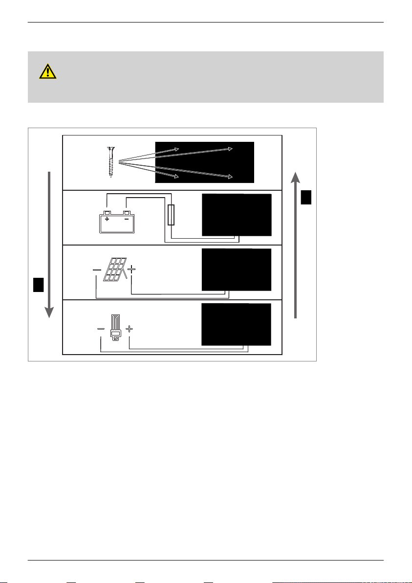
6 Quick guide
4 x
1.
2.
3.
4.
Installation
Deinstallation
DANGER!
Risk of death by electrocution. Observe the safety instructions in
Ä 9.1, p. 90
GB
et seqq.
745.487
85
Page 11
1
4
5
6
7
9
10
8
Tarom 4545: max. 60 V
peak
Tarom 4545–48: max. 100 V
peak
M+
M+
M–
B+
B– L+ L–
M–B+B–L+L–
Tarom 4545: 12/24 V
Tarom 4545–48: 12/24/48 V
2
3 5
6
7
4
2 1 3
8
GB
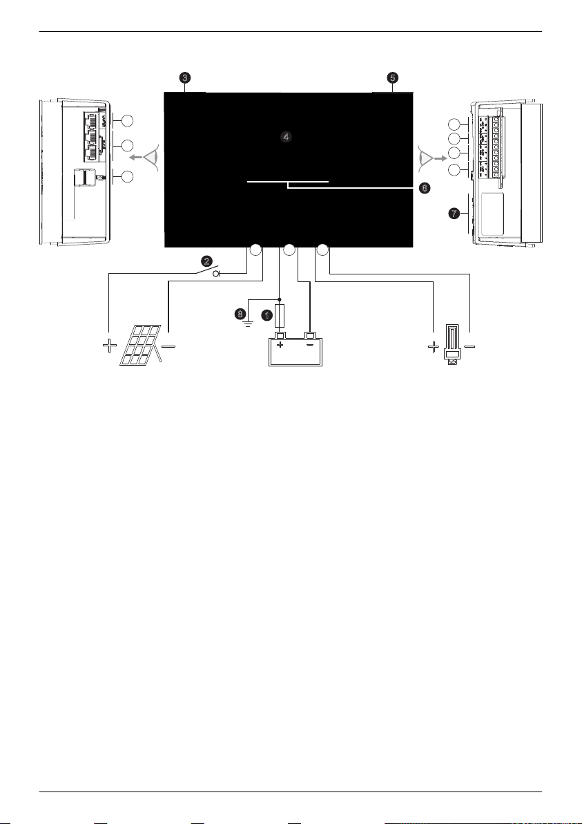
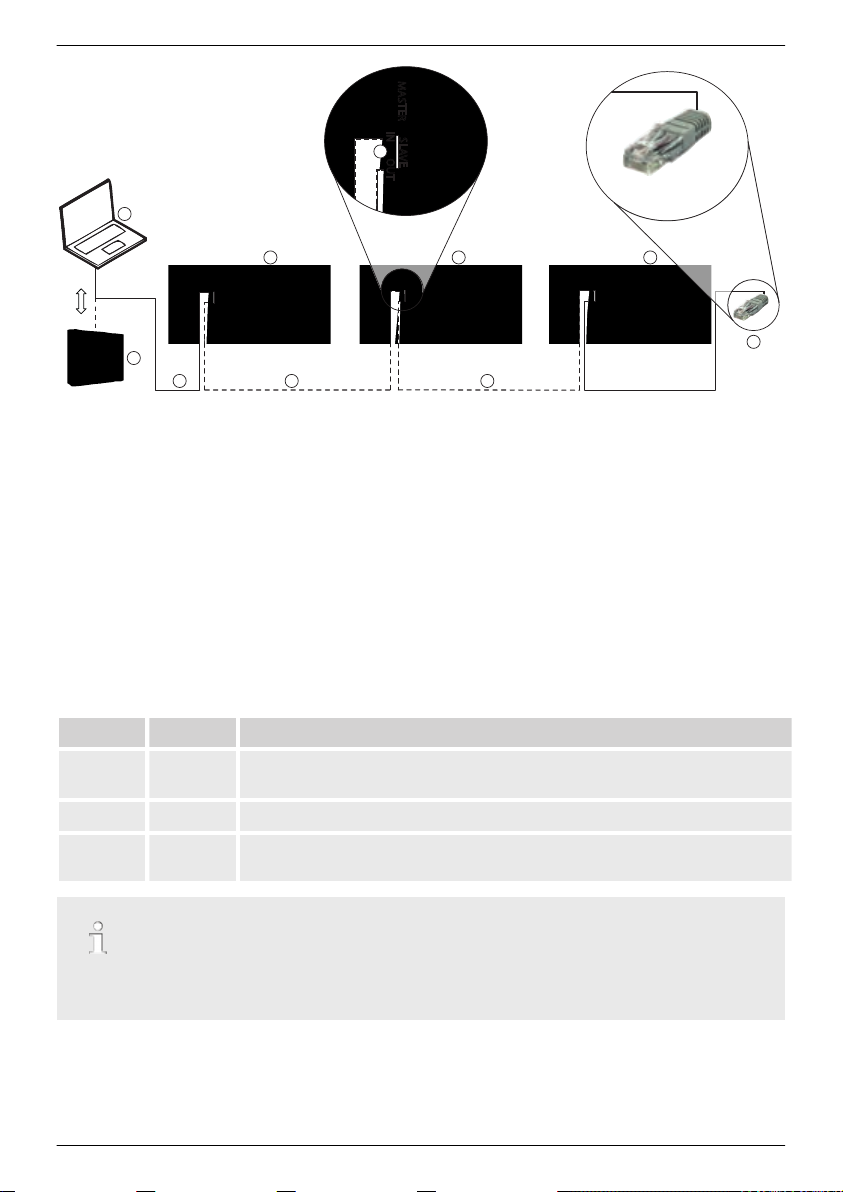
7 Overview of the controller
Fig. 1: Overview of casing and connections
Connections Other components
①
Battery connection: terminals 1+ and 1−
②
Solar module connection: terminals 2+ and
➊External battery fuse (safety fuse or DC line
circuit breaker 1)
➋
DC load circuit breaker 1)
2−
③
④
⑤
Load output for connecting the loads: terminals 3+ and 3−
Micro SD slot for microSD card
SLAVE IN and SLAVE OUT RJ45 sockets
➌Left cover
➍Display
➎Right cover
for RS485 Slave bus
⑥
MASTER RJ45 socket for RS485 Master bus
⑦
Open UART interface, 3.3 V
⑧
Temperature sensor connection TEMP for
Steca PA TS-S
⑨
AUX 2 relay output
86
➏
ESC, r, s, SET operating buttons
➐Type plate
➑Positive ground, optional
2)
2)
745.487
Page 12

⑩
AUX 1 relay output
1)
Technical data at
2)
Optional, not included in delivery
Ä 18.1, p. 136
GB
.
745.487
87
Page 13

SET SET SET
SET SET
1)
SET SET SET
1)
SET SET SET SET
SET
SET
SET SET SET
SET SET
SET
SET
SET
SET
1)
2)
4)
SET
5)
7)
3) Submenus: Operation mode, cycle
Device
temperature
Remaining
capacity
Cable
compensation
Expert menu
Same menus as with load but also with alarm
AUX1 and AUX2 only
Factory
reset
6) Submenus: On/Off, temp. coefficient
Submenus: Contact details, system info
Temp.
compensation
Submenus for displaying the stored energy/current values
Submenus: Float charging, boost charging, equal. charging
Equal. charge
dur.
Temperature
sensor
Battery current
Load current
Daily input
device
Daily load device
Self test
Information 4)
Date
Operation
mode
Night light
Boost charge
dur.
Contrast
RS485 slave
addr.
UART/RS232
open
Timer 1
Excess energy
contr.
Morning light
Alarm 7)
Deep discharge
protection
Select function
Evening light
Generator
manager
Clear log data
Clear
event log
Equal.
charge
6)
State of charge
Time
Language
Timer 4
Start boost
charge
Battery
capacity
Charge
voltages
Function
settings
5)
System voltage
Status display Main menu
Basic setting
Battery
voltage
Output settings
Internal data
logger 2)
System
settings
Submenus
Load
AUX 1
AUX 2
Time format
Date format
Input current
Battery settingsPV current
Event
log
3)
Control mode
Battery type
Time/date
GB
8 Menu structure
For the sake of clarity, only the s and
‘SET’
operating buttons are illustrated.
88
745.487
Page 14

9 Installation
The following section describes only the installation of the controller. Observe the respective
manufacturer's manual when connecting external components (solar module, battery, load, sensors).
Topics
1. Safety instructions
2.
Ä Connections and operating buttons, p. 91
3.
Ä Removing/installing the cover, p. 95
4.
Ä Installing the device, p. 96
5.
Ä Establishing the electrical connections, p. 97
GB
745.487
89
Page 15

GB
9.1 Safety instructions
DANGER!
Risk of death by electrocution! Observe the following safety instructions when performing the
measures described in the installation section.
General information
Only technical professionals may perform the work described in the 'installation' section.
–
– Do not open the controller case.
– All covers must be installed during operation.
– Always take the following measures before working on the controller:
1. Switch off all loads.
2. If present, switch off the DC load circuit breaker (solar module) and secure it against
being switched on again or safely cover the solar module (wind).
3. Switch off the external battery fuse: Remove the fuse insert from the fuse holder (safety
fuse) or switch off the DC line circuit breaker and secure it against being switched on
again.
4. Disconnect the battery cable from both battery terminals.
Cable connections
– The module cables carry voltage when the solar module is illuminated.
– Insulate exposed cable ends with insulation tape or wire connector blocks.
–
Connect the cables for the battery, solar module and loads to the controller in the
described sequence.
– Secure the cables with a strain relief clamp. Clearance of strain-relief to controller: 200 mm.
– Connect only 1 cable to each connection terminal.
– Cables used: Observe the specifications in the Technical data section.
– Lay the cables so that
– connections cannot accidentally come loose,
– persons cannot tread on or trip over these,
– fire protection devices must not be impaired.
– The entire installation must be designed with Protection Class II if the open-circuit module
voltage exceeds 60 V DC at least once anywhere over the entire temperature range.
– Observe all applicable installation regulations and standards, national laws and connection
values specified by the regional power supply company.
Fuses and switching devices
Installation of an external battery fuse (line fuse or DC line circuit breaker) is mandatory.
Observe the following:
– Mount the external battery fuse directly next to the battery.
– The external battery fuse must conform to the specifications in the technical data section
– The external battery fuse is not included in the scope of delivery.
90
745.487
Page 16
WARNING!
Danger of acid injuries.
– Do not subject the battery to open flames or sparks.
– Provide adequate ventilation in the installation location of the battery. Inflammable gases
can escape from the battery.
– Follow the charging instructions of the battery manufacturer.
ATTENTION!
Danger of destroying the device through overloading
– Conform to the technical specifications, especially the connection values. See the type plate
– When selecting the solar module, note that the open-circuit module voltage is higher than
– Connect only 1 controller to each solar module.
– Tighten the connection terminals as shown: Battery, solar module and loads with
Ä 18, p. 136
and
the value specified on the type plate at temperatures below 25 °C.
2.5 ... 4.5 Nm
et seqq.
GB
9.2 Connections and operating buttons
The following section describes the connections and operating buttons. For information on the display and operation see
9.2.1 RJ45 socket for Master bus (⑥ in Fig. 1)
For future functions.
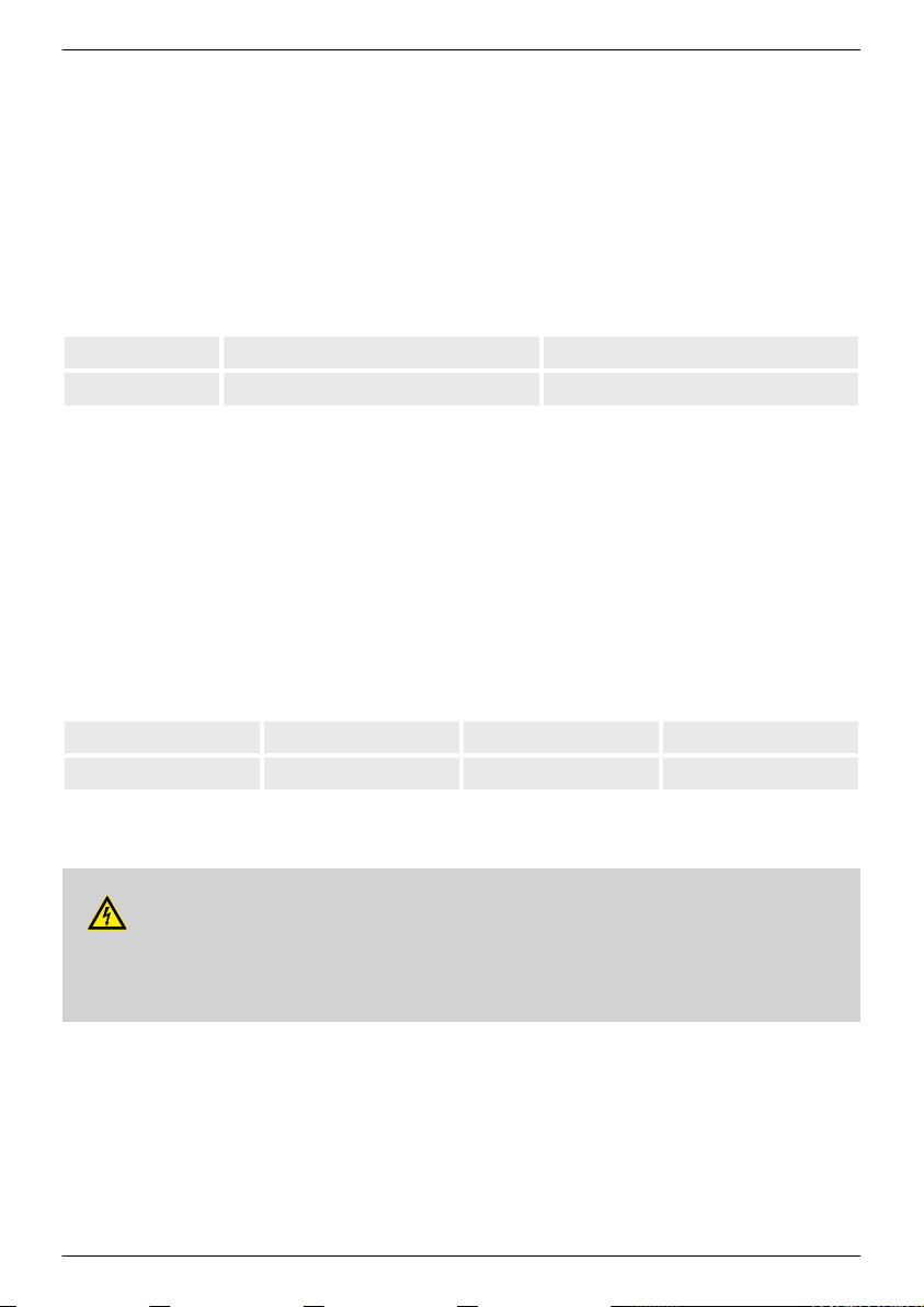
9.2.2 RJ45 socket for Slave bus (⑤ in Fig. 1)
The controller is one of a maximum of 31 Slaves on the Slave bus. The following applies in addition:
n Multiple controllers can be connected.
n Only 1 Master may be connected ① (Fig. 2
Steca Master device suitable for use in stand-alone systems.
n Each Slave ②, ③, ④
addresses must not be present. Set the Slave address of the controller under
‘System settings’
n The Master at one end of the bus and the last Slave at the other end must be terminated ⑦; see
Master/Slave instructions.
n Bus cable ⑥: Standard RJ45 cable (Cat-5 Patch cable, 1:1, not supplied, for length see
n For pin assignments of the RJ45 socket: see table in
745.487
Ä 13, p. 113
must have its own unique address within a range of 1 to 99; duplicate
.
). Possible Masters: PC or data logger or another
‘Main menu’
▶
‘RS485 slave addr.’
.
Ä 9.2.1
.
▶
Ä 18.2
).
91
Page 17
MASTER
SLAVE
IN OUT
MASTER
SLAVE
IN OUT
MASTER
SLAVE
IN OUT
MASTER
SLAVE
IN OUT
RJ45
RS485 RS485 RS485
1
2 3
5
4
1
6 66
7
GB
Fig. 2: Wiring the Slave bus
9.2.3 Slot for microSD card (④ in Fig. 1)
For future functions.
9.2.4 Relay outputs AUX 1, AUX 2 (⑨, ⑩ in Fig. 1)
The relay outputs can be used for switching devices or loads (loads via an external power relay).
Devices connected to the relay outputs are controlled via the control functions provided by the controller. Relay output pin assignments:
AUX 1 AUX 2 Description
1 (NC) 4 (NC)
Normally closed
relay contact; the contact is closed when the relay is
switched off.
2 (COM) 5 (COM)
3 (NO) 6 (NO)
Common relay contact
Normally open
relay contact; the contact is open when the relay is
switched off.
Heavy loads directly connected to the battery can be switched using an additional power relay
connected to the AUX 1 or AUX 2 outputs, e.g. via the Steca PA EV 200 A.
Related topics:
92
745.487
Page 18
n
Ä Connecting optional components, p. 100
n
Ä Control functions, p. 118
n Technical data for the relay outputs at
Ä 18.1, p. 136
9.2.5 Temperature sensor connection TEMP (⑧ in Fig. 1)
If the controller and battery are not located in the same room then an external temperature sensor
for measuring the battery temperature must be installed. We recommend using the optionally available Steca PA TS-S. Pin assignments:
GB
Pin
Signal
1)
Any polarity can be used.
Related topics:
7 (EXT.) 8 (GND)
Sensor connection
Ä Control mode, p. 109
1)
.
Sensor connection
1)
9.2.6 Open UART interface, 3,3 V (⑦ in Fig. 1)
The open UART outputs the current and voltage values of the loads, battery, solar module and other
values measured by the controller. The interface can be switched on and off.
Interface protocol: see
Ä 18.3, p. 139
.
Pin assignments:
Pin
9 (GND) 10 (TX) 11 (RX)
Signal Ground TX RX
9.2.7 Function ground (➑ in Fig. 1)
DANGER!
Risk of death by electrocution.. Grounding causes the system to leave the safety extra-low
voltage range. Protection against directly touching live components must be restored via appropriate isolation measures.
745.487
93
Page 19

GB
ATTENTION!
– The system voltage of thin-film modules must be positive to avoid corrosion. This require-
not
ment is satisfied in stand-alone systems that are
grounded.
– Danger of damaging the devices (e.g. computer) connected to the Master/Slave bus or the
UART interface.
All
bus connections must be galvanically isolated when the system is
grounded.
The controller does not need to be grounded in stand-alone systems. We recommend not
grounding the controller. Also observe the local regulations.
If required, the controller can be grounded via the positive battery terminal
‘1+’
of the controller.
Observe the following:
n The connection point must lie between the external battery fuse and the controller.
n The connection point can be used as a common ground for all system components.
n Take the grounding of the entire system into account.
9.2.8 Operating buttons
The operating buttons have the following functions:
Button Function
SET
ESC
r/s n moves the selection bar or the display content upwards/downwards
n jumps down by one menu level
n changes the state of a control element (check box/radio button)
n causes the selected numeral to blink so that it can be modified
n answers a query dialog with
Yes
n adopts a change
n jumps up by one menu level
n jumps to the status display (press for 1 s)
n answers a query dialog with
No
n discards any changes
n moves the selection 1 position to the left/right on a settings page
n increases/reduces the setting value by 1 step
n repeated button presses: press button for a longer time
94
745.487
Page 20
9.3 Removing/installing the cover
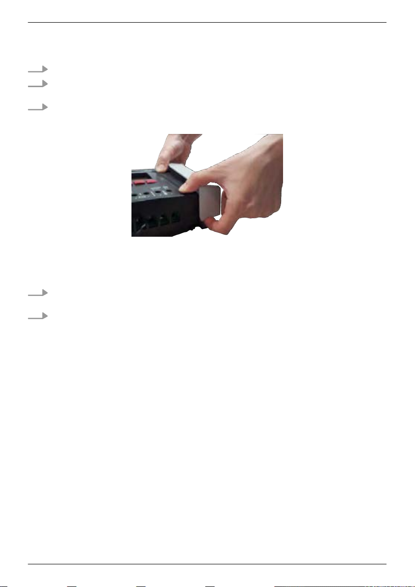
9.3.1 Removing the cover
1. Grip the cover with both hands as shown in Fig. 3.
2. Use your index fingers to pull the edges slightly outwards and then pull upwards so that the
cover is released from the end position.
3. Pull off the cover entirely by lifting it upwards.
Fig. 3: Release the cover from the end position (here the right cover)
9.3.2 Installing the cover
1. Position the cover on the casing so that the two guide lugs on the cover fit into the guide
slots in the casing.
2. Slide the cover onto the casing until it audibly latches into place.
GB
745.487
95
Page 21
GB
9.4 Installing the device
ATTENTION!
Danger of damage to the inverter and reduction of power. Observe the following safety requirements during installation:
– The mounting location and immediate environment are permanently fixed, vertical, flat,
non-inflammable and not subject to constant vibration.
A free space of at least 60 mm must be present on all sides of the controller. The required
–
free space relates to the controller
– The controller must be easily accessible and the display easily readable.
– The controller is mounted as close as possible to the battery; the prescribed minimum
safety clearance of 0.5 m between the controller and battery is adhered to.
– The controller must not be located
– outdoors or in a location subject to rain or splashing water,
– in dusty environments,
– in areas with active animal husbandry,
– in direct sunlight.
– The battery cable is no longer than 2 m (recommended), to keep cable losses and compen-
sating voltage as low as possible.
– Do not drill through the fastening openings ① (Fig. 4).
1. Select the mounting location under consideration of the previously mentioned safety requirements.
2. Remove both controller covers.
3. Position the controller level on the mounting surface and mark the mounting holes through
the fastening openings ①.
4. Remove the controller and drill the mounting holes.
5. Use 4 suitable screws (max. M5) to fasten the controller to the mounting surface.
without
covers; see ② in Fig. 4.
96
745.487
Page 22
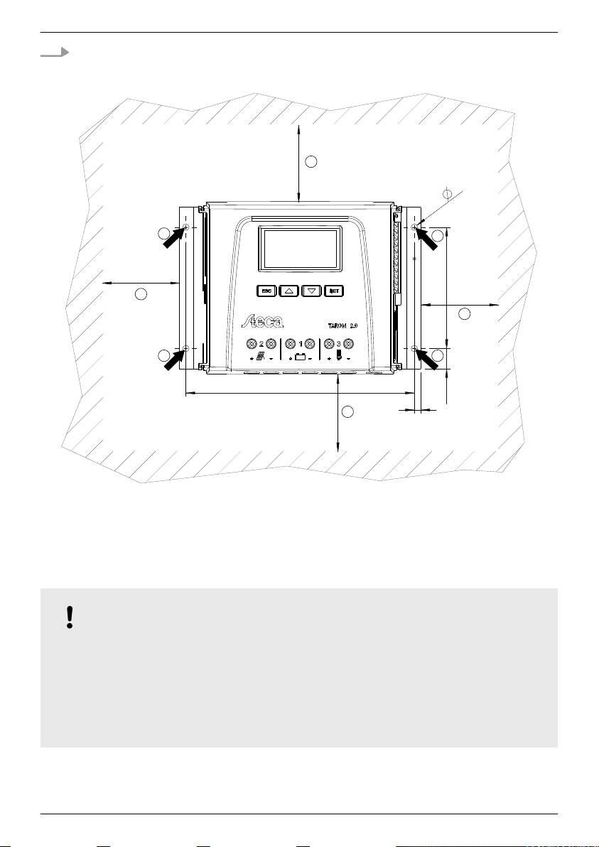
6. Install the covers.
177
94
5
15.5
4x
5
60
60
60
60
1
2
2
2
2
1 1
1
GB
Fig. 4: Fastening openings ① and free space ②
9.5 Establishing the electrical connections
Always make connections in the following sequence:
ATTENTION!
Always make connections in the following sequence:
1. First connect the load and then the source.
Example
: First connect the cable to the controller and then to the battery.
2. Connect the positive pole first then the negative pole.
Example
745.487
: First connect B+ then B–.
97
Page 23
GB
9.5.1 Preparing the cables
1. Label the cable ends as per Fig. 1, p. 86 (M+, M–, B+, ...).
2. Lay the battery, module and load cables directly next to each other. Do not yet connect the
cables!
3. Connect the external battery fuse, close to the battery and easily accessible, to the battery
cable B+ (➊ in Fig. 1).
4. Switch off the external battery fuse: Remove the fuse insert from the fuse holder (safety fuse)
or switch off the DC line circuit breaker and secure it against being switched on again.
5. Connect the optional DC load circuit breaker, close to the controller and easily accessible, to
the module cable M+ (➋ in Fig. 1).
6. Switch off the DC load circuit breaker and secure it against being switched on again.
9.5.2 Connecting the battery and switching on the controller
✔
No devices are connected to the battery.
1.
ATTENTION!
Danger of damage to the controller. Observe the maximum battery voltage as per
Ä 18.1, p. 136
.
Connect the battery cable and external battery fuse to the battery connection of the controller and to the battery.
2. Switch on the external battery fuse: Insert the fuse insert into the fuse holder (safety fuse) or
switch on the DC line circuit breaker . The controller automatically starts operation and, after
a few seconds, displays the detected system voltage (= battery voltage) in an event message
(Fig. 5).
3. Note the system voltage displayed in Fig. 5.
‘ESC’
4. Press
5. Confirm other event messages with
6. If Fig. 5 and Fig. 6 are not displayed then check the installation and if necessary correct the
error using
7. Check that the noted system voltage corresponds to the actual battery voltage. If not, set the
system voltage in the expert menu (
‘System voltage’
98
to confirm the event message. The basic setting display appears (Fig. 6).
‘ESC’
, e.g.
Ä 15, p. 126
et seqq.
‘Main menu’
; more information on this is provided in
‘RTC not set’
▶
‘Battery settings’
.
▶
Ä 13.5, p. 116
‘Expert menu’
).
▶
745.487
Page 24
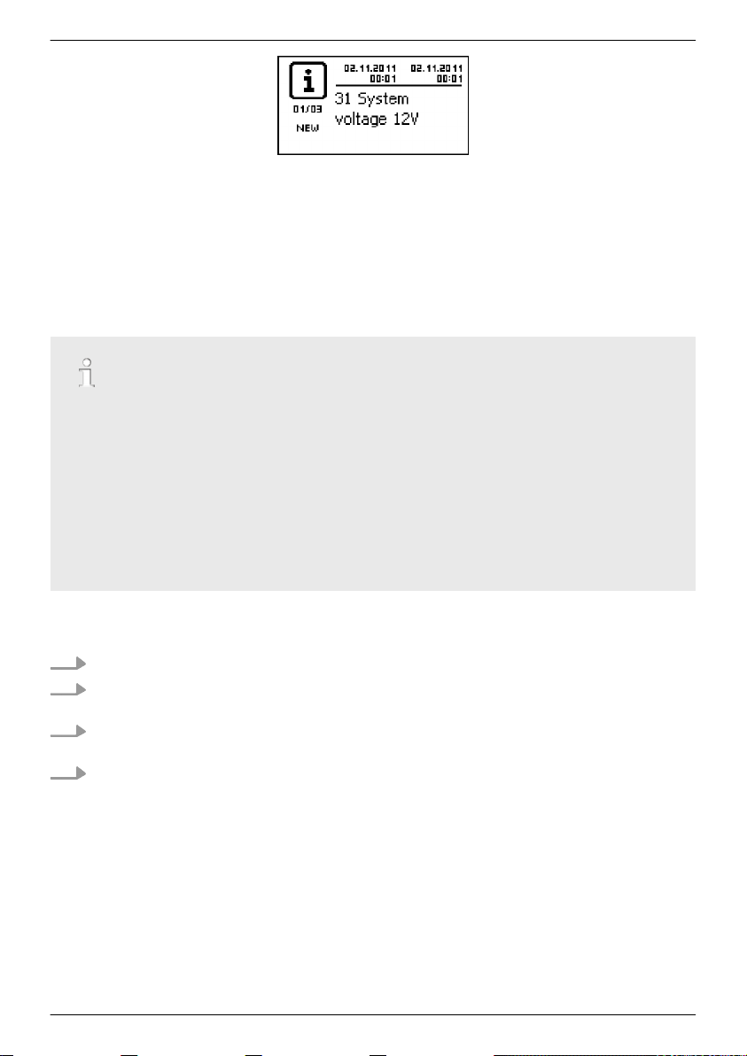
Fig. 5: Event message with the detected system voltage (in the example: 12 V)
Fig. 6: Basic setting of the status display
The battery can be charged from multiple sources. The following applies:
–
The battery can be charged by up to 5 controllers connected to the battery in parallel.
–
Apart from the controller, other suitable charging sources can also be connected to the
battery. These charging sources can be switched on and off by the controller via the
‘AUX 1’ and ‘AUX 2’ relay outputs.
–
The controller can only determine the charge state of the battery when the charge current
of the other controllers and other charging sources is measured using a device-specific
Steca current sensor.
–
We recommend having the connection of additional controllers and other charging sources
planned by a technical expert.
GB
9.5.3 Connecting the solar module
1. Safely cover the module (wind)
2. Connect the module cable and optional DC load circuit breaker to the solar module connection of the controller and to the solar module.
3. Remove covers from the solar module and, if present, switch on the DC load circuit breaker.
The display shows Fig. 7 or Fig. 8.
4. If Fig. 7/Fig. 8 is not displayed then check the installation and if necessary correct the error
Fig. 7: Display with sunshine after connecting the solar module
745.487
Ä 15, p. 126
using
et seqq.
99
Page 25

1
2
GB
Fig. 8: Display without sunshine after connecting the solar module
9.5.4 Connecting loads
ATTENTION!
– Danger of destroying the controller through overloading.
– Loads that consume more current than can be supplied by the controller must be
directly
connected to the battery!
– Always directly connect inverters to the battery!
– Danger of battery destruction due to deep discharging. Consumers that are not allowed to
be switched off by the deep discharge protection of the controller (emergency lighting,
radio link) must be directly connected to the battery and must not deeply discharge the
battery.
– Danger of battery and cable destruction due to overloading. Directly connected loads must
be separately fused.
1.
Switch off the load output (
2. Connect the load cable to the loads and to the load output of the controller.
3. Switch on the load output. The lamp ① (Fig. 9) appears on the display.
4. Switch on the load. Load currents ② greater than 0.1 A are shown on the display.
5. If Fig. 9 is not displayed then check the installation and if necessary correct the error using
Ä 15, p. 126
et seqq.
Ä Switching loads on/off (load output), p. 116
).
Fig. 9: Display content after connecting the load
9.5.5 Connecting optional components
Connecting the positive ground
Connect the ground to the positive battery terminal
100
‘1+’
(observe
Ä 9.2.7, p. 93
).
745.487
Page 26

Installing lightning protection
Install suitable lightning protection.
Connecting relay outputs 1 and 2
ATTENTION!
Danger of destruction of the relays. Observe the technical data of the relays (
Ä p. 136
et
seqq.)!
‘AUX 1’
and
‘AUX 2’
1. Connect external components to the relay outputs
2.
Configure the relay outputs as per
Ä 14, p. 118
et seqq.
.
Connecting the external temperature sensor Steca PA TS-S
1. Install the temperature sensor Steca PA TS-S near to the battery.
2. Connect the sensor cable to contacts 7 (
3. Set the temperature sensor under
to
‘external’
.
‘EXT.’
‘Main menu’
) and 8 (
‘GND’
▶
‘Battery settings’
) (any polarity).
▶
‘Temperature sensor’
Master bus: connecting a Steca current sensor and other Slave devices
1. Set the addresses of the optionally available device-specific Steca current sensor and other
suitable Slave devices (observe the instructions in
Ä 9.2.1, p. 91
).
GB
Maximum length of the Master bus cable: see Ä 18.2).
2. Connect the Slave devices to the Master bus.
3. Connect the Master bus to the
‘MASTER’
RJ45 socket.
4. Terminate the last Slave device according to the manufacturer's instructions.
745.487
101
Page 27

GB
Slave bus: connecting the Master and Slave devices
1.
Set the addresses of the Master and Slave devices (observe the instructions in
91
).
Maximum length of the Master bus cable: see Ä 18.2).
2. Connect the Master and Slave devices to the Slave bus.
3. Connect the Slave bus to the
4. Terminate the last Slave device according to the manufacturer's instructions.
Controller: plug the optionally available termination plug Steca PA RS485-TERM into the free
‘SLAVE IN’
Connecting the open UART interface
Connect external devices to the open UART interface (observe the instructions in
93
Installing cable strain relief
Secure the cables with a strain relief clamp. Clearance to controller: 200 mm.
/
‘SLAVE OUT’
).
‘SLAVE IN’
socket on the last controller.
and
‘SLAVE OUT’
RJ45 sockets.
Ä 9.2.2, p.
Ä 9.2.6, p.
9.6 Performing initial commissioning
Perform initial commissioning as per
102
Ä 10, p. 103
.
745.487
Page 28

10 Performing initial commissioning
ATTENTION!
Danger of damage to the device and reduction of power. Only technical professionals may perform the work described in this section.
10.1 Overview
Initial commissioning includes the following steps:
1. Show the basic setting of the status display
2. Set the language
3. Set the time and date
4. Set the battery type and capacity
5. Set the control type
6. Switch off cable compensation (only if required)
10.2 Performing initial commissioning
✔
All the measures described in
completed.
Ä 9.4
and
Ä 9.5
have been
GB
Showing the basic setting of the status display
If necessary, press
u
the status display.
Setting the language
1. Press
‘SET’
settings’
Note
English
2.
Press s twice to select
745.487
‘ESC’
for 1 s to show the basic setting of
. The main menu appears and the
entry is selected (Fig. left).
is set as the default menu language at the factory.
‘System settings’
‘Output
.
103
Page 29

GB
3. Press
‘Language’
‘SET’
. The
‘System settings’
is selected (Fig. left).
menu appears and
Setting the time
Setting the date
4. Press
5.
6. Press
1. Press
2.
3. Press
4. Press
5. Press
6.
7. Press
8.
9. Repeat steps 5 to 7 for setting the minutes.
‘SET’
. The
‘Language’
Press r s to select a different language.
‘SET’
.
‘ESC’
. The
‘System settings’
Press s to select
‘SET’
selected.
‘SET’
‘SET’
Press rs to change the hour.
‘SET’
Press s. The minutes are selected.
‘Time/date’
. The
‘Time/date’
. The
‘Time’
. The hour flashes.
. The hour stops flashing.
menu appears (Fig. left).
menu appears (Fig. left).
.
menu appears and
dialog appears (Fig. left).
‘Time’
is
104
1. Press
2.
3. Press
4. Press
5.
6. Press
7.
8. Repeat steps 4 to 6 for setting the month.
‘ESC’
. The
‘Time/date’
‘Date’
Press s to select
‘SET’
. The
‘SET’
. The day flashes.
Press sr to change the day.
‘SET’
. The day stops flashing.
Press s to select the month.
.
‘Date’
dialog appears (Fig. left).
menu appears.
745.487
Page 30

Setting the battery type
9.
Press s to select the year.
10. Repeat steps 4 to 6 for setting the year.
GB
1. Press
2. Press
3.
4. Press
5.
Setting the battery capacity
1. Press
2.
Press s to select
Press s to select
6. Press
7.
Press sr to select a different battery type.
8. Press
Press s to select
3. Press
4. Press
5.
Press sr to change the value.
6. Press
‘ESC’
for 1 s. The basic setting display appears.
‘SET’
. The main menu appears.
‘Battery settings’
‘SET’
. The
‘Battery settings’
‘Battery type’
‘SET’
. The
‘Battery type’
‘SET’
. The selected battery type is set.
‘ESC’
. The
‘Battery settings’
‘Battery capacity’
‘SET’
. The
‘Battery capacity’
‘SET’
. The value flashes.
‘SET’
. The value stops flashing.
.
menu appears.
.
dialog appears (Fig. left).
menu appears.
.
dialog appears (Fig. left).
Setting the control mode
Note
The control mode
and only needs to be changed if required. More information on
this is provided in
1. Press
2.
745.487
Press r to select
‘State of charge (SOC)’
Ä 12.2, p. 109
‘ESC’
. The
‘Battery settings’
‘Control mode’
is preset at the factory
.
menu appears.
.
105
Page 31

GB
3. Press
‘SET’
. The
‘Control mode’
dialog appears (Fig. left).
Switching off cable compensation
Finishing initial commissioning
4.
Press sr to select
5. Press
‘SET’
. The voltage control is set.
‘Voltage control’
.
Note
Cable compensation is switched on at the factory and only needs
to be switched off if required. More information on this is provided
Ä 12.2, p. 109
in
1. Press
2.
Press sr to select
3. Press SET. The
4.
Press sr to select
5. Press
Press
u
et seq.
‘ESC’
. The
‘Battery settings’
‘Cable compensation’
‘Cable compensation’
‘Off’
.
‘SET’
. Cable compensation is switched off (Fig. left).
‘ESC’
for 1 s. The basic setting of the status display
menu appears.
.
dialog appears.
appears and initial commissioning is finished.
Note
You can usually now use the controller without making any further
settings. For information on important additional functions see
Ä 14, p. 118
et seqq.
106
745.487
Page 32

11 Dismounting the controller
DANGER!
Risk of death by electrocution.. Only technical professionals may perform the work described in
this section. Observe the warning notes in
WARNING!
Danger from hot surfaces. Allow the heatsink on the rear of the device to cool down before
touching.
Disconnecting the loads from the controller
1. Switch off all loads.
2. Disconnect the load cables L− and L+ from the controller.
Disconnecting the solar module from the controller
Ä 9.1, p. 90
.
GB
3. If present, Switch off the DC load circuit breaker (solar module) and secure it against being
switched on again or Safely cover the module (wind).
4. Disconnect the module cables M− and M+ from the controller and insulate the cable ends.
Disconnecting the battery from the controller
5. Switch off the external battery fuse: Remove the fuse insert from the fuse holder (safety fuse)
or switch off the DC line circuit breaker and secure it against being switched on again.
6. Disconnect the battery cables B− and B+ from the controller and insulate the cable ends.
Finishing dismounting
745.487
107
Page 33

GB
7. If present, disconnect any remaining components from the controller (buses, sensors etc.).
8. Remove the controller from the mounting surface.
108
745.487
Page 34

12 System functions
12.1 Protection functions
12.1.1 Controller overload
The controller is protected from the following faults and is not damaged when these faults occur
individually
n Solar module
n Solar module
n Solar module
n Battery not connected
Once the individual fault has been corrected the controller will operate correctly without taking any
further measures.
.
or
battery or load connected with the wrong polarity
or
battery or load incorrectly connected
or
load short-circuited
ATTENTION!
damage
The following faults
– At least 2 of the above mentioned faults occur
– The load outputs of multiple controllers are connected in parallel.
– A solar module is connected to multiple controllers in parallel.
the controller:
simultaneously
.
GB
If the battery voltage drops below 10.5 VDC, safe operation of the controller can no longer be
guaranteed. The controller stops all functions, especially charging of the battery.
12.1.2 Overheating of the controller
The cooling fins on the rear side and the internal temperature controller prevent the controller from
overheating. If the controller becomes too hot then the battery is no longer charged and the load
output is also switched off if necessary.
12.1.3 Deep discharging of the battery
To protect the battery from deep discharge the controller switches off the load output and the
‘AUX 1’
and
‘AUX 2’
118
et seqq.
relay outputs if necessary. More information on this is provided in
Ä 14, p.
12.2 Control mode
The controller has 2 control modes:
n Based on the actual state of charge of the battery (SOC control)
n Based on the battery voltage (voltage control)
745.487
109
Page 35

GB
SOC control is highly recommended because this should result in a longer service life of the battery.
When
SOC control
Voltage control
n If components are directly connected to the battery the controller can only determine the SOC
when the battery currents are measured using a device-specific Steca current sensor. If the battery current cannot be measured then the controller must be switched to
n The controller takes the battery temperature into account for accurate determination of the
charge completion voltage. To do this, the controller measures the room temperature using its
own internal temperature sensor and assumes that the battery is also at room temperature. If
the battery is located in a different room then the external temperature sensor Steca PA TS-S
(optional) should be used.
n The voltage drop in the battery cables distorts the battery voltage measurements and thus also
the actual charging voltage present at the battery. The cable compensation of the controller
compensates for this voltage drop after the first full charge. Additional sensors are not required.
Cable compensation is switched on in the factory settings.
Operation
n Control mode:
n Temperature sensor:
n Cable compensation:
is switched on the charge state of the battery is displayed in percent, with
the charge state is displayed in volts. The following applies in addition:
Voltage control
‘Main menu’
▶
‘Battery settings’
‘Main menu’
‘Main menu’
▶
‘Battery settings’
▶
‘Battery settings’
▶
‘Control mode’
▶
‘Temp. sensor’
▶
‘Cable compensation’
.
12.3 Battery charging functions
12.3.1 Float charging
When the battery is fully charged, the controller automatically switches to float charging (charging
with the float charge voltage). This prevents the battery from being discharged.
ATTENTION!
The float charging voltage must be set according to the specifications of the battery manufacturer to ensure optimum charging of the battery.
Operation
Float charging voltage:
12.3.2 Boost charging
Boost charging provides more intensive care of the battery than float charging. The following
applies in addition:
110
‘Main menu’
▶
‘Battery settings’
▶
‘Charge voltages’
▶
‘Float charging’
745.487
Page 36

n Boost charging starts when the switch-on threshold1) is reached. Boost charging can also be
started manually.
n Boost charging stops after the charge duration has expired or when the charge completion
voltage has been reached, whichever happens first.
n With boost charging the charging voltage is higher than with float charging.
n After boost charging the controller automatically switches to float charging.
Observe the manufacturer's specifications when setting the charge duration and charge completion voltage.
Operation
n Switch-on threshold:
charging’
▶
‘Starting threshold’
n Charge duration:
n Charge completion voltage:
charging’
▶
‘End of charge volt.’
n Starting boost charging manually:
‘Main menu’
‘Main menu’
‘Main menu’
▶
‘Battery settings’
▶
‘Battery settings’
▶
‘Main menu’
▶
‘Charge voltages’
▶
‘Expert menu’
‘Battery settings’
▶
‘Battery settings’
2)
‘Boost charge dur.’
▶
▶
‘Charge voltages’
▶
‘Start boost charge’
▶
‘Boost
▶
‘Boost
GB
1)
Value in
2)
More information on this is provided in
116
percent
with SOC control, in
volts
with voltage control
Ä Calling up the expert menu for battery settings, p.
.
12.3.3 Equalise charging
Equalise charging prevents acid layering via controlled gassing and thus extends the service life of
the battery. The following applies in addition:
n Equalise charging starts when the cycle has expired or the switch-on threshold1) is crossed.
n Equalise charging stops after the charge duration has expired or when the switch-off threshold
has been reached, whichever happens first.
n Equalise charging is switched on in the factory settings. Prerequisite: Battery type =
electrolyte’
–
–
.
Observe the manufacturer's specifications when setting the cycle and charge duration.
Equalise charging is only possible when a battery type of ‘Liquid electrolyte’ is set.
‘Liquid
1)
745.487
111
Page 37

GB
Operation
n Generally switching equalise charging on/off:
charging’
n Cycle:
n Switch-on threshold:
charging’
n Switch-off threshold:
charging’
n Battery type:
n Charge duration:
▶
‘Operation mode’
‘Main menu’
▶
‘Main menu’
▶
‘Starting threshold’
‘Main menu’
▶
‘Disconnection thresh.’
‘Main menu’
‘Main menu’
‘Battery settings’
▶
‘Battery settings’
▶
‘Battery settings’
▶
‘Battery settings’
▶
‘Battery settings’
▶
‘Equal. charging’
‘Main menu’
▶
▶
▶
‘Battery type’
▶
‘Expert menu’
▶
‘Battery settings’
▶
‘Equal. charge cycle’
‘Charge voltages’
‘Charge voltages’
2)
‘Equal. charge dur.’
▶
▶
▶
▶
‘Equal.
‘Equal.
‘Equal.
1)
Value in
2)
More information on this is provided in
116
percent
with SOC control, in
volts
with voltage control
Ä Calling up the expert menu for battery settings, p.
.
12.4 Data logger
The data logger stores the following data in internal memory:
n Min. battery voltage
n Max. battery voltage
n Max. input current
n Max. load current
Internally stored data is shown on the display and can be deleted.
112
745.487
Page 38

13 Display (layout, function, operation)
5
64
3
2
1
Topics
1.
Ä Overview (menu structure)
2.
Ä Status display
3.
Ä Display of special states, p. 115
4.
Ä General operation , p. 115
5.
Ä Advanced operation, p. 116
13.1 Overview (menu structure)
An overview of the operating structure of the display is provided on
13.2 Status display
The status display consists of the
tion bar.
Basic setting
et seq.
Basic setting
①
, the pages with the
The
Solar module/system
symbol shows the status of the
solar module and the system as follows:
The solar module is illuminated and the controller has
detected the
message of type
Day
condition. No event message or a
Information
The solar module is illuminated and the controller has
Day
detected the
type
Warning
condition. An event message of
1)
Error
or
The solar module is not illuminated and the controller
has detected the
Night
or a message of type
Ä p. 88
Measurements
Information
.
and the
1)
is present.
1)
is present.
condition. No event message
1)
is present.
Informa-
GB
The solar module is not illuminated and the controller
Night
has detected the
of type
Warning
1)
More information on this is provided in
126
et seqq.
②
Input current in amperes
③
The
Battery
symbol indicates charging of the battery as fol-
condition. An event message
1)
or
Error
1)
is present.
Ä 15.1, p.
lows:
Battery almost full
745.487
113
Page 39

2
1
GB
Battery almost empty
Measured values
④
Charge state of the battery in % or volts.
With
SOC control
With
voltage control
⑤
The
: Charge state in %
: Battery voltage in volts
Load
symbol is shown when the load output is
switched on.
⑥
Load current in amperes
①
Name of the measured value
②
Measurement with units
The following measurements are displayed:
■
Battery voltage
■
State of charge: battery state of charge in % (only shown in
SOC control)
Note
Since the battery capacity changes over time the displayed
state of charge may differ from the actual state of charge.
■
PV current: presently available max. module current
■
Input current: amount of PV current that is actually being
used.
■
Battery current1):
Positive = current flowing from controller to battery
Negative = current flowing from battery to controller
■
Load current: current from the controller to the loads
■
Daily input device2): the daily energy supplied by the modules
■
Daily load device2): the daily energy supplied to loads (con-
nected to the controller)
■
Device temperature
■
Remaining capacity
114
745.487
Page 40

54321
1)
If a current sensor is connected to the battery then the value
measured at the battery connection is not displayed but
rather the value from this current sensor.
2)
Generators/loads not directly connected to the device must
be measured using device-specific Steca current sensors to
ensure display of the correct values.
Attention
The controller is not approved as a calibrated measuring
device.
Information bar
①
Date
②
Symbol for unacknowledged event messages; more information on this is provided in
③
Connect
traffic on the Slave bus.
④
Symbol for the charging function being executed at the
moment:
‘E’
(equalise charge)
‘F’
(float charge)
‘B’
(boost charge)
⑤
Time
Ä 15.1, p. 126
et seqq.
symbol with 2-digit inverter address; indicates data
GB
13.3 Display of special states
n When the inverter is processing large amounts of data it is not able to process any user input.
This is indicated by an animated sun symbol:
n The backlight flashes red when faults occur. An event message is also displayed.
n The display can also temporarily malfunction when the controller is operated outside the per-
missible temperature range.
13.4 General operation
1. If necessary, press
the status display.
2.
3. Press
Press sr to display the measurements.
‘SET’
selected.
745.487
‘ESC’
for 1 s to show the basic setting of
. The main menu is displayed with the top item
115
Page 41

GB
4.
5. Press
6. Repeat steps 4 and 5 if necessary.
7. Press
13.5 Advanced operation
Switching loads on/off (load output)
Press sr to select a different entry (Fig. left).
‘SET’
. The submenu appears.
‘ESC’
‘ESC’
play.
briefly to jump one menu level higher or press
for a longer time (1 s) to show the basic setting dis-
✔
‘Main menu’
mode’
1.
2. Press
Displaying advanced information
Press sr to select
✔
‘Main menu’
1.
Press sr to select an entry (Fig. left).
2. Press
The entries contain the following information:
■
‘Contact details’
■
‘System info’
– Product designation
– Serial number
– Version of the software modules
– Address of the controller on the Slave bus
– Version of the manual for the inverter
▶
‘Output settings’
‘On’
or
‘SET’
. The load output is switched on/off.
▶
‘Information’
‘SET’
to open the entry.
: manufacturer address as text and QR code.
(Fig. left):
‘Off’
▶
.
‘Load’
▶
‘Operation
Calling up the expert menu for battery settings
ATTENTION!
Risk of damaging the system. The expert menu allows modification of settings that require specialist technical knowledge. The expert menu must therefore only be used by professional personnel who know the applicable regulations and standards.
116
745.487
Page 42

✔
‘Main menu’
1. Press
▶
‘Battery settings’
‘SET’
. The password entry dialog is displayed and the
▶
‘Expert menu’
1st character from the left is selected (Fig. left).
Note
The password is 17038.
2. Press
3.
4.
5. Press
6.
‘SET’
.
‘1’
with sr and confirm with
Set
‘SET’
Press s to select the 2nd digit from the left.
‘SET’
.
‘7’
with sr and confirm with
Set
‘SET’
7. Repeat steps 4 to 6 for the other digits.
8. Press
9.
10. Press
‘SET’
for 1 s. The expert menu is displayed (Fig. left).
Press sr to select an entry
‘SET’
to open the entry.
GB
.
.
745.487
117
Page 43

GB
14 Control functions
Topics
1.
Ä Overview
2.
Ä Operation, p. 118
3.
Ä Functionality, p. 121
14.1 Overview
The load output and relay outputs can be automatically switched by the following control functions:
n Morning light function
n Evening light function
n Night light function
n Excess energy control
n Generator manager
n Alarm (AUX 1 and AUX 2 only)
n Timer 1 ... 4
The following applies to the control functions:
n The operating mode can be set for each output (
n An individual switch-off threshold for deep discharge protection of the battery can be set for
each output.
n When a control function is switched off its setting is retained.
n The switching times and thresholds of the control functions can be individually set for each
output.
n The control functions for an output are logically ORed. This means:
– Each control function can switch on the output independently of the other control func-
tions.
– The output is not switched off until
et seqq.
et seqq.
‘On’/‘Off’/‘Function controlled’
all
control functions have switched it off.
).
14.2 Operation
The control functions are set for each output using the following steps:
1.
Ä ‘Setting the operating mode’ on page 119
2.
Ä Setting the deep discharge protection, p. 119
3.
Ä Switching control functions individually on and off, p. 120
4.
Ä Setting control functions, p. 120
118
745.487
Page 44

Setting the operating mode
✔
‘Main menu’
1. Select an output in the
2. Press
‘Operation mode’
3. Press
are displayed.
Note
The load output is switched on in the factory settings (operating mode =
4.
Press sr to select an option field:
‘On’
: the output is switched on.
‘Off’
‘ Function’
output.
5. Press
left).
6. Press
▶
‘Output settings’
‘Output settings’
‘SET’
. The menu for setting the output appears,
is selected (Fig. left).
‘SET’
. The option fields for setting the operating mode
‘On’
).
: the output is switched off.
: the control functions automatically switch the
‘SET’
. The selected operating mode is switched on (Fig.
‘ESC’
to leave the page.
window (Fig. left).
GB
Setting the deep discharge protection
✔
‘Main menu’
discon. - LVD’
1. Press
2.
Use sr to set the switch-off threshold and confirm with
‘SET’
Note
A value ≥ 30 % is recommended.
3.
Press s. The switch-on difference is shown.
4.
5. Press
745.487
Press
firm with
▶
‘Output settings’
‘SET’
. The switch-off threshold is displayed (Fig. left).
.
‘SET’
, use sr to set the switch-on difference and con-
‘SET’
.
‘ESC’
to leave the page.
▶ <
Output
> ▶
‘Low volt.
119
Page 45

GB
Switching control functions individually on and off
✔
function’
1.
Press sr and
off (Fig. left).
Note
The switched-on control functions only take effect in the
‘Function’
2. Press
Setting control functions
‘Main menu’
▶
‘Output settings’
‘SET’
operating mode.
‘ESC’
to leave the page.
▶ <
Output
> ▶
‘Select
to switch the control functions on and
Setting of the control functions is described below using Evening light and ‘Timer 1’ as examples.
Setting the evening light
✔
settings’
1.
Press sr as required to select
‘Main menu’
▶
‘Output settings’
▶ <
Output
‘Evening light’
> ▶
‘Function
(Fig. left).
2. Press
3.
Press
confirm with
4.
Press s. The minutes are selected.
5.
Press
‘SET’
6.
7. Press
8. Press
120
Press s. The
‘SET’
. The
‘Switch-on delay’
‘SET’
, use sr to set the switch-on delay hours and
‘SET’
.
‘SET’
, use sr to set the minutes and confirm with
.
‘Switch-on duration’
‘SET’
, repeat steps 3 to 5 for the switch-on duration.
‘ESC’
. The
‘Function settings’
dialog appears (Fig. left).
dialog appears.
menu appears.
745.487
Page 46

Setting Timer 1
GB
1. Select
2. Press
3.
4. Press
5.
6. Repeat steps 4 to 5 until all days are switched on for which
7.
8.
9.
10.
11.
12. Set the day and time of the switch-off time in the same
13. The
‘Timer 1’
‘SET’
selected day is underlined (Fig. left: Monday is selected and
switched off
Press sr to select a different day.
‘SET’
Monday is
Press sr to select a different day.
the switch-on time is to apply.
Press s (several times if necessary) until the hour of the
switch-on time is selected (Fig. left).
Press
‘SET’
‘SET’
.
Press s. The minutes are selected.
Press
‘SET’
‘SET’
.
Press s. The
manner as described in steps 3 to 10.
Evening light
been set. Press
.
. The
‘Switch-on time’
).
. The state of the selected day changes (Fig. left:
switched on
, use sr to set the hours and confirm with
, use sr to set the minutes and confirm with
).
‘Switch-off time’
and
Timer 1
‘ESC’
to leave the page.
dialog appears and the
dialog appears (Fig. left).
control functions have now
14.3 Functionality
With all brightness-based control functions, the required brightness information is obtained
from the solar module.
14.3.1 Deep discharge protection
The deep discharge protection switches the output on and off independently of the control functions.
Switching behaviour
The deep discharge protection switches the output off when the switch-off threshold is reached and
switches it on again when the battery charge state is the switch-on difference greater than the
switch-off threshold (similar functionality to
Operation
745.487
Ä Excess energy control, p. 123
).
121
Page 47

t
1 2
5
3
6
4
GB
‘Main menu’
▶
‘Output settings’
▶ <Output> ▶
‘Low volt. discon. - LVD’
14.3.2 Morning light function
The morning light function switches the output on and off based on the brightness and time. The
reference point is the time of dawn. The morning light function is suitable for loads that are operated a certain time before dawn, e.g. heating, feeding system, bus-stop lighting.
Switching behaviour
n The output remains switched on during the switch-on duration ⑤ (Fig. below) and is switched
off by the switch-off duration ⑥ before dawn.
n When dawn is detected the output is switched off, even if the switch-on duration has not
expired.
The morning light function relates to the time of dawn, but the resulting switching time lies
before dawn, i.e. in the past. For this reason, the controller must have performed at least one
night-day changeover before the morning light function can be executed. After this, the controller continuously adjusts the time of dawn to suit any changes (weather, annual changes to
the length of the day, disconnection/covering of the solar module).
Operation
‘Main menu’
‘Main menu’
▶
‘Output settings’
▶
‘Output settings’
▶ <Output> ▶
▶ <Output> ▶
‘Select function’
‘Function settings’
▶
‘Morning light’
①
Dusk
②
Switch-on time
③
Switch-off time
④
Dawn
⑤
‘Switch-on duration’
⑥
‘Switch-off delay’
14.3.3 Evening light function
The evening light function switches the output on and off based on the brightness and time. The
reference point is the time of dusk. The evening light function is suitable for loads that are operated
a certain time after nightfall, e.g. lighting, heating.
Switching behaviour
n The output remains switched on during the switch-on duration ⑥ (Fig. below) but the switch-
on is delayed by the switch-on delay ⑤.
n When dawn is detected the output is switched off, even if the switch-on duration has not
expired.
122
745.487
Page 48

Operation
t
1 2
5
3
6
4
t
1 2
5
3
6
4
7
‘Main menu’
‘Main menu’
▶
‘Output settings’
▶
‘Output settings’
▶ <Output> ▶
▶ <Output> ▶
‘Select function’
‘Function settings’
▶
‘Evening light’
①
Dusk
②
Switch-on time
③
Switch-off time
④
Dawn
⑤
‘Switch-on delay’
⑥
‘Switch-on duration’
14.3.4 Night light function
The night light function switches the output on and off based on the brightness and time. The reference points are the times of dusk and dawn. The night light function is suitable for loads that are
only operated at night, e.g. emergency lighting.
Switching behaviour
The output is switched on at the switch-on delay ⑤ (Fig. below) after dusk and switched off at the
switch-off delay ⑦ before dawn. For the
Operation
‘Main menu’
‘Main menu’
▶
‘Output settings’
▶
‘Output settings’
Dawn time
▶ <Output> ▶
▶ <Output> ▶
see note in
Ä 14.3.2
‘Select function’
‘Function settings’
.
▶
‘Night light’
GB
①
Dusk
②
Switch-on time
③
Switch-off time
④
Dawn
⑤
‘Switch-on delay’
⑥
Switch-on duration
⑦
‘Switch-off delay’
14.3.5 Excess energy control
Excess energy control switches the output on as long as the battery has a high state of charge1).
Excess energy control is suitable for non time-critical loads that can be specifically switched on when
a surplus of energy is available, e.g. electric water heating, pumping station for filling an elevated
water tank.
745.487
123
Page 49

U / SOC
0
1
t
1
2
GB
1)
Value in
volts
with voltage control and in
percent
with SOC control.
Switching behaviour
The output is switched on when the switch-on threshold is reached ① (Fig. below) and is switched
off when the charge state drops the switch-off difference ② (hysteresis) below the switch-on
threshold.
Operation
‘Main menu’
‘Main menu’
▶
‘Output settings’
▶
‘Output settings’
▶ <Output> ▶
▶ <Output> ▶
‘Select function’
‘Function settings’
▶
‘Excess energy contr.’
①
‘Starting threshold’
②
‘Hysteresis’
14.3.6 Generator manager
The generator manager switches the output on as long as the battery has a low state of charge1).
The generator manager is suitable for a generator that is switched on when the battery is at a low
state of charge.
1)
Value in
Switching behaviour
The output is switched on when the switch-on threshold is reached ① (Fig. below) and is switched
off when the charge state reaches the switch-off difference ② (hysteresis) above the switch-on
threshold.
Operation
‘Main menu’
‘Main menu’
124
volts
with voltage control and in
▶
‘Output settings’
▶
‘Output settings’
percent
▶ <Output> ▶
▶ <Output> ▶
with SOC control.
‘Select function’
‘Function settings’
▶
‘Generator manager’
745.487
Page 50

U / SOC
t
0
1
1
2
GB
①
‘Starting threshold’
②
‘Hysteresis’
14.3.7 Alarm
The alarm switches the
present.
Operation
‘Main menu’
‘Main menu’
▶
▶
‘AUX 1’
and
‘Output settings’
‘Output settings’
‘AUX 2’
on as long as one of the selected event messages is
▶ <Output> ▶
▶ <Output> ▶
‘Select function’
‘Function settings’
▶
‘Alarm’
14.3.8 Timer 1 ... 4
The timers can be used to switch the outputs on and off at specific times in a weekly cycle. The
switch-on and switch-off times for each weekday can be separately defined for each timer.
Switching behaviour
The weekdays for the on and off switching times are set independently; which means that the duration of an on or off time can stretch over several days.
Operation
‘Main menu’
‘Main menu’
▶
‘Output settings’
▶
‘Output settings’
▶ <Output> ▶
▶ <Output> ▶
‘Select function’
‘Function settings’
▶
‘Timer 1 – 4’
745.487
125
Page 51

2 3
2
5
4
6
1
GB
15 Troubleshooting
Errors detected by the controller are indicated via event messages. With
the display flashes red. Information on correcting errors is provided in the
p. 127
.
15.1 Event messages
Indication on the display
①
Symbol for the type of event message:
Information, warning, error
②
Date/time at which the event occurred
③
Date/time at which the cause of the event message was corrected
or
‘ ACTIVE’
present.
④
Message text with error number
⑤
Counter:
of event messages
Max. number of event messages = 30
⑥
‘NEW’
confirmed.
, when the cause of the event message is still
No. of the displayed event message
indicates that the event messages has not yet been
Warning
and
Error
events
Ä List of event messages,
/
Total number
Function
Type Information (symbol ): A state or error exists that does not impair the functioning of the
device.
Type Warning (symbol ): An error exists that has caused the battery to be charged but the loads
are only supplied to a limited extent.
Type Error (symbol ): A serious error has occurred, due to which the correct functioning of the
device cannot be guaranteed
New event messages are displayed immediately. The messages disappear after they have been confirmed or their cause(s) have been corrected.
If messages exist whose cause has been corrected but have not been confirmed then * is shown in
the information bar of the status display.
If an already confirmed error recurs then it is displayed again.
Operation
Confirming event messages
126
745.487
Page 52

✔
An event message with the comment
‘ESC’
u Press
/r/s. The event message is confirmed.
‘NEW’
is displayed.
Displaying event messages
✔
‘Main menu’
▶
‘Event log’
u Press rs to page through the event messages; see following
Clearing the event log
All event messages are cleared.
✔
‘Main menu’
1. Press
2. Press
▶
‘System settings’
‘SET’
. Fig. 10 appears.
‘SET’
for 1 s to clear the event log.
▶
‘Clear event log’
Ä List of event messages
GB
.
Fig. 10: Clear event log dialog
List of event messages
DANGER!
When correcting errors, observe the safety instructions in
745.487
Ä 9.1, p. 90
.
127
Page 53

GB
Event message
No. Text
04 Sensor
defect:
extern.
temperature
05 Overtemperat
ure device
07 Battery vol-
tage too low
08 Battery vol-
tage too high
Cause Remedy 1) 2)
Short circuit or
open circuit in
an external temperature sensor
u Check the following points:
n External temperature sensor cable
correctly connected to the controller?
X
n Cable broken or short circuited?
n External temperature sensor dam-
aged?
The controller
has become too
hot and has
switched off the
load output.
1. Allow the controller to cool down.
2. Check the following points:
n Controller environment too hot
(heating, direct sunlight)?
X
n Dirty cooling fins?
n Inadequate controller ventilation?
n Installation safety requirements not
The cell voltage
of the battery
has dropped
below the minimum value.
adhered to (
u Take the following measures if appropriate:
n Charge the battery with an external
device if a directly connected load has
deep discharged the battery.
Ä 9.4, p. 96
)?
X
n Check the capacity of the battery if
the event message is displayed frequently. Replace battery if necessary.
n Measure the battery voltage with a
voltmeter. Compare the measurement
with the controller display. If the
values deviate greatly then the controller is damaged.
The cell voltage
of the battery
has risen above
the maximum
value.
u Take the following measures if appropriate:
n Remove other charging sources con-
nected to the battery. Problem corrected?
X
n Measure the battery voltage with a
voltmeter. Compare the measurement
with the controller display. If the
values deviate greatly then the controller is damaged.
128
745.487
Page 54

Event message
No. Text
09 Overload
10 PV current
too high
11 Load short
circuit
13 Battery not
connected
Cause Remedy 1) 2)
Attention
X
n Danger of destroying the converter through overloading.
Loads that consume more current than can be supplied
by the controller must be directly connected to the battery.
n Always directly connect inverters to the battery!
Note
If the event message occurs again when the load is connected
then too many loads are connected to the controller. If the
event message occurs again a certain time after the load is
connected then individual loads are probably generating
short-term peak currents, e.g. heavy-duty electric motors.
The maximum
permissible load
current has been
exceeded and
the controller
has switched off
the load output.
1. Switch off the loads to reduce the load
current.
2. Switch on the loads individually.
3. Contact your dealer if this event message occurs again after all loads have been
switched on. Specify whether the event
message occurs immediately or a certain
time after switching on the loads.
The maximum
u Contact your dealer.
X
permissible
module current
has been
exceeded
because the solar
module is overdimensioned.
A short circuit
exists at the load
output.
1. Switch off all loads.
2. Switch off the load output, see
p. 116
.
X
Ä 13.5,
3. Correct the short circuit (wiring, load).
4. Switch on the load.
5. Switch on the load output.
The solar module
is supplying
voltage but the
battery is not
recognised.
u Take the following measures if appropriate:
n Connect the battery.
n Check the external battery fuse and
X
replace if necessary.
n Check the battery cable connections.
n Check the battery cable for breakage.
GB
745.487
129
Page 55

GB
Event message
Cause Remedy 1) 2)
No. Text
14 Wrong
battery
polarity
The battery is
connected to the
controller with
u Connect the battery with the correct
polarity.
the wrong
polarity.
15 Wrong PV
polarity
The solar module
is connected to
Connect the solar module with the cor-
u
rect polarity.
the controller
with the wrong
polarity.
19..
Internal error
.24
26 Undefined
system
voltage
—
The system
voltage (battery
voltage) has not
been automatically detected.
u Send the device to your dealer to be
checked.
u Take the following measures if appro-
priate:
n Check the battery and replace if nec-
essary.
n Use the expert menu to manually set
the system voltage; see
116
et seqq.
29 RTC not set
The time and
Set the time and date.
date are not set.
31 System
voltage XX V
The controller
has detected a
The message is displayed after the battery
has been connected.
system voltage
of
XX V
(battery
voltage).
34 Batterie-E-
Fuse open
The overcurrent
protection cir-
Contact your dealer. X
cuitry has triggered or incorrect polarity was
detected.
1)
X = the event message triggers switching on of the alarm output.
2)
Type of event message
Ä 13.5, p.
15.2
Errors without event messages
The causes of the following errors cannot be controlled by the device. Therefore the device does not
display an event message when one of these errors occurs.
130
745.487
Page 56

Error Possible cause Solution
No display Battery voltage too low Pre-charge the battery
External fuse for the battery has
triggered
Replace the external fuse for the
battery or reset it.
Battery is not connected 1. Unclamp all connections.
Battery is defective
2. Connect (a new) battery with the
correct polarity.
3. Reconnect the solar module and
loads.
Load cannot be operated or only for a
short time
Load cannot be operated
The deep discharge protection has
switched off the output due to an
excessively low battery voltage.
External charging sources are not
voltage-limited
Charge the battery.
n Check the external charging
source.
n Switch off external charging
sources if necessary.
Load incorrectly connected or
faulty
n Connect load correctly.
n Replace load.
Battery is not charged Solar module not connected Connect the solar module.
Short circuit at solar module con-
Rectify short circuit.
nection
Incorrect solar module voltage Use a solar module of a suitable
voltage.
Solar module defective Replace the solar module.
Battery current value
in the status display
changes suddenly
appears in the
Large pulse current Tune the current consumption to
match the battery capacity.
Battery is defective Replace the battery.
Battery voltage too high Check the installation.
status display while
the sun is shining
flashes in the
status display
Pre-warning of deep discharge pro-
tection; this symbol is displayed
when
n SOC < (
n Battery voltage < [(
Deep discharge pro-
tection load
+ 10 %) or
Deep dis-
charge protection load
+
n Charge the battery.
n Set the switch-off threshold of
the
Load deep discharge pro-
under
tection
‘Output settings’
‘Main menu’
▶
‘Low volt. discon. - LVD’
‘Disconnection thresh.’
(0.05 V x number of battery
cells)].
‘Load’
▶
GB
▶
▶
745.487
131
Page 57

GB
15.3 Self test
Function
The self test checks the main device functions.
Operation
Attention
Danger of destruction of the controller. Disconnect the loads
and solar module from the controller before starting the self
test.
This is described in
1. Disconnect the cables from the
outputs.
2. Call up
left is displayed.
3. Press and hold
symbol is displayed and the switching of the relays can be
heard.
4. If no errors occur then the dialog shown at the left is displayed; otherwise
5. Press
‘Self test failed’
6. If
error using the event message menu (
log’
).
7.
Connect solar module and loads, as described in
99
and
8. Connect cables to
‘Main menu’
‘ESC’
.
Ä 9.5.4
Ä 11, p. 107
▶
‘Self test’
‘SET’
for 1 second. The self test starts, the
‘Self test failed’
was previously displayed then correct the
et seqq.
‘AUX 1’
and
‘AUX 2’
. The dialog shown at the
is displayed.
‘Main menu’
▶
Ä 9.5.3, p.
.
‘AUX 1’
and
‘AUX 2’
.
relay
‘Event
132
745.487
Page 58

16 Maintenance
16.1 Controller
The controller is basically maintenance-free. Despite this, it is a good idea to regularly check that the
cooling fins on the front and rear sides of the device are free of dust. Clean the device when necessary as described below.
ATTENTION!
Danger of damage to components.
– Do not allow cleaning agents or objects to enter the inside of the controller from the front
(gaps around the operating elements).
Do not use especially the following cleaning agents:
–
– Solvent-based cleaning agents
– Disinfection agents
– Coarse or sharp-edged cleaning agents
16.1.1 Removing dust
Dust should be removed using compressed air (max. 2 bar).
u
16.1.2 Removing heavy soiling
GB
DANGER!
Risk of death by electrocution! Use cleaning agents only with a slightly damp cloth.
1.
Switch off loads, solar module and battery, as described in
2. Remove heavy soiling with a slightly damp cloth (use clear water). If necessary, use a 2 %
hard soap solution instead of water. After cleaning, remove any soap residue using a slightly
damp cloth.
3. Switch on the battery, solar module and loads.
745.487
Ä 9.1, p. 90
.
133
Page 59

GB
16.1.3 Checking the charging functionality
Battery
1. If the
symbol flashes, despite a long period of sunshine and correctly connected solar
module then measure the battery voltage.
2. If the battery voltage is very low then charge the battery with an external charger or replace
the battery.
3. Contact your dealer if the batter voltage is greater than 17/34 VDC (Tarom 4545) or
17/34/68 VDC (Tarom 4545–48).
16.2 System
We recommend checking all system components at least once a year, according to the manufacturer's specifications. The following maintenance work is generally recommended:
n Check the cable strain relief.
n Check that all cable connections are secure.
n Tighten screws if necessary.
n Check all contacts for signs of corrosion.
n Check the acid levels in the battery according to the manufacturer's specifications.
134
745.487
Page 60

17 Disposal
Do not dispose of the device in the normal household waste. Dispose of the device at the collection
point provided for this in your country or send the device at the end of its service life to Steca customer service with a note stating
The device packaging consists of recyclable materials.
Zur Entsorgung (For disposal)
.
GB
745.487
135
Page 61

GB
18 Technical data
18.1 Controller
Tarom 4545
12 VDC / 24 VDC
Tarom 4545–48
48 VDC
Characterisation of the operating behaviour
System voltage 12 / 24 VDC 12 / 24 / 48 VDC
Own consumption 30 mA
DC input side
Max. input voltage
Module current
1) 2)
1) 2)
60 VDC 100 VDC
45 A
DC output side
Load output
Load current
2)
45 A; switch-on current applies to resistive loads
Maximum current (10 s) 45 A / 58 A 52 A
Startup current (0.5 s) 56 A / 72 A 64 A
Maximum pulse current
140 A / 180 A 160 A
(10 ms)
Charge completion voltage:
Factory setting 14.1 VDC / 28.2 VDC 56.4 VDC
Setting range 12.6 VDC ... 14.4 VDC
50.4 VDC ... 57.6 VDC
25.2 VDC ... 28.8 VDC
Boost charging SOC | voltage control (charge completion voltage)
Factory setting 70 % | 14.4 VDC / 28.8 VDC 70 % | 57.6 VDC
Setting range 40 % ... 70 % |
13.2 VDC ... 15.6 VDC /
40 % ... 70 % |
52.8 VDC ... 62.4 VDC
26.4 VDC ... 31.2 VDC
Equalise charging SOC | voltage control (switch-off threshold)
Factory setting 40 % | 15.0 VDC / 30.0 VDC 40 % | 60.0 VDC
Setting range 10 % ... 60 % |
13.8 VDC ... 15.6 VDC /
10 % ... 60 % |
55.2 VDC ... 62.4 VDC
27.6 VDC ... 31.2 VDC
136
745.487
Page 62

Tarom 4545
12 VDC / 24 VDC
Tarom 4545–48
48 VDC
Deep discharge protection SOC | voltage control (switch-off threshold)
Factory setting 30 % | 11.7 VDC / 23.4 VDC 30 % | 46.8 VDC
Setting range 10 % ... 70 % |
9.6 VDC ... 12.3 VDC /
10 % ... 70 % |
38.4 VDC ... 49.2 VDC
19.2 VDC ... 24.6 VDC
Switch-on voltage SOC | voltage control
Factory setting 50 % | 12.5 VDC / 25.0 VDC 50 % | 50.0 VDC
Setting range 15 % ... 100 % |
9.8 VDC ... 15.6 VDC /
15 % ... 100 % |
39.4 VDC ... 62.4 VDC
19.7 VDC ... 31.2 VDC
GB
Pre-warning of deep dis-
40 % | 12.0 VDC / 24.0 VDC 40 % | 48.0 VDC
charge protection
Minimum supply voltage (bat-
10.0 VDC / 10.0 VDC 10.0 VDC
tery voltage)
Configurable multifunctional contacts AUX 1, AUX 2
Switching voltage for resistive
30 VDC@1.0 A, 60 VDC@0.3 A, 125 VAC@0.3 A, 230 VAC@0.1 A
loads
Application conditions
Ambient temperature –10 °C ... +60 °C
Equipment and design
Set battery type liquid electrolyte; solid electrolyte configurable via menu
Terminal clamps (fine-wire /
25 mm2 AWG 4 / 35 mm2 AWG 2
single wire)
Degree of protection IP 31
Dimensions (X x Y x Z) 218 x 134 x 65 mm
Weight 800 g
Display
Type graphic display
Resolution 128 x 64 pixels
External battery fuse ≈ 100 A (= max. double of the operating current)
745.487
137
Page 63

GB
1)
When designing the maximum input voltage of the solar module, take the following into
consideration: At temperatures < 25 °C the open-circuit module voltage is higher than the
value specified on the type plate.
2)
Technical data at 25 °C / 77 °F
Technical data that varies from the above is given on a device label. Subject to change without
notice.
18.2 Connection cables
Recommended
cross-section
2
mm
AWG
Component
Max. cable length
prescribed recommended
Max. recommended cur-
rent
20 A 10 8
Solar module 30 m 10 m
45 A 16 6
30 A 16 6
Battery 3 m 2 m
45 A 16 6
30 m 5 m 40 A 16 6
Load
30 m 20 m 45 A 25 4
Master/Slave
10 m 10 m – – – –
bus, respective total
length
Temperature
10 m 2 m – – – –
sensor
1)
Temperature resistance of the insulation
WARNING!
Contact your dealer for information on the recommended cable cross section when you require
longer cable lengths for the solar module, battery and loads than specified for the recommended cables in the table above.
Insulation
85 °C
85 °C
85 °C
1)
138
745.487
Page 64

18.3 Protocol of the open UART interface
18.3.1 Settings
Signal / information Value Units Action
RS232 data output OFF RS232 output switched on/off via the display
RS232 data output ON RS232 output switched on/off via the display
RS232 bits per
second
RS232 data bits 8 bit 8 bit data, fixed value, not configurable
RS232 parity none Fixed value, not configurable
RS232 stop bits 1 Fixed value, not configurable
RS232 flow control none Fixed value, not configurable
RS232 transmission
interval
RS232 data output
4800 Baud Fixed value, not configurable
60 ±1 s
n The data is output at a non-configurable
fixed interval of 60 s.
n No external transfer request
n Data is output in a fixed, non-configurable
sequence.
n The units are not specified, e.g. V, A, °C,
Ah.
n The values are sent as ASCII characters.
n The decimal point is denoted with a full-
stop. A maximum of 1 decimal character is
displayed.
n A semicolon { ; } is output as the sepa-
rating character between values.
n If a value is not available then {#} is
output.
n A CRC 16 using the CCITT polynomial,
2 bytes long, high byte, low byte is created.
The CRC is calculated including semicolons
but excluding CR + LF.
n A CR + LF sequence is output at the end of
the data transmission.
GB
18.3.2 Data
Signal / information Value Units Action
RS232 data info 1 Version number 1, compatible with MPPT and Tarom 4545
RS232 data info 2 Date YYYY/MM/DD
RS232 data info 3 Time hh:mm, 24 h format
745.487
139
Page 65

GB
Signal / information Value Units Action
RS232 data info 4 Battery voltage
U
bat
RS232 data info 5 Module voltage 1,
string 1, U
mod1
RS232 data info 6 Module voltage 2,
string 2, U
mod2
RS232 data info 7 State of charge
SOC
RS232 data info 8 SOH (State of
health)
V Value and format corresponding to the battery
display setting (value from RS485 Master)
V Value and format corresponding to display set-
ting (value from RS485 Master)
V Value and format corresponding to display set-
ting (value from RS485 Master); Tarom 4545
only
% Value and format corresponding to display set-
ting (value from RS485 Master)
% Value and format corresponding to display set-
ting (value from RS485 Master); Tarom 4545
only
RS232 data info 9 Total battery cur-
rent I
∑bat
A
n Battery charge current for Master + battery
n Charge current is shown as a positive value
n Discharge current is shown as a negative
n Value and format corresponding to display
n Value and format corresponding to battery
RS232 data info 10 Maximum module
input current 1,
string 1
RS232 data info 11 Maximum module
input current 2,
string 2
A
n I
n Module input current is shown as a positive
A
n I
n Module input current is shown as a positive
n Tarom 4545 only
RS232 data info 12 Momentary
module input cur-
rent
RS232 data info 13 Total charge cur-
A
n I
n Module current is shown as a positive value
A
n Charge current for Master + charge current
rent (shunts over
all generators)
n Total charge current is shown as a positive
n Value and format corresponding to display
RS232 data info 14 Device load cur-
rent
A Discharge current is shown as a negative value
("−" is shown)
charge current for Slave (0…x) + battery
charge current for external current sensors
( 0…x)
("+" is not shown)
value ("−" is shown)
setting
current display setting
(PWM switched on)
PV max
value ("+" is not shown)
(PWM switched on)
PV max
value ("+" is not shown)
= I
PV in
+ I
bat
load
("+" is not shown)
for Slave (0…x) + charge current for
external current sensors ( 0…x)
value ("+" is not shown)
setting
140
745.487
Page 66

Signal / information Value Units Action
RS232 data info 15 Total load cur-
rent/discharge
current
A
n Discharge current is shown as a negative
value ("−" is shown)
n Sum of battery discharge currents for
external current sensors ( 0…x)
n Value and format corresponding to display
setting
RS232 data info16 Temperature of
the battery sensor
used (internal/
external)
°C
n Set "−" (minus) as {-} before the value, no
"+" (plus); (value from RS485 Master)
n Output integer values
n With Master/Slave system only the value of
the sensor connected to the Master is used.
Individual devices do not have RS232!
RS232 data info 17 Error status 0 = no error, 1 = info, 2 = warning, 3 = error
RS232 data info 18 Charging mode
n Information on the currently active
charging mode (float, boost, equalise, IUIA,
NiMH, li-ion); (value from RS485 Master)
n Letter corresponding to status display
RS232 data info 19 Load Load switch: 0 = off, 1 = on
RS232 data info 20 AUX 1 Relay 1: 0 = off, 1 = on
RS232 data info 21 AUX 2 Relay 2: 0 = off, 1 = on
RS232 data info 22 Max. Ah into the
Ah Output integer values
battery over 0 –
24 hours
RS232 data info 23 Max Ah into the
Ah Output integer values
battery since initial commissioning
RS232 data info 24 Max. Ah into the
Ah Output integer values
load over 0 –
24 hours
RS232 data info 25 Max. Ah into the
Ah Output integer values
load since initial
commissioning
RS232 data info 26 Derating 0 = derating off, 1 = derating on
GB
745.487
141
Page 67

GB
Signal / information Value Units Action
RS232 data info 27 Cyclic redundancy
code CRC
A CRC 16 is generated.
Name: "CRC-16-CCITT/openUART"
Width: 16
Direction: right shift
Polynomial: 0x8408 CCITT reversed, 2 bytes
long, high byte, low byte. The CRC is calculated
including semicolons but excluding CR + LF.
RS232 data info 28 End of data
142
745.487
Page 68

19 Exclusion of liability
The manufacturer can neither monitor the compliance with this manual nor the conditions and
methods during the installation, operation, usage and maintenance of the controller. Improper
installation of the system may result in damage to property and, as a result, to bodily injury.
Therefore, the manufacturer assumes no responsibility and liability for loss, damage or costs which
result from or are in any way related to incorrect installation, improper operation, incorrect execution of installation work and incorrect usage and maintenance.
Similarly, we assume no responsibility for patent right or other right infringements of third parties
caused by usage of this controller.
The manufacturer reserves the right to make changes to the product, technical data or installation
and operating instructions without prior notice.
GB
745.487
143
Page 69

Guarantee conditions for PV products
from Steca Elektronik GmbH
Steca Elektronik GmbH I Mammostrasse 1 I 87700 Memmingen I Germany I www .steca.com Page 1 of 3
Tel +49 (0) 8331 8558-0 I Fax +49 (0) 8331 8558-132 Version 1.0 I FB 227-01EN
Guarantee conditions for PV products from Steca Elektronik GmbH
In accordance with statutory regulations within the European Union, there is a 2-year legal guarantee
on all Steca PV products for the customer.
All Steca PV products purchased come with a 2-year commercial guarantee from Steca Elektronik
GmbH. For various Steca stand-alone inverters and PV controllers, there is an extended commercial
guarantee of 5 years.
1. Commercial guarantee entitled products
The commercial guarantee applies to Steca PV products manufactured by Steca Elektronik GmbH
(subsequently referred to as Steca) so long as these were evidently bought as new from Steca or from a
Steca authorized wholesaler, specialist retailer or specialist installation company (“products with
commercial guarantee”).
The 5-year commercial guarantee applies to the subsequent Steca product ranges Solsum
1)
, Solarix,
Tarom, Power Tarom and Xtender:
for these products with a manufacture date from 1 June 2012, a 5-year commercial guarantee applies.
This voluntary commercial guarantee begins from the invoice or receipt date and ends 5 years after the
receipt date (receipt of purchase held by the customer), or at the longest, 5.5 years after the
production date. This commercial guarantee applies to products which have been purchased within an
EU country, and in other countries in which Steca sells its products on the market.
The legal guarantee entitlements are not restricted by the commercial guarantee.
To be able to make a claim under the guarantee the customer must provide proof of purchase
(payment receipt).
If a problem arises, the customer must first contact his or her dealer/installer or Steca Elektronik GmbH.
2. Beneficiary of this commercial guarantee
Steca only issues this commercial guarantee to operators who have purchased a product with a
commercial guarantee entitlement and who operate this product themselves (“commercial guarantee
entitled operator”). Evidence is considered to have been provided when the receipt of purchase of the
product is presented to Steca which has been issued to the operator for whom a guarantee has been
authorised. Dealers of any type or trade level acquire no rights and entitlements from Steca whatsoever
from this commercial guarantee.
3. Area of application and duration of the commercial guarantee
The commercial guarantee gives the commercial guarantee entitled operator guarantee claims against
Steca.
This guarantee only covers claims relating to the rectification of product faults.
One shortcoming in terms of the commercial guarantee is a not insubstantial impairment of the
functioning of the commercial guarantee entitled product. Commercial guarantee claims from the
respective vendor and legal product liability entitlements remain unaffected by the commercial
guarantee.
The commercial guarantee applies to failings that evidently occur on the part of the commercial
guarantee entitled operator between the date of purchase (receipt of purchase date) and the end of
the 60th month of a commercial guarantee entitled product (“commercial guarantee period”).
Legal guarantee claims of any kind cannot be drawn from this commercial guarantee. All claims from
the commercial guarantee are to be made by the commercial guarantee entitled operator to Steca
within two months following the first incidence of a fault. Such guarantee claims must be reported to
your point of sale (retail chain) or if necessary, directly to Steca. After two months, no further claims
can be made from this commercial guarantee.
1)
does not apply to Solsum ESL 5,7,11W / Solsum VC / Solsum x.x i / Solsum x.x. B
GB
20 Commercial and legal guarantee conditions
144
745.487
Page 70

Guarantee conditions for PV products
from Steca Elektronik GmbH
Steca Elektronik GmbH I Mammostrasse 1 I 87700 Memmingen I G ermany I www.steca.com Page 2 of 3
Tel +49 (0) 8331 8558-0 I Fax +49 (0) 8331 8558-132 Version 1.0 I FB 227-01EN
4. Enforcement of the commercial guarantee
The following procedure should be followed in order to process a guarantee claim.
First, it should be clarified to what extent the problem could be caused by the product.
In order to do this, contact your point of sale or report to Steca directly.
A defective device should be sent together with a description of the fault, a copy of the receipt of
purchase and a description of the system used to the point of sale or directly to Steca.
Steca will analyse the device in the case of a guarantee claim and if necessary, repair or replace it and
send it back free of charge.
If there is no guarantee claim entitlement, the customer will be informed and will on request receive at
their own expense a price recommendation for the repair work or an offer for a replacement device.
In cases of inspection of an intact device without faults and rejection of a price recommendation, Steca
retains the right to charge a standard fee.
If no repair or replacement is made, the customer bears the costs for any return postage of the
defective product. However, Steca also offers correct disposal, free of charge, of the defective device.
5. Defects in materials and workmanship
The commercial guarantee and legal guarantee only apply to defects in materials, workmanship and
software, insofar as these can be attributed to inadequate professional ability on the part of Steca.
Steca reserves the right at its own discretion to repair, adapt or replace the faulty products. If an error
is found in the software, a software update can be installed. There is no general claim entitlement for a
software update for a product extension.
For products repaired or replaced by Steca, the commercial guarantee applies up to the expiration of
the original period of guarantee.
As a rule, Steca offers a 6-month guarantee on repair work.
6. Rights from the commercial guarantee – damages and costs not covered
In the event of a fault to commercial guarantee entitled products occurring during the commercial
guarantee period, a free repair or exchange of a product exhibiting at least the same specifications is
carried out at the discretion of Steca. The repair and the exchange are carried out exclusively in the
Steca factory or at service points authorised by Steca.
The original or at least equivalent packaging must be used for shipment to Steca. The full cost of
shipment is to be met by the commercial guarantee entitled operator. If the fault is covered by the
guarantee, Steca bears the costs for the return postage. If the fault is not covered by the guarantee,
the customer will be charged for the return postage. Any damage caused during transport must be
reported immediately to the carrier company.
Any claims from this commercial guarantee, above and beyond a free repair or a free replacement are
excluded, in particular, claims for reimbursement for financial losses caused by failings, such as lost
income resulting from failure in output, assembly and disassembly costs and the costs of fault
diagnostics. Steca can claim a lump sum from the commercial guarantee entitled operator for work per
product supplied, if no significant fault is detected on the commercial guarantee entitled product
supplied, or if no claim is made on the commercial guarantee on other grounds.
This commercial guarantee does not cover service work conducted on the product on site, or repairs or
replacement.
GB
745.487
145
Page 71

Guarantee conditions for PV products
from Steca Elektronik GmbH
Steca Elektronik GmbH I Mammostrasse 1 I 87700 Memmingen I G ermany I www.steca.com Page 3 of 3
Tel +49 (0) 8331 8558-0 I Fax +49 (0) 8331 8558-132 Version 1.0 I FB 227-01EN
7. Guarantee exclusion clause
The guarantees on products from Steca Elektronik GmbH described under point 1 are not valid in the
event that the fault is attributable to: (1) specifications, designs, accessories, or components added to
the product by the customer or at the wish of the customer, or special instructions from the customer
relating to the production of the product, the connection (of Steca products) with other products, or
copies of the product, that are not explicitly approved by Steca Elektronik GmbH; (2) modifications or
adjustments to the product by the customer, or other causes due to the customer; (3) incorrect
arrangement or installation, incorrect or careless handling, accident, transport, overvoltage, storage or
damage caused by the customer or other third party; (4) unavoidable accident, fire, explosion,
construction or new construction of any kind in the environment where the product is located, due to
natural phenomena such as lightning, earthquakes, flooding, or storms, or any other cause outside the
control of Steca Elektronik GmbH; (5) any other cause that could not be foreseen or avoided with the
technology used in manufacturing the product; (6) if the serial number and/or the type number has
been manipulated or rendered unreadable; (7) the use of the solar products in a movable object, for
example ships, mobile homes, or others; (8) lack of observance of the care instructions and
maintenance measures relating to the product recommended by Steca in the operating instructions.
(9) The housing is damaged, contaminated or painted in such a manner that no cleaning or repair is
possible.
8. Transferability of the commercial guarantee
The commercial guarantee described applies only to those entitled to the commercial guarantee (see
item 2).
The guarantee described here is not transferable to a third party. The customer shall not transfer his
rights or responsibilities resulting from this in any way, without the prior written approval of Steca
Elektronik GmbH. Furthermore, Steca Elektronik GmbH shall in no case be liable for indirect damage or
loss of profit. Unless otherwise specified by any applicable compulsory legislative regulations, Steca
Elektronik GmbH shall also not be liable for any other damages other than those for which Steca
Elektronik GmbH has hereby explicitly accepted liability.
9. General rules
Claims of the commercial guarantee entitled operator from this commercial guarantee are only
transferable to a third party with the previous written approval of Steca.
The effectivity of the remaining rules of the commercial guarantee remains unaffected should one of
the stipulations in this commercial guarantee be or become ineffective. In place of the ineffective
stipulation or stipulation that becomes ineffective, an effective rule is automatically agreed, that comes
as closely as possible to the ineffective stipulation/stipulation that becomes ineffective in terms of its
economic content. In the case of a missing stipulation, the preceding rule applies accordingly. This
commercial guarantee is exclusively subordinate to the legislation of the Federal Republic of Germany
excluding the regulations of international private law and UN CISG (Convention on Contracts for the
International Sale of Goods). The exclusive place of jurisdiction for all contentions resulting from or in
connection with this commercial guarantee is Memmingen, Germany; provided the customer is a
registered trader.
GB
146
745.487
Page 72

21 Contact
In the case of complaints or faults, please contact the local dealer from whom you purchased the
product. They will help you with any issues you may have.
Dealer: .........................................................................
Street & no. .........................................................................
City: .........................................................................
.........................................................................
Phone: .........................................................................
Fax: .........................................................................
Email: .........................................................................
Internet: .........................................................................
Stamp
GB
745.487
147
Page 73

GB
22 Notes
Controller
Type .......................................................................
Serial number .....................................................
148
745.487
Page 74

Appendix
Zertifikate – Certificates
--
745.487
149
Page 75

--
150
745.487
Page 76

Page 77

745487
2
745.487 | Z01.1 | 2013-05-23
 Loading...