

Page 1
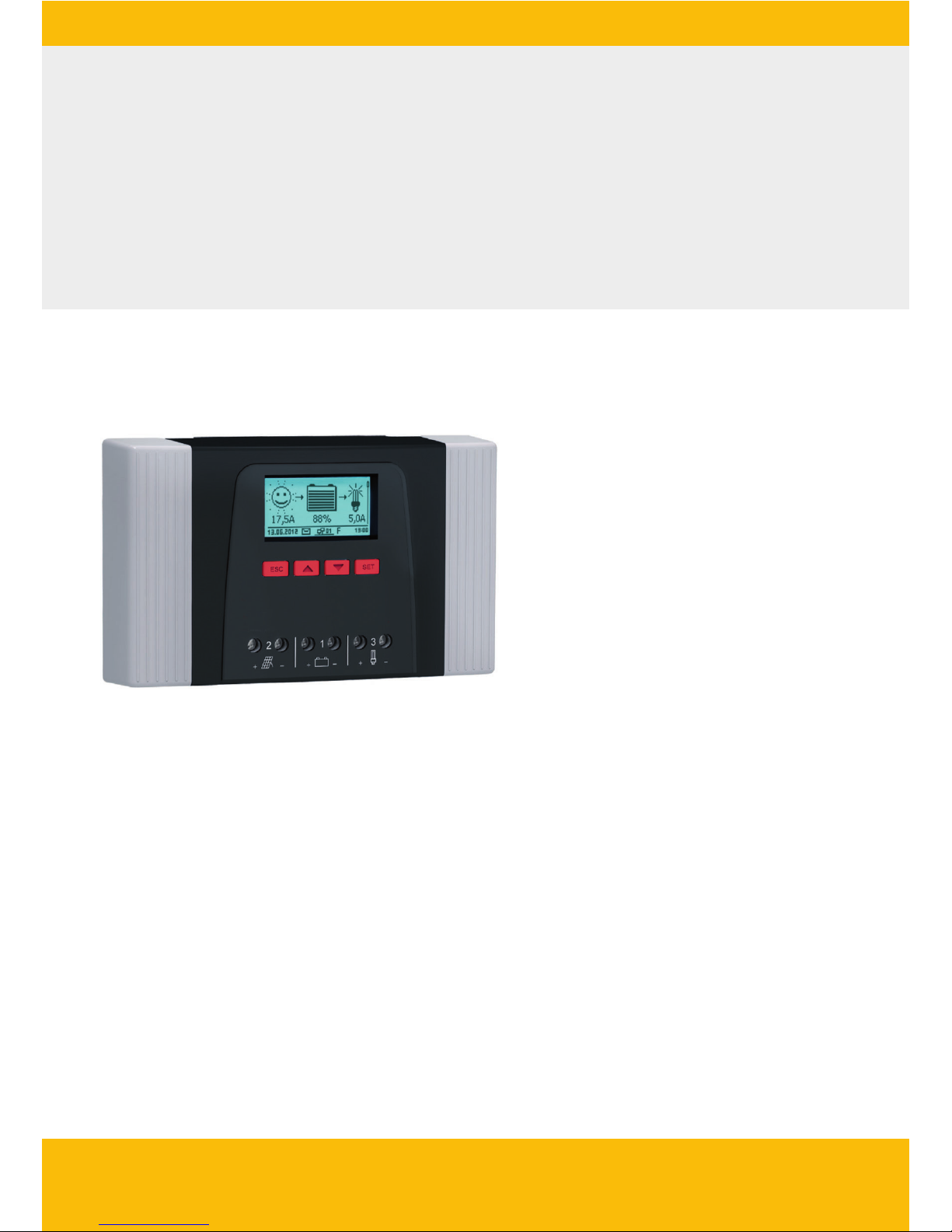
Solar Charge Controller
Adjustable, for hybrid and telecommunication systems
Tarom 4545 (12 V/24 V accumulator)
Tarom 4545-48 (12 V/24 V/48 V accumulator)
Installation and operating instructions
GB
Z03 | 17.05
Page 2

2
DE
1 General safety instructions ................................................................................................. 5
2 Identification ...................................................................................................................... 6
3 Scope of delivery ................................................................................................................ 7
4 Proper usage....................................................................................................................... 8
5 Markings ............................................................................................................................ 9
5.1 Symbols for warnings and notices ........................................................................... 9
5.2 Keywords ................................................................................................................. 9
6 Quick guide ...................................................................................................................... 10
7 Overview of the controller ................................................................................................ 11
8 Menu structure ................................................................................................................. 12
9 Installation ........................................................................................................................ 13
9.1 Safety instructions ................................................................................................. 14
9.2 Connections and operating buttons ...................................................................... 16
9.2.1 StecaLink slave connection ..................................................................... 16
9.2.2 StecaLink master connection .................................................................. 19
9.2.3 Slot for microSD card ( in Fig. 1) .......................................................... 20
9.2.4 Relay outputs AUX 1, AUX 2 (, in Fig. 1) ........................................... 20
9.2.5 Temperature sensor connection TEMP ( in Fig. 1) ................................. 21
9.2.6 Open UART interface, 3.3 V ( in Fig. 1) ................................................. 21
9.2.7 Function ground ( in Fig. 1) ................................................................ 22
9.2.8 Operating buttons .................................................................................. 23
9.3 Removing/installing the cover ................................................................................ 23
9.3.1 Removing the cover ................................................................................ 23
9.3.2 Installing the cover ................................................................................. 24
9.4 Installing the device ............................................................................................... 24
9.5 Establishing the electrical connections .................................................................. 25
9.5.1 Preparing the cables ............................................................................... 26
9.5.2 Connecting the battery ........................................................................... 26
9.5.3 Connecting the solar module .................................................................. 27
9.5.4 Connecting loads .................................................................................... 28
9.5.5 Connecting optional components ........................................................... 29
Table of contents
Page 3

3
DE
10 Performing initial commissioning ..................................................................................... 31
11 Dismounting the controller .............................................................................................. 34
12 System functions .............................................................................................................. 35
12.1 Protection functions .............................................................................................. 35
12.1.1 Controller overload ................................................................................. 35
12.1.2 Overheating of the controller ................................................................. 35
12.1.3 Deep discharging of the battery ............................................................. 35
12.2 Control mode ........................................................................................................ 36
12.3 Battery charging functions .................................................................................... 37
12.3.1 Float charging ......................................................................................... 37
12.3.2 Boost charging ....................................................................................... 37
12.3.3 Equalise charging ................................................................................... 38
12.4 Data logger ........................................................................................................... 38
13 Display (layout, function, operation) ................................................................................ 39
13.1 Overview (menu structure) .................................................................................... 39
13.2 Status display ........................................................................................................ 39
13.3 Display of special states ......................................................................................... 41
13.4 General operation .................................................................................................. 42
13.5 Advanced operation .............................................................................................. 42
14 Control functions .............................................................................................................. 44
14.1 Overview ............................................................................................................... 44
14.2 Operation .............................................................................................................. 45
14.3 Functionality .......................................................................................................... 47
14.3.1 Deep discharge protection ...................................................................... 48
14.3.2 Morning light function ........................................................................... 48
14.3.3 Evening light function ............................................................................ 49
14.3.4 Night light function ................................................................................ 49
14.3.5 Excess energy control ............................................................................. 50
14.3.6 Generator manager ................................................................................ 50
14.3.7 Alarm ...................................................................................................... 51
14.3.8 Timer 1 ... 4 ............................................................................................ 51
Page 4

4
DE
14.3.9 StecaLink bus .......................................................................................... 52
14.3.9.1 StecaLink slave address setting .............................................. 52
14.3.9.2 StecaLink master setting ........................................................ 53
14.3.9.3 Changing the slave settings .................................................. 54
14.3.10 SD card ................................................................................................... 56
15 Troubleshooting................................................................................................................ 58
15.1 Event messages ..................................................................................................... 58
15.2 Errors without event messages .............................................................................. 64
15.3 Self test ................................................................................................................. 65
16 Maintenance ..................................................................................................................... 66
16.1 Controller .............................................................................................................. 66
16.1.1 Removing dust ........................................................................................ 66
16.1.2 Removing heavy soiling .......................................................................... 66
16.1.3 Checking the charging functionality ....................................................... 67
16.1.4 System .................................................................................................... 67
17 Disposal ............................................................................................................................ 68
18 Technical data ................................................................................................................... 69
18.1 Controller .............................................................................................................. 69
18.2 Connection cables ................................................................................................. 71
18.3 Protocol of the open UART interface ..................................................................... 72
18.3.1 Settings .................................................................................................. 72
18.3.2 UART Data .............................................................................................. 73
18.4 Recording data on an SD card ............................................................................... 75
18.4.1 Master data file ...................................................................................... 76
18.4.2 TIMECHG data file ................................................................................... 77
18.4.3 PA HS400 data file .................................................................................. 78
19 Guarantee conditions ....................................................................................................... 79
19.1 Exclusion of liability ............................................................................................... 79
20 Contact ............................................................................................................................. 80
21 Notes ................................................................................................................................ 81
Page 5

5
DE
1 General safety instructions
Q This document is part of the product.
Q Only technical professionals may perform the work described in this manual.
Q Install and use the device only after reading and understanding this document.
Q Always perform the measures described in this document in the sequence specified.
Q Keep this document in a safe place for the entire service life of the device. Pass the document
on to subsequent owners and operators of the device.
Q Incorrect operation can reduce solar system yields or damage system components.
Q The device must not be connected to the DC cables if it has a damaged casing.
Q If one of the following components is damaged immediately take the device out of operation
and disconnect it from the battery and modules
– Device (not functioning, visible damage, smoke, penetration of liquid etc.),
– Connected cables,
– Solar module.
Do not switch the system on again before
– the device has been repaired by a dealer or the manufacturer,
– damaged cables or solar modules have been repaired by a technical specialist.
Q Battery acid splashes on skin or clothing should be immediately treated with soap suds and
rinsed with plenty of water. Immediately seek medical advice in the case of injuries.
Q If battery acid splashes into the eyes, immediately rinse with plenty of water and seek medical
advice.
Q Never cover the device.
Q Do not open the casing: Risk of death. Invalidation of the guarantee.
Q Factory labels and markings must never be altered, removed or rendered unreadable.
Q Observe the manufacturer's manual when connecting an external device that is not described in
this document. Incorrectly connected devices can damage the controller.
Q This device is not intended for
– children,
– persons with physical, sensory or mental impairment,
– persons without sufficient experience or knowledge unless they are instructed in the use of
the device, and initially supervised, by a person responsible for their safety.
Page 6

6
DE
2 Identification
General information
Feature Description
Type Tarom 4545, Tarom 4545–48
Issue version of the manual Z03
Manufacturer's address See nameplate on the charge controller
Optional accessories Q External temperature sensor Steca PA TS-S
Q Current sensor PA HS400
Q StecaLink termination plug
Display
The controller indicates the version of the manual matching the software under ‘Main menu’
‘Information’ ‘System info’
Page 7

7
DE
3 Scope of delivery
Q Tarom 4545 or Tarom 4545–48
Q Operating instructions
Page 8

8
DE
4 Proper usage
The solar charge controller, hereinafter named as the controller or device, may only be used in standalone photovoltaic systems for charging and controlling a lead-acid battery containing liquid or gel
electrolyte. The following applies in addition:
Q The controller must not be connected to the public power grid.
Q Only solar modules may be connected to the solar module connection.
Q Depending on the battery used, the connected loads must be suitable for use with one of the
following voltages:
Tarom 4545: 12 VDC, 24 VDC
Tarom 4545–48: 12 VDC, 24 VDC, 48 VDC
Q The controller performs the following tasks:
– Monitoring of the battery charging process
– Controlling of the charging process, protection of the battery from overcharging
– Switching loads on and off, protection of the battery from deep discharge
Page 9
9
DE
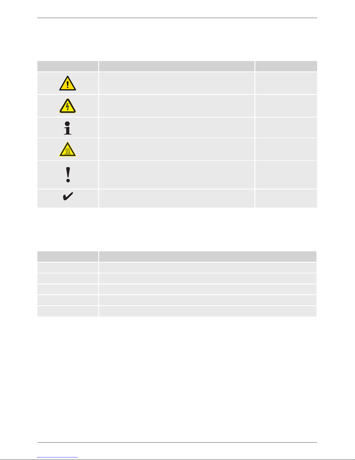
5 Markings
5.1
Symbols for warnings and notices
Symbol Description Location
General danger warning Manual
Danger from electricity Manual
Read the manual before using the product. Device
Danger from hot surfaces Manual, Device
General information. Manual
The following information describes prerequisites for
further operation
Manual
5.2 Keywords
The following symbols are used in conjunction with the symbols from chapter 5.1.
Keyword Description
Danger immediate danger of death or serious bodily injury
Warning possible danger of death or serious bodily injury
Caution possible danger of light or medium bodily injury
Notice possible damage to property
Note note on operation of the device or use of the manual
Page 10
10
DE
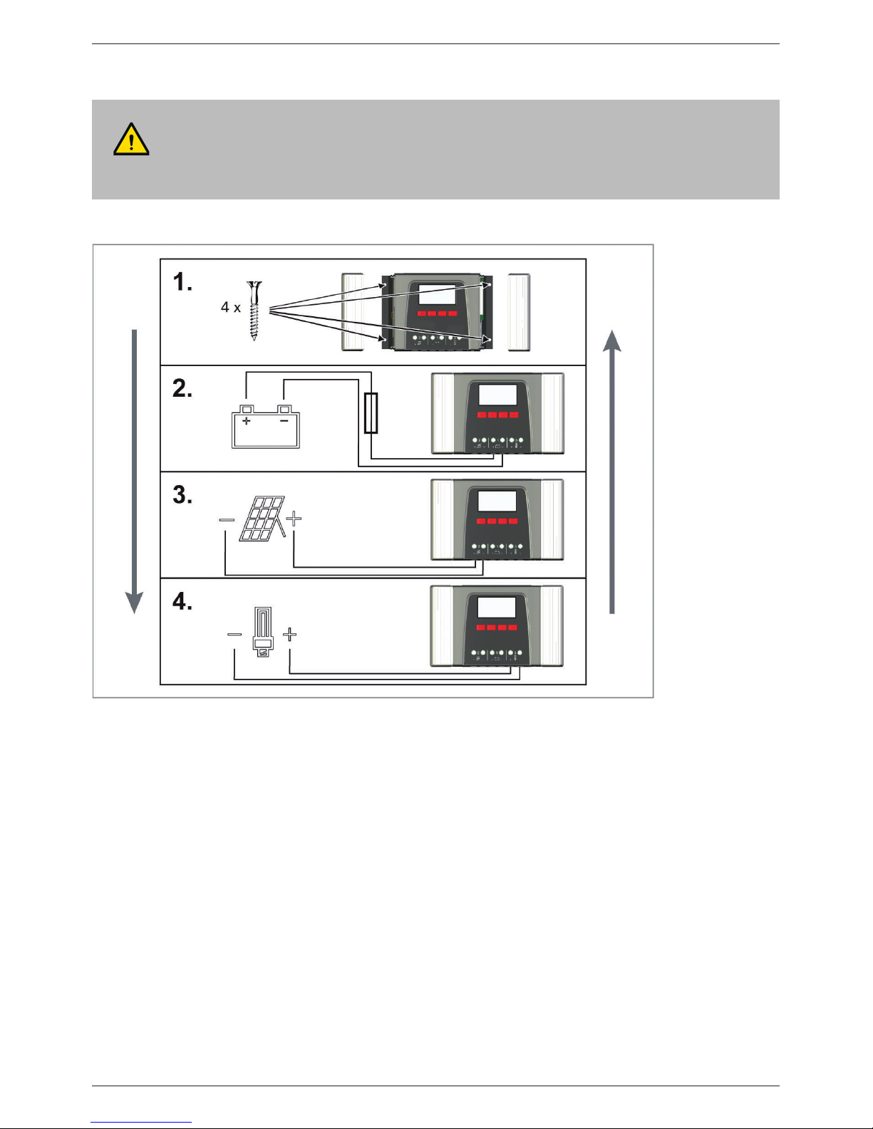
6 Quick guide
DANGER!
Risk of death by electrocution. Observe the safety instructions in chapter 9.1.
Installation
Uninstallation
Page 11

11
DE
7 Overview of the controller
Fig. 1 Overview of casing and connections
1)
Technical data at section 18.1.
2)
Optional
3)
Not included in scope of delivery
Connections
Batteryconnection:terminals1+and1−
Solar module connection: terminals 2+ and
2−
Load output for connecting the loads:
terminals3+and3−
Micro SD slot for microSD card
SLAVE IN and SLAVE OUT RJ45 sockets
for StecaLink Bus
MASTER RJ45 socket for StecaLink Bus
Open UART interface, 3.3 V
Temperature sensor connection TEMP for
Steca PA TS-S
AUX 2 relay output
AUX 1 relay output
Other components
External battery fuse (safety fuse or DC line
circuit breaker
1) 3)
DC load circuit breake
1) 2) 3)
Left cover
Display
Right cover
ESC,
r, s, SET operating buttons
Type plate
Positive ground, optional
Page 12
12
DE
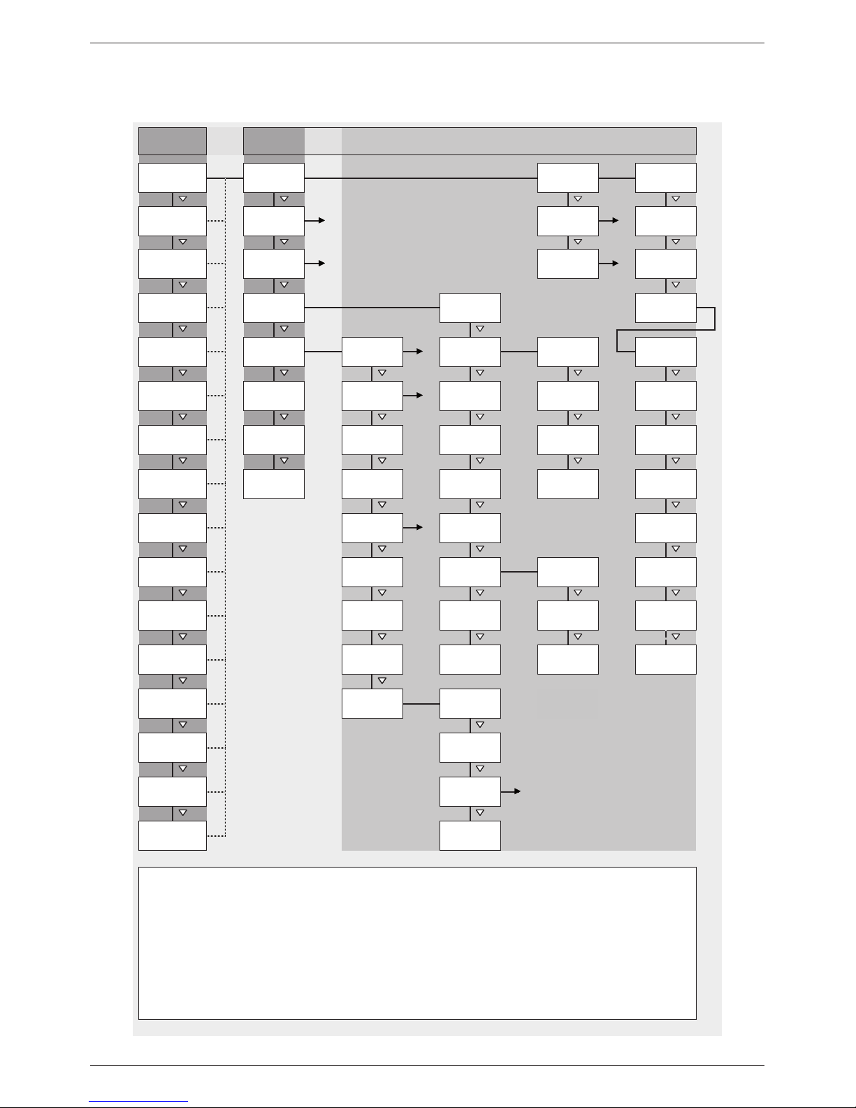
8 Menu structure
For the sake of clarity, only the s and ‘SET’ operating buttons are illustrated.
SET SET SET
SET SET SET
SET SET SET
SET SET SET
SET SET SET SET
SET SET
SET
SET
SET SET
Daily input
Daily load
Information
Load current Clear event log
Event log
Battery type
5)
Time format
Date format
Status display Main menu
Basic setting
Battery voltage
Output settings
Internal data
logger
Charge /
discharge
current
Battery
settings
Battery
capacity
Charge voltage 6)
Contrast
2)
SD card
Date
Time / date
Clear log data
4)
Battery control
mode
Equalisation
cycle
Time
Language
Self test
3)SOC
Input current
System
settings
PV current
Operation
mode
Load
AUX 1
AUX 2
Deep discharge
protection
Select function
Function
settings
8)
8)
Evening light
Night light
Morning light
Submenus
Generator
control
Excess energy
control
StecaLink slave
address
SET
SET
SET
SET SET
SET
SET SET
SET
1)
2)
3)
4)
5)
6)
7)
8)
System voltage
Open UART
Temperature
sensor
Device
temperature
Cable
compensation
Available if battery type = lead acid battery. Submenus: On/Off, cycle
Equalisation
charge
duration
Boost charge
duration
Expert menu
Start boost
charge
Battery
temperature
Remaining
capacity
Operating hours
StecaLink
master menu
Add slave
device
Submenus: SOC control mode, sensor member list
7)
Temperature
compensation
Total charge /
discharge current
of battery
Total discharge
current of battery
Total charge
current of battery
Factory reset
Change slave
Delete slave
Timer 1
Timer 4
Submenus for displaying the stored energy, current and voltage, configuration of sensors
Submenus: Datalogger On/Off, load parameter, store parameter
1)
Measurements of registered StecaLink slaves (if available)
Submenus: Float charging, boost charging, equalisation charging (available if battery type = Lead acid battery)
Submenus: On/Off, temperature coefficient
Same menus as Load, additionally with Alarm
Alarm 9)
)
9)
Only for AUX 1 and AUX 2
Page 13

13
DE
9 Installation
The following section describes only the installation of the controller. Observe the respective
manufacturer's manual when connecting external components (solar module, battery, load,
sensors).
Page 14

14
DE
9.1 Safety instructions
DANGER!
Risk of death by electrocution! Observe the following safety instructions when performing the
measures described in the installation section.
General information
– Only technical professionals may perform the work described in the 'installation' section.
– Do not open the controller case.
– All covers must be installed during operation.
– Always take the following measures before working on the controller:
1. Switch off all loads.
2. If present, switch off the DC load circuit breaker (solar module) and secure it against
being switched on again or safely cover the solar module (wind).
3. Switch off the external battery fuse: Remove the fuse insert from the fuse holder (safety
fuse) or switch off the DC line circuit breaker and secure it against being switched on
again.
4. Disconnect the battery cable from both battery terminals.
Cable connections
– The module cables carry voltage when the solar module is illuminated.
– Insulate exposed cable ends with insulation tape or wire connector blocks.
– Connect the cables for the battery, solar module and loads to the controller in the
described sequence.
– Secure the connected cables with a strain relief clamp, see Quick Guide section 6. Clearance
of strain-relief to controller: 200 mm.
– Connect only 1 cable to each connection terminal.
– Cables used: Observe the specifications in the Technical data section.
– Lay the cables so that
– connections cannot accidentally come loose,
– persons cannot tread on or trip over these,
– fire protection devices must not be impaired.
– The entire installation must be designed with Protection Class II if the open-circuit module
voltage exceeds 60 V DC at least once anywhere over the entire temperature range.
– Observe all applicable installation regulations and standards, national laws and connection
values specified by the regional power supply company.
Fuses and switching devices
Installation of an external battery fuse (line fuse or DC line circuit breaker) is mandatory.
Observe the following:
– Mount the external battery fuse directly next to the battery.
– The external battery fuse must conform to the specifications in the technical data section.
– The external battery fuse is not included in the scope of delivery.
Page 15
15
DE
WARNING!
Danger of acid injuries.
– Do not subject the battery to open flames or sparks.
– Provide adequate ventilation in the installation location of the battery. Inflammable gases
can escape from the battery.
– Follow the charging instructions of the battery manufacturer.
ATTENTION!
Danger of destroying the device through overloading.
– Conform to the technical specifications, especially the connection values. See the type plate
and section 18.
– When selecting the solar module, note that the open-circuit module voltage is higher than
the value specified on the type plate at temperatures below 25 °C.
– Connect only 1 controller to each solar module.
– Tighten the connection terminals as shown: Battery, solar module and loads with
2.5 ... 4.5 Nm
Page 16

16
DE
9.2 Connections and operating buttons
The following section describes the connections and operating buttons. For information on the display and operation see section 13.
9.2.1 StecaLink slave connection
1. Set a unique slave address at the device with the StecaLink slave connection; see section
14.3.9.1 ‘StecaLink slave address setting’.
2. Connect the StecaLink slave connection to the ‘StecaLink master’ connection of the superordinate master device.
3. Use a free ‘StecaLink slave’ connection for looping the connection through further slaves.
NOTICE!
– The StecaLink slave connection is an RS-485 communication interface using a proprietary
bus protocol.
– The StecaLink slave connection allows connection of superordinate communication levels
and control devices. The superordinate communication partner functions as the master and
controls the device via the StecaLink slave interface.
– A standard RJ45 network cable (CAT-5 Patch cable, 1:1) is used for connecting StecaLink
communication bus members.
– The last unused StecaLink slave connection of a communication chain must be terminated.
A termination plug can be acquired separately at your Steca dealer.
– A StecaLink slave device may only be connected to one StecaLink master. Multiple Steca-
Link slave devices are connected to form a communication chain. Only one StecaLink slave
device is connected to the StecaLink master device.
– Up to 5 PA HS 400 current sensor units can be connected via the StecaLink master socket
to a Tarom 4545 / Tarom 4545-48.
– The StecaLink slave bus is not galvanically isolated from the power supply unit of the
Tarom 4545 / Tarom 4545-48.
– At the device, at the StecaLink master connection, a supply voltage is available for slave
devices that do not have an own voltage supply. By connecting a slave to the StecaLink
master, the supply voltage is looped through the slave members.
– Each slave must have its own unique address within a range of 1 to 99. No duplicate ad-
dresses may be present. Set the address of the slave according to the slave manual.
– The maximum length of the entire bus cabling should not exceed 25 m.
– The Tarom 4545 / Tarom 4545-48:
– has 2 StecaLink slave bus connections,
– is a slave for Tarom MPPT 6000-M devices at the StecaLink slave connection,
– has a StecaLink master connection,
– is always the master at the StecaLink master connection.
Page 17
17
DE
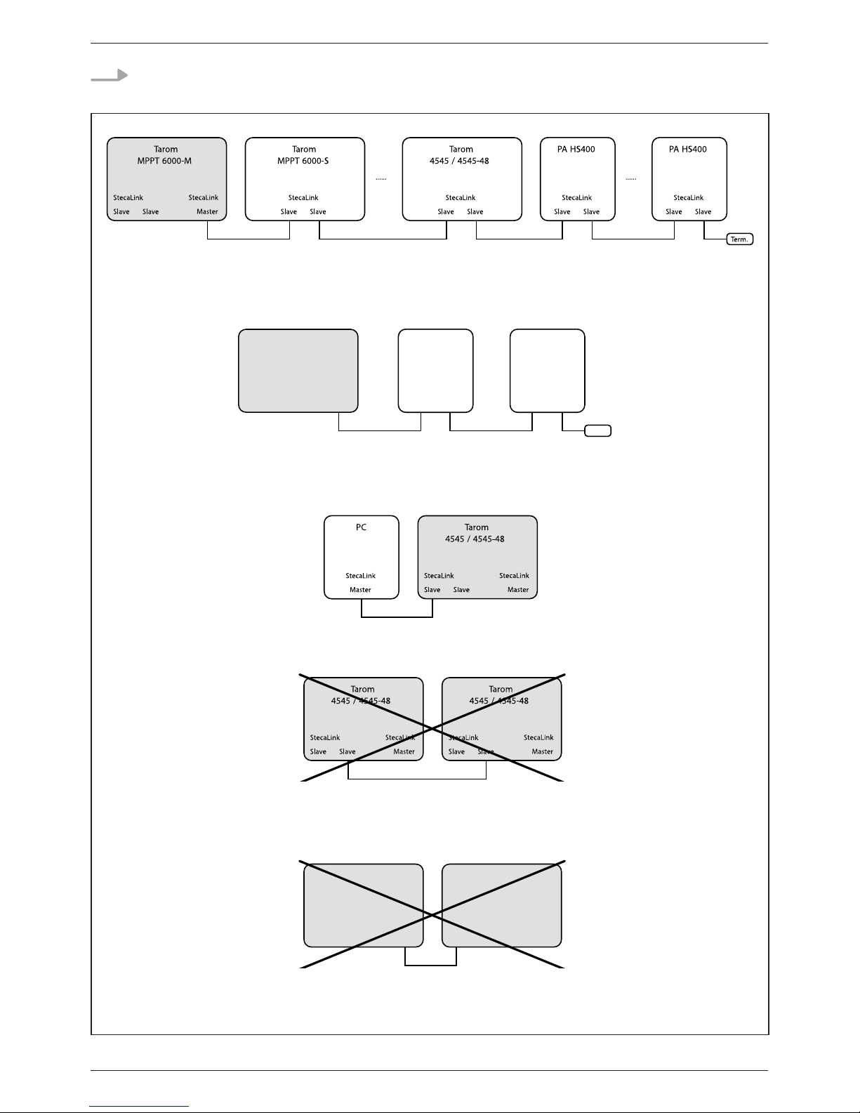
4. Terminate the free ‘StecaLink slave’ connection of the last slave member using the termination plug.
Fig. 2 Bus cabling example using an MPPT 6000-M, MPPT 6000-S, one Tarom 4545/4545-48
and PA HS400 current sensors
Fig. 3 Bus cabling example using one Tarom 4545/4545-48 and one or more PA HS400
current sensors
Fig. 4 Example of connecting a PC to the Tarom 4545/4545-48, e.g. for the update function
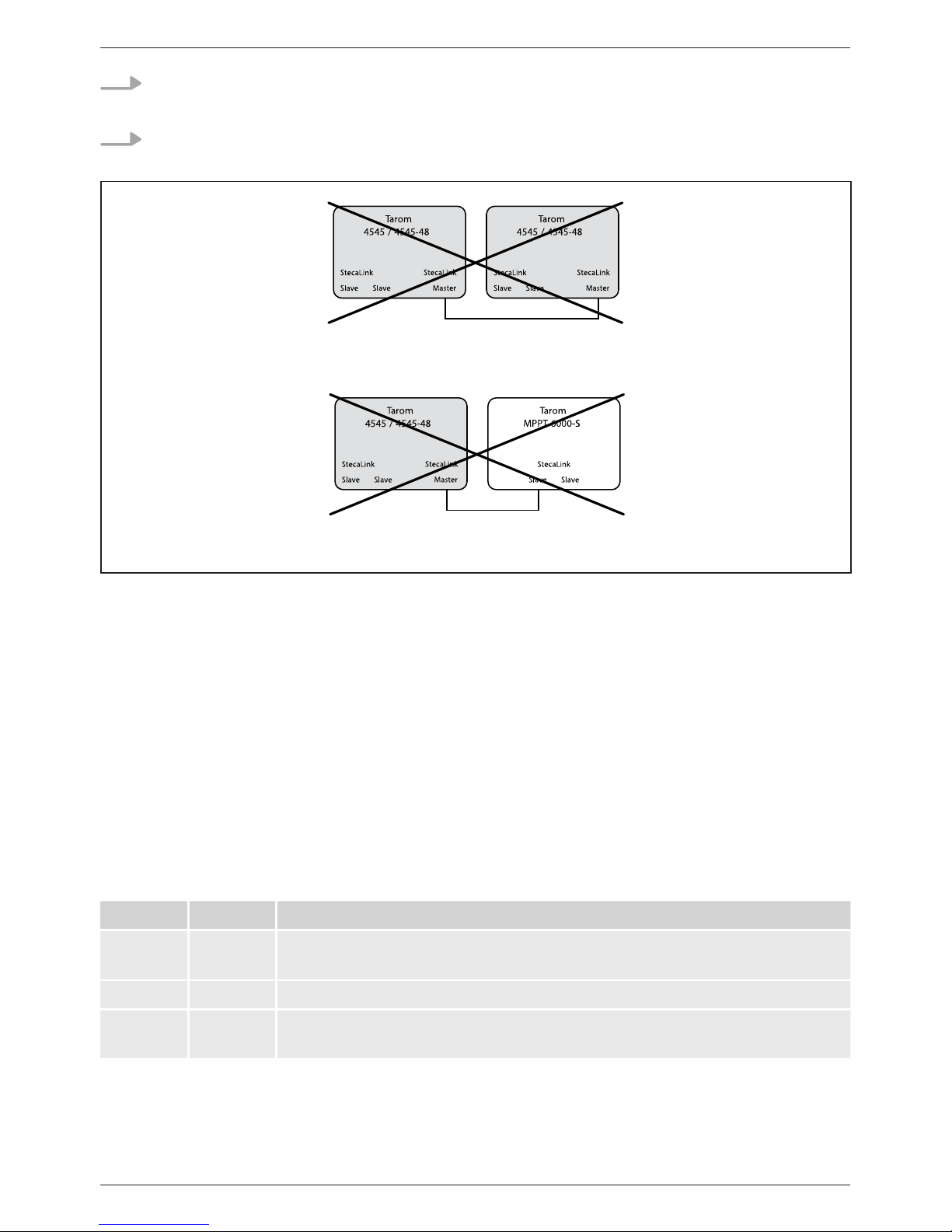
Fig. 5 The connection of Tarom 4545/4545-48 slave connection to other Tarom 4545/4545-48
slave connections, other charge controllers or PA HS400 without master is not permitted
Fig. 6 The connection of Tarom 4545/4545-48 master connection to other Tarom 4545/4545-48
slave connections is not permitted
Tarom
4545 / 4545-48
StecaLink
Slave Slave
StecaLink
Master
PA HS400
StecaLink
Slave Slave
......
PA HS400
StecaLink
Slave Slave
Term.
Tarom
4545 / 4545-48
StecaLink
Slave Slave
StecaLink
Master
Tarom
4545 / 4545-48
StecaLink
Slave Slave
StecaLink
Master
Page 18
18
DE
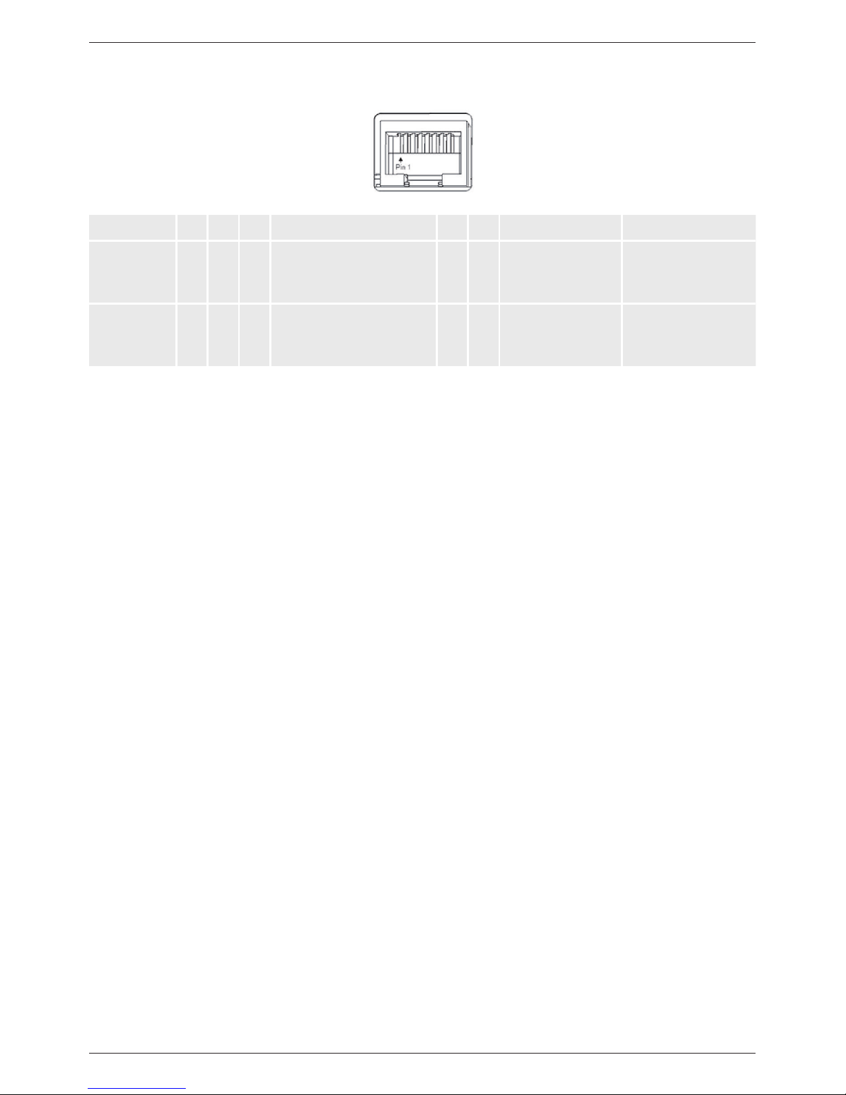
The bus cable pin assignments are specified in the following table.
Pin 1 2 3 4 5 6 7 8
Signal
(master
socket)
A B - + Battery voltage
1)
- - GND
2)
GND
2)
Signal
(slave
socket)
A B - - - - GND
2)
GND
2)
1)
The battery voltage is looped through from the master as supply voltage for slaves.
2)
GND or rather battery minus
Page 19
19
DE
9.2.2 StecaLink master connection
1. Set a unique slave address on the device with the StecaLink slave connection, see section
14.3.9.1 'StecaLink slave address setting'.
2. Plug the slave device into the StecaLink master connection. Connect the 'MASTER for Steca-
Link Bus' connection to the 'SLAVE IN for StecaLink Bus' connection.
3. If further slaves shall be connected, connect them via the slave device, at its free 'SLAVE OUT
für StecaLink Bus' connection.
NOTICE!
– The StecaLink master connection is an RS-485 communication interface using a proprietary
bus protocol.
– The StecaLink master connection allows the connection of subordinate communication
partners.
– The StecaLink slave devices connected to the StecaLink master connection are controlled by
the Tarom 4545 / Tarom 4545-48 as communication master.
– E.g. external current sensors PA HS400 can be connected to the StecaLink master connecti-
on.
– A standard RJ45 network cable (CAT-5 Patch cable, 1:1) is used for connecting StecaLink
communication bus members.
– Termination plugs for the StecaLink communication bus are available as accessories.
The communication network connected to the StecaLink master must be terminated at the
last free StecaLink slave connection.
– No further StecaLink master may be used in the communication network that is connected
to the StecaLink master connection.
– The Tarom 4545 / Tarom 4545-48 can manage a maximum of 5 PA HS400 units.
– Each slave must have its own unique address within a range of 1 to 99. No duplicate ad-
dresses may be present. Set the address of the slave according to the slave manual.
– The maximum length of the entire bus cabling should not exceed 25 m.
– The controller:
– has 1 StecaLink master connection,
– has 2 StecaLink slave bus connections,
– is always the master at the StecaLink master connection.
ATTENTION!
Tarom 4545 / Tarom 4545-48 devices can only communicate via the StecaLink bus if they have
a serial number from 757324 / 757325 or higher, as well as a APP software version 1.7.0 or
higher.
It is never permitted to integrate more than one Tarom 4545 / Tarom 4545-48 in a StecaLink bus
because otherwise dangerous compensation currents may occur!
Page 20
20
DE
4. On the last slave member, terminate the free 'StecaLink Slave' connection with the termination plug.
5. Register and configure the added StecaLink slave devices on the master device, see section
14.3.9.2 ' StecaLink master setting'.
Fig. 7 Master/slave connection of two Tarom 4545/4545-48 via the master connection
is not possible
Fig. 8 Tarom 4545/4545-48 / Tarom MPPT 6000-S connection is not possible without Tarom
MPPT 6000-M
StecaLink bus cable pin assignment: see page 23.
9.2.3 Slot for microSD card ( in Fig. 1)
Data can be logged and parameters can be saved on an inserted microSD card (not included in
scope of delivery). See 'Commissioning of the microSD card' in section 9.5.5.
9.2.4 Relay outputs AUX 1, AUX 2 (, in Fig. 1)
The relay outputs can be used for switching devices or loads (loads via an external power relay).
Devices connected to the relay outputs are controlled via the control functions provided by the controller. Relay output pin assignments:
AUX 1 AUX 2 Description
1 (NC) 4 (NC) Normally closed relay contact; the contact is closed when the relay is
switched off.
2 (COM) 5 (COM) Common relay contact
3 (NO) 6 (NO) Normally open relay contact; the contact is open when the relay is
switched off.
Page 21

21
DE
9.2.5 Temperature sensor connection TEMP ( in Fig. 1)
If the controller and battery are not located in the same room then an external temperature sensor
for measuring the battery temperature must be installed. We recommend using the optionally available Steca PA TS-S. Pin assignments:
Pin 7 (EXT.) 8 (GND)
Signal Sensor connection
1)
Sensor connection
1)
1)
Any polarity can be used.
9.2.6 Open UART interface, 3.3 V ( in Fig. 1)
The open UART interface outputs the values measured by the controller.
The interface can be switched on and off.
Interface protocol: see section 18.3.
Pin assignments:
Pin 9 (GND) 10 (TX) 11 (RX)
Signal Battery minus TX RX
Heavy loads directly connected to the battery can be switched using an additional power relay
connected to the AUX 1 or AUX 2 outputs, e.g. via the Steca PA EV 200.
Page 22
22
DE
9.2.7 Function ground ( in Fig. 1)
DANGER!
Risk of death by electrocution. Grounding causes the system to leave the safety extra-low
voltage range. Protection against directly touching live components must be restored via appropriate isolation measures.
The controller does not need to be grounded in stand-alone systems. We recommend not
grounding the controller. Also observe the local regulations.
If required, the controller can be grounded via the positive battery terminal '1+' Bat+ Fig. 1 of the
controller.
Observe the following:
Q The connection point must lie between the external battery fuse and the controller.
Q The connection point can be used as a common ground for all system components.
Q Take the grounding of the entire system into account.
ATTENTION!
– The system voltage of thin-film modules must be positive to avoid corrosion. This require-
ment is satisfied in stand-alone systems that are not grounded.
– Danger of damaging the devices (e.g. computer) connected to the Master/Slave bus or the
UART interface. All bus connections must be galvanically isolated when the system is
grounded.
Page 23
23
DE
9.2.8 Operating buttons
The operating buttons have the following functions:
Button Function
SET Q jumps down by one menu level
Q changes the state of a control element (check box/radio button)
Q causes the selected numeral to blink so that it can be modified
Q answers a query dialog with Yes
Q adopts a change
ESC Q jumps up by one menu level
Q jumps to the status display (press for 1 s)
Q answers a query dialog with No
Q discards any changes
r/s Q moves the selection bar or the display content upwards/downwards
Q moves the selection 1 position to the left/right on a settings page
Q increases/reduces the setting value by 1 step
Q repeated button presses: press button for a longer time
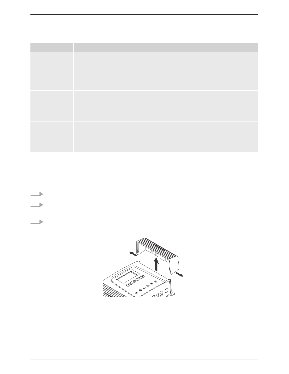
9.3 Removing/installing the cover
9.3.1 Removing the cover
1. Grip the cover with both hands as shown in Fig. 9.
2. Use your index fingers to pull the edges slightly outwards and then pull upwards so that the
cover is released from the end position.
3. Pull off the cover entirely by lifting it upwards.
Fig. 9 Release the cover from the end position (here the right cover)
1.
2.
1.
Page 24
24
DE
9.3.2 Installing the cover
1. Position the cover on the casing so that the two guide lugs on the cover fit into the guide
slots in the casing.
2. Slide the cover onto the casing until it audibly latches into place.
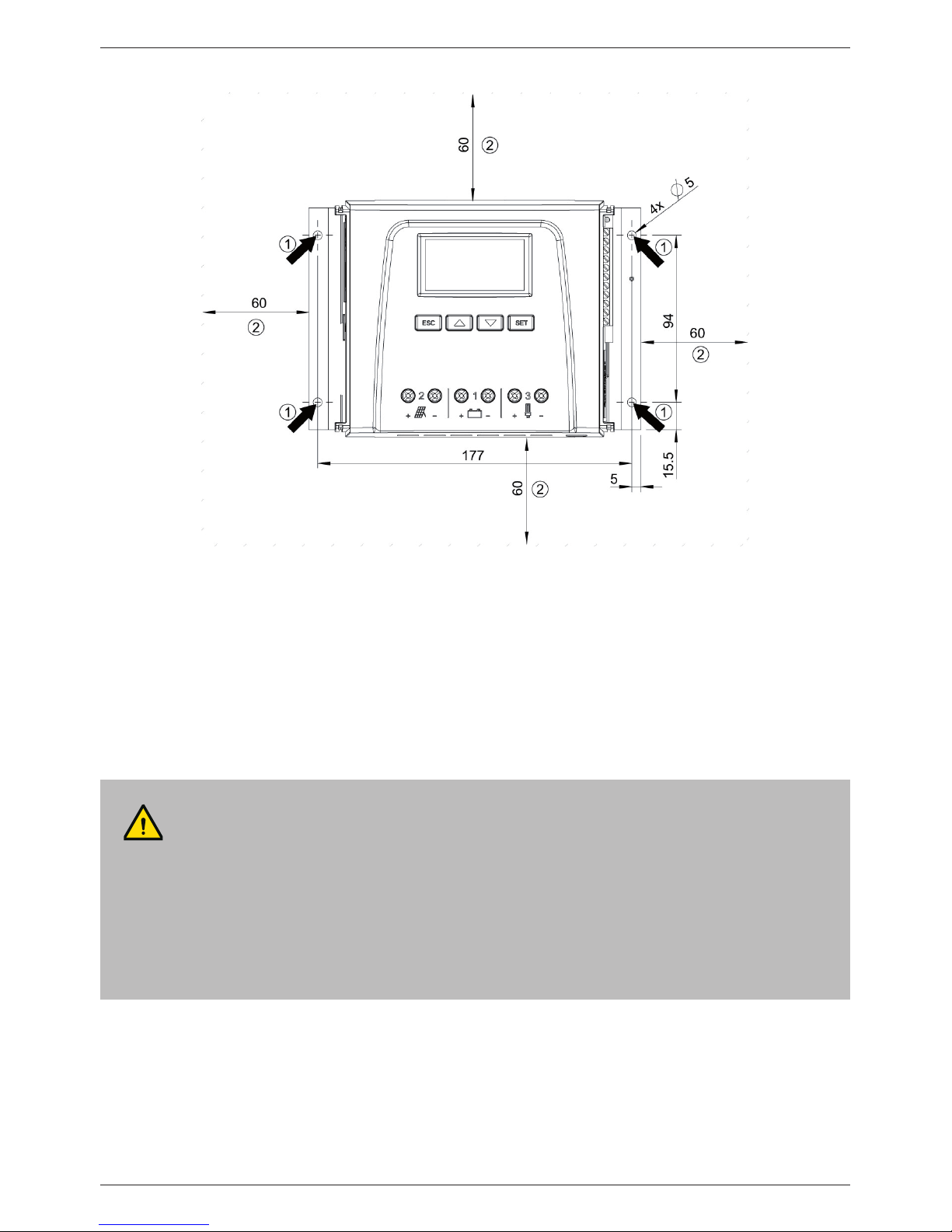
9.4 Installing the device
1. Select the mounting location under consideration of the previously mentioned safety requirements.
2. Remove both controller covers.
3. Position the controller level on the mounting surface and mark the mounting holes through
the fastening openings .
4. Remove the controller and drill the mounting holes.
5. Use 4 suitable screws (max. M5) to fasten the controller to the mounting surface.
6. Install the covers.
ATTENTION!
Danger of damage to the controller and reduction of power. Observe the following safety
requirements during installation:
– The mounting location and immediate environment are permanently fixed, vertical, flat,
non-inflammable and not subject to constant vibration.
– A free space of at least 60 mm must be present on all sides of the controller. The required
free space relates to the controller without covers; see in Fig. 10.
– The controller must be easily accessible and the display easily readable.
– The controller is mounted as close as possible to the battery; the prescribed minimum
safety clearance of 0.5 m between the controller and battery is adhered to.
– The controller must not be located
– outdoors or in a location subject to rain or splashing water,
– in dusty environments,
– in areas with active animal husbandry,
– in direct sunlight.
– The battery cable is no longer than 2 m (recommended), to keep cable losses and compen-
sating voltage as low as possible.
– Do not drill through the fastening openings (Fig. 10).
Page 25
25
DE
Fig. 10 Fastening openings and free space
9.5 Establishing the electrical connections
Always make connections in the following sequence:
CAUTION!
Always make connections in the following sequence:
1. First connect the load and then the source.
Example: First connect the cable to the controller and then to the battery.
2. Connect the positive pole first then the negative pole.
Example: First connect B+ then B–.
Page 26

26
DE
9.5.1 Preparing the cables
1. Label the cable ends as per Fig. 1 (M+, M–, B+, ...).
2. Lay the battery, module and load cables directly next to each other. Do not yet connect the
cables!
3. Connect the external battery fuse, close to the battery and easily accessible, to the battery
cable B+ ( in Fig. 1).
4. Switch off the external battery fuse: Remove the fuse insert from the fuse holder (safety fuse)
or switch off the DC line circuit breaker and secure it against being switched on again.
5. Connect the optional DC load circuit breaker, close to the controller and easily accessible, to
the module cable M+ ( in Fig. 1).
6. Switch off the DC load circuit breaker and secure it against being switched on again.
9.5.2 Connecting the battery
No devices are connected to the battery.
1.
Connect the battery cable and external battery fuse to the battery connection of the control-
ler and to the battery.
2. Switch on the external battery fuse: Insert the fuse insert into the fuse holder (safety fuse) or
switch on the DC line circuit breaker . The controller automatically starts operation and, after
a few seconds, displays the detected system voltage (= battery voltage) in an event message
(Fig. 11).
3. Note the system voltage displayed in Fig. 11.
4. Press ‘ESC’ to confirm the event message. The basic setting display appears (Fig. 12).
5. Confirm other event messages with ‘ESC’ , e.g. ‘RTC not set’ .
6. If Fig. 11 and Fig. 12 are not displayed then check the installation and if necessary correct the
error using section 15.
7. Check that the noted system voltage corresponds to the actual battery voltage. If not, set
the system voltage in the expert menu (‘Main menu’
‘Battery settings’ ‘Expert menu’
‘System voltage’; more information on this is provided in section 13.5).
CAUTION!
Danger of damage to the controller. Observe the maximum battery voltage as per
section 18.1.
Page 27

27
DE
Fig. 11 Event message with the detected system voltage (in the example: 12 V)
Fig. 12 Basic setting of the status display
9.5.3 Connecting the solar module
1. Safely cover the module (wind)
2. Connect the module cable and optional DC load circuit breaker to the solar module connection of the controller and to the solar module.
3. Remove covers from the solar module and, if present, switch on the DC load circuit breaker.
The display shows Fig. 13 or Fig. 14.
4. If Fig. 13/Fig. 14 is not displayed, check the installation and if necessary correct the error on
the basis of section 15.
Fig. 13 Display with sunshine after connecting the solar module (possibly delayed)
The battery can be charged from multiple sources. The following applies:
– The battery can be charged by multiple controllers connected to the battery in parallel.
– Apart from the controller, other suitable charging sources can also be connected to the bat-
tery. These charging sources can be switched on and off by the controller via the
‘AUX 1’ and ‘AUX 2’ relay outputs.
Page 28

28
DE
Fig. 14 Display without sunshine after connecting the solar module
9.5.4 Connecting loads
1. Switch off the load output (section 13.5 'Switching loads on/off (load output)').
2. Connect the load cable to the loads and to the load output of the controller.
3. Switch on the load output. The lamp (Fig. 15) appears on the display.
4. Switch on the load. Load currents greater than 0.1 A are shown on the display.
5. If Fig. 15 is not displayed then check the installation and if necessary correct the error using
section 15.
Fig. 15 Display content after connecting the load output
CAUTION!
– Danger of destroying the controller through overloading.
– Loads that consume more current than can be supplied by the controller must be
directly connected to the battery!
– Always directly connect inverters to the battery!
– Danger of battery destruction due to deep discharging. Consumers that are not allowed
to be switched off by the deep discharge protection of the controller (emergency lighting,
radio link) must be directly connected to the battery and must not deeply discharge the
battery.
– Danger of battery and cable destruction due to overloading. Directly connected loads must
be separately fused.
Page 29

29
DE
9.5.5 Connecting optional components
Installing cable strain relief
Secure the cables with a strain relief clamp. Clearance to controller: 200 mm.
Connecting function ground
Connect ground to positive battery terminal '1+' Bat+ Fig. 1 (observe section 9.2.7).
Installing lightning protection
Install suitable lightning protection.
Connecting relay outputs 1 and 2
1. Connect external components to the relay outputs ‘AUX 1‘ und ‘AUX 2‘.
2. Configure the relay outputs as per section 14.
Connecting the external temperature sensor Steca PA TS-S
1. Install the temperature sensor Steca PA TS-S near to the battery.
2. Connect the sensor cable to contacts 7 (‘EXT.’) and 8 (‘GND’) (any polarity).
3. Set the temperature sensor under ‘Main menu’
‘Battery settings’ ‘Temperature sensor’
to ‘external’.
StecaLink bus: connecting master and slave devices
1. Set the addresses of suitable slave devices (observe section 9.2.1).
2. Connect the slave devices to the StecaLink bus.
3. Connect the StecaLink bus to the ‘MASTER’ RJ45 socket.
4. Connect the slave bus to the ‘SLAVE IN’ and ‘SLAVE OUT’ RJ45 sockets.
5. Terminate the last slave device according to the manufacturer's instructions.
Controller: plug optionally available termination plug into the open socket 'SLAVE IN' / 'SLAVE
OUT' on the last controller.
Connecting the open UART interface
Connect external devices to the open UART interface (observe in section 9.2.6).
CAUTION!
Danger of destruction of the relays. Observe the technical data of the relays (section 18)!
Maximum length of the Master bus cable: see section 18.2.
Page 30

30
DE
Commissioning the microSD card
1. Insert a formatted microSD card.
2. Configure the data logging function and save/load the parameters as described in section
14.3.10 'SD card'.
CAUTION!
Never forcibly insert or remove the microSD card. This can damage the card holder and/or the
microSD card.
NOTICE
– A microSD card is not included in the scope of delivery for the device.
– microSD and microSDHC cards with a capacity of up to 8 GB can be used.
– The microSD card must be formatted with a FAT16 or FAT32 file system.
– Using the microSD card, the data of the device as well as of connected StecaLink slave
devices can be recorded.
– Using the microSD card, setting parameters of the device can be saved and read in.
– Take care to observe the correct insertion direction, as shown on the microSD card and the
device.
– Carefully and gently push the microSD card into the opening in the device casing until it
latches into place.
– Remove the microSD card by pushing it towards the device until it unlatches, then let go of
the card and, finally, pull the card out (Push-Pull connector).
– Data recording onto the SD card is deactivated at the factory.
Page 31

31
DE
10 Performing initial commissioning
All the measures described in section 9.4 and section 9.5 have
been completed.
Showing the basic setting of the status display
If necessary, press ‘ESC’ for 1 s to show the basic setting of
the status display.
Setting the language
1. Press ‘SET’. The main menu appears and the ‘Output
settings’ entry is selected (Fig. left).
Note
English is set as the default menu language at the factory
2. Press
s 3 times to select 'System settings'.
3. Press ‘SET’. The ‘System settings’ menu appears and
‘Language’ is selected (Fig. left).
4. Press ‘SET’ . The ‘Language’ menu appears (Fig. left).
5. Press
r s to select a different language.
6. Press ‘SET’.
ATTENTION!
Danger of damage to the device and reduction of power. Only technical professionals may
perform the work described in this section.
Page 32

32
DE
Setting the time
1. Press ‘ESC’. The ‘System settings’ menu appears (Fig. left).
2. Press
s to select ‘Time/date’.
3. Press ‘SET’. The ‘Time/date’ menu appears and ‘Time’ is selected.
4. Press ‘SET’. The ‘Time setting’ dialog appears (Fig. left).
5. Press ‘SET’. The hour flashes.
6. Press
rs to change the hour.
7. Press ‘SET’. The hour stops flashing.
8. Press
s. The minutes are selected.
9. Repeat steps 5 to 7 for setting the minutes.
Setting the date
1. Press ‘ESC’. The ‘Time/date’ menu appears.
2. Press
s to select ‘Date’.
3. Press ‘SET’. The ‘Date setting’ dialog appears (Fig. left).
4. Press ‘SET’. The day flashes.
5. Press
sr to change the day.
6. Press ‘SET’ . The day stops flashing.
7. Press
s to select the month.
8. Repeat steps 4 to 6 for setting the month.
9. Press
s to select the year.
10. Repeat steps 4 to 6 for setting the year.
Setting the battery type
1. Press ‘ESC’ for 1 s. The basic setting display appears
2. Press ‘SET’. The main menu appears.
3. Press
s to select ‘Battery settings’.
4. Press ‘SET’. The ‘Battery settings’ menu appears.
5. Press
s to select ‘Battery type’.
6. Press ‘SET’ . The ‘Battery type’ dialog appears (Fig. left).
7. Press
sr to select a different battery type.
8. Press ‘SET’. The selected battery type is set.
Page 33

33
DE
Setting the battery capacity
1. Press ‘ESC’. The ‘Battery settings’ menu appears.
2. Press
s to select ‘Battery capacity’.
3. Press ‘SET’. The ‘Battery capacity’ dialog appears (Fig. left).
4. Press ‘SET’.
5. Press
sr to change the value.
6. Press ‘SET’. The value stops flashing.
Setting the control mode
Note
The control mode ‘State of charge (SOC)’ is preset at the factory
and only needs to be changed if required. More information on
this is provided in section 12.2.
1. Press ‘ESC’. The ‘Battery settings’ menu appears.
2. Press
s to select ‘Battery control mode‘.
3. Press ‘SET‘, the ‘SOC Control mode‘ dialogue appears.
4. Press
sr to select ‘Voltage control’.
5. Press ‘SET’. The voltage control is set.
Switching off cable compensation
Note
Cable compensation is switched on at the factory and only needs
to be switched off if required. More information on this is provided
in section 12.2.
1. Press ‘ESC’. The ‘Battery settings’ menu appears.
2. Press
sr to select ‘Cable compensation‘’
3. Press SET. The ‘Cable compensation’ dialog appears.
4. Press
sr to select ‘Off’.
5. Press ‘SET’. Cable compensation is switched off (Fig. left).
Finishing initial commissioning
Press ‘ESC’ for 1 s. The basic setting of the status display
appears and initial commissioning is finished.
Note
You can usually now use the controller without making any further
settings. For information on important additional functions see
section 14.
Page 34

34
DE
11 Dismounting the controller
Disconnecting the loads from the controller
1. Switch off all loads.
2. Disconnect the load cables L− and L+ from the controller.
Disconnecting the solar module from the controller
3. If present, Switch off the DC load circuit breaker (solar module) and secure it against being
switched on again or Safely cover the module (wind).
4. Disconnect the module cables M− and M+ from the controller and insulate the cable ends
Disconnecting the battery from the controller
5. Switch off the external battery fuse: Remove the fuse insert from the fuse holder (safety fuse)
or switch off the DC line circuit breaker and secure it against being switched on again.
6. Disconnect the battery cables B− and B+ from the controller and insulate the cable ends.
Finishing dismounting
7. If present, disconnect any remaining components from the controller (buses, sensors etc.).
8. Remove the controller from the mounting surface.
DANGER!
Risk of death by electrocution. Only technical professionals may perform the work described in
this section. Observe the warning notes in section 9.1.
WARNING!
Danger from hot surfaces. Allow the heatsink on the rear of the device to cool down before
touching.
Page 35

35
DE
12 System functions
12.1
Protection functions
12.1.1 Controller overload
The controller is protected from the following faults and is not damaged when these faults occur
individually.
Q Solar module or battery or load connected with the wrong polarity
Q Solar module or battery or load incorrectly connected
Q Solar module or load short-circuited
Q Battery not connected
Once the individual fault has been corrected the controller will operate correctly without taking any
further measures.
If the battery voltage drops below 9.5 VDC, safe operation of the controller can no longer be
guaranteed. The controller stops all functions, especially charging of the battery.
12.1.2 Overheating of the controller
The cooling fins on the rear side and the internal temperature controller prevent the controller from
overheating. If the controller becomes too hot then the battery is no longer charged and the load
output is also switched off if necessary.
12.1.3 Deep discharging of the battery
To protect the battery from deep discharge the controller switches off the load output and the
‘AUX 1’ and ‘AUX 2’ relay outputs if necessary. More information on this is provided in section 14.
ATTENTION!
The following faults damage the controller:
– At least 2 of the above mentioned faults occur simultaneously.
– The load outputs of multiple controllers are connected in parallel.
– A solar module is connected to multiple controllers in parallel.
Page 36

36
DE
12.2 Control mode
The controller has 2 control modes:
Q Based on the actual state of charge of the battery (SOC control)
Q Based on the battery voltage (voltage control)
The use of the SOC control is strongly recommended because a longer battery life can be
expected by using it.
When SOC control is switched on the charge state of the battery is displayed in percent, with
Voltage control the charge state is displayed in volts. The following applies in addition:
Q If components are connected directly to the battery, the controller can only determine the SOC
correctly if it measures the battery currents with device-specific Steca current sensor PA HS400.
If it is not possible to measure the battery currents, the controller must be changed to Voltage
control.
Q The controller takes the battery temperature into account for accurate determination of the
charge completion voltage. To do this, the controller measures the room temperature using its
own internal temperature sensor and assumes that the battery is also at room temperature. If
the battery is located in a different room then the external temperature sensor Steca PA TS-S
(optional) should be used.
Q The voltage drop in the battery cables distorts the battery voltage measurement of the battery
and, thus, the actual charging voltage present at the battery. The cable compensation of the
controller compensates for this voltage drop. Additional sensors are not required. Cable compensation is switched on in the factory settings.
Operation
Q Control mode: ‘Main menu’
‘Battery settings’ ‘Battery control mode’
Q Temperature sensor: ‘Main menu’
‘Battery settings’ ‘Temperature sensor Bat.’
Q Cable compensation: ‘Main menu’
‘Battery settings’ ‘Cable compensation’
Page 37

37
DE
12.3 Battery charging functions
12.3.1 Float charging
When the battery is fully charged, the controller automatically switches to float charging (charging
with the float charge voltage). This prevents the battery from being discharged.
ATTENTION!
The float charging voltage must be set according to the specifications of the battery manufacturer to ensure optimum charging of the battery.
Operation
Float charging voltage: ‘Main menu’
‘Battery settings’ ‘Charge voltages’ ‘Float charging’
12.3.2 Boost charging
Boost charging provides more intensive care of the battery than float charging. The following
applies in addition:
Q Boost charging starts when the switch-on threshold1) is reached. Boost charging can also be
started manually.
Q Boost charging stops after the charge duration has expired.
Q With boost charging the charging voltage is higher than with float charging.
Q After boost charging the controller automatically switches to float charging.
Observe the manufacturer's specifications when setting the charge duration and charge completion voltage.
Operation
Q Switch-on threshold: ‘Main menu’
‘Battery settings’ ‘Charge voltages’ ‘Boost
charging’ ‘Starting threshold’
Q Charge duration: ‘Main menu’
‘Battery settings’ ‘Expert menu’
2)
‘Boost charge dur.’
Q Charge completion voltage: ‘Main menu'
‘Battery settings’ ‘Charge voltages’
‘Boost charging’ ‘Boost charge voltage’
Q Starting boost charging manually: ‘Main menu’
‘Battery settings’ ‘Start boost charge’
1)
Value in percent with SOC control, in volts with voltage control
2)
More information on this is provided in section 13.5 'Calling up the expert menu for battery set-
tings'.
Page 38

38
DE
12.3.3 Equalise charging
Equalise charging prevents acid layering via controlled gassing and thus extends the service life of
the battery. The following applies in addition:
Q Equalise charging starts when the cycle has expired or the switch-on threshold
1)
is crossed.
Q Equalise charging stops after the charge duration has expired.
Q Equalise charging is switched on in the factory settings. Prerequisite: battery type = ’Lead acid
battery’.
Q After equalise charging, the controller automatically changes to float charging.
Operation
Q Generally switching equalise charging on/off: ’Main menu’
’Battery settings’ ’Equal.
charging cycle’ ’On/off'’
Q Cycle: ’Main menu’
’Battery settings’ ’Equal. charging cycle’ ’Cycle duration’
Q Switch-on threshold: ‘Main menu’
‘Battery settings’ ‘Charge voltages’ ‘Equal.
charging’ ‘Starting threshold’
Q Charge completion voltage: ’Main menu’
’Battery settings’ ’Charge voltages’ ’Equal.
charging’ ’Equal. charging voltage’
Q Battery type: ‘Main menu’
‘Battery settings’ ‘Battery type’
Q Charge duration: ‘Main menu’
‘Battery settings’ ‘Expert menu’
2)
‘Equal. charge dur.’
1)
Value in percent with SOC control, in volts with voltage control
2)
More information on this is provided in section 13.5 'Calling up the expert menu for battery set-
tings'.
12.4 Data logger
The data logger stores the following data in internal memory:
Q Energy input
Q Energy output
Q Min. battery voltage
Q Max. battery voltage
Q Max. input current
Q Max. load current
Internally stored data is shown on the display and can be deleted.
– Observe the manufacturer's specifications when setting the cycle and charge duration.
– Equalise charging is only possible if the battery type 'Lead acid battery' is set.
Page 39

39
DE
13 Display (layout, function, operation)
13.1
Overview (menu structure)
An overview of the operating structure of the display is provided on section 8.
13.2 Status display
The status display consists of the Basic setting, the pages with the Measurements and the Information bar.
Basic setting
The Solar module/system symbol shows the status of the
solar module and the system as follows:
The solar module is illuminated and the controller has
detected the Day condition. No event message or a
message of type Information1) is present.
The solar module is illuminated and the controller has
detected the Day condition. An event message of
type Warning
1)
or Error1) is present.
The solar module is not illuminated and the controller
has detected the Night condition. No event message
or a message of type Information
1)
is present
The solar module is not illuminated and the controller
has detected the Night condition. An event message
of type Warning
1)
or Error1) is present.
Input current in amperes
The Battery symbol indicates charging of the battery as
follows:
Battery almost full
Battery almost empty
Charge state of the battery in % or volts.
With SOC control: Charge state in %
With voltage control: Battery voltage in volts
The Load symbol is shown when the load output is
switched on.
Load current in amperes
1)
More information on this is provided in section 15.1.
Page 40

40
DE
Measured values
Name of the measured value
Measurement with units
The following measurements are displayed:
Q Battery voltage
Q SOC: battery state of charge in % (only shown in SOC control)
Q PV current: presently available max. module current
Q Input current: amount of PV current that is actually being
used.
Q Charge/discharge current:
Positive = current flowing from controller to battery
Negative = current flowing from battery to controller
Q Load current: current from the controller to the loads
Q Daily input
1)
: the daily energy supplied by the modules
Q Daily load
1)
: the daily energy supplied to loads (connected to
the controller)
Q Device temperature
Q Battery temperature
Q Remaining battery capacity (usable)
Note
As the battery capacity changes over time, the displayed remaining capacity may deviate from the actual remaining capacity.
Q Operating hours
Q
Q
Total charge/discharge current of the battery: total of all currents of the components that have been activated in the menu
’Battery settings’
’Battery control mode’ ’Sensor member
list’. Display of the current median in A.
1)
Generators/loads that are not connected directly to the device must be covered by the device
specific Steca current sensor PA HS400 to allow for correct values to be displayed (depending on the
sensors selected in the data logger).
The following display of information on currents of additional StecaLink slave devices (only on
the master): extent and designation of the representation depends on the respective slave and
its settings.
Page 41

41
DE
Q Total discharge current of the battery: total of all battery
discharge currents of the components that have been activated
in the menu ’Battery settings’
’Battery control mode’ ’Sen-
sor member list’. Display of the current median in A.
Q Total charge current of the battery: total of all battery charge
currents of the components that have been activated in the
menu ’Battery settings’
’Battery control mode’ ’Sensor
member list’. Display of the current median in A.
Attention
The controller is not approved as a calibrated measuring
device.
Information bar
Date
Symbol for unacknowledged event messages; more informa-
tion on this is provided in section 15.1.
Connect symbol with 2-digit StecaLink slave address; indicates
data traffic on the StecaLink bus.
Symbol for the charging function being executed at the
moment:
‘E’ (equalise charge)
‘F’ (float charge)
‘B’ (boost charge)
‘S‘ (StecaLink slave mode active)
Time
13.3 Display of special states
Q When the inverter is processing large amounts of data it is not able to process any user input.
This is indicated by an animated sun symbol:
Q The backlight flashes red when faults occur. An event message is also displayed.
Q The display can also temporarily malfunction when the controller is operated outside the per-
missible temperature range.
Page 42

42
DE
13.4 General operation
1. If necessary, press ‘ESC’ for 1 s to show the basic setting of
the status display.
2. Press
sr to display the measurements.
3. Press ‘SET’. The main menu is displayed with the top item
selected.
4. Press
sr to select a different entry (Fig. left).
5. Press ‘SET’. The submenu appears.
6. Repeat steps 4 and 5 if necessary.
7. Press ‘ESC’ briefly to jump one menu level higher or press ‘ESC’
for a longer time (1 s) to show the basic setting display.
13.5 Advanced operation
Switching loads on/off (load output)
‘Main menu’
‘Output settings’ ‘Load’ ‘Operation
mode’
1. Press
sr to select ‘On’ or ‘Off’.
2. Press ‘SET’. The load output is switched on/off.
Displaying advanced information
‘Main menu’
‘Information’
1. Press
sr to select an entry (Fig. left).
2. Press ‘SET’ to open the entry.
The entries contain the following information:
Q ‘Contact details’: manufacturer address as text and QR code.
Q ‘System info’ (Fig. left):
– Product designation
– Serial number
– Version of the software modules
– Address of the controller on the Slave bus
– Version of the manual for the inverter
Page 43

43
DE
Calling up the expert menu for battery settings
ATTENTION!
Risk of damaging the system. The expert menu allows modification of settings that require specialist technical knowledge. The expert menu must therefore only be used by professional personnel who know the applicable regulations and standards.
‘Main menu’ ‘Battery settings’ ‘Expert menu’
1. Press ‘SET’. The password entry dialog is displayed and the
1st character from the left is selected (Fig. left).
Note
The password is 17038.
2. Press ‘SET’.
3. Set ‘1’ with
sr and confirm with ‘SET’.
4. Press
s to select the 2nd digit from the left.
5. Press ‘SET’.
6. Set ‘7’ with
sr and confirm with ‘SET’.
7. Repeat steps 4 to 6 for the other digits.
8. Press ‘SET’ for 1 s. The expert menu is displayed (Fig. left).
9. Press
sr to select an entry.
10. Press ‘SET’ to open the entry.
Page 44

44
DE
14 Control functions
14.1
Overview
The load output and relay outputs can be automatically switched by the following control functions:
Q Morning light function
Q Evening light function
Q Night light function
Q Excess energy control
Q Generator manager
Q Alarm (AUX 1 and AUX 2 only)
Q Timer 1 ... 4
The following applies to the control functions:
Q The operating mode can be set for each output ( ‘On’ /‘Off’ /‘Function controlled’ ).
Q An individual switch-off threshold for deep discharge protection of the battery can be set for
each output.
Q When a control function is switched off its setting is retained.
Q The switching times and thresholds of the control functions can be individually set for each
output.
Q The control functions for an output are logically ORed. This means:
– Each control function can switch on the output independently of the other control func-
tions.
– The output is switched off when all control functions have switched it off, or the deep
discharge protection is active for this output.
Page 45

45
DE
14.2 Operation
The control functions are set for each output using the following steps:
Setting the operating mode
‘Main menu’
‘Output settings’
1. Select an output in the ‘Output settings’ window (Fig. left).
2. Press ‘SET’. The menu for setting the output appears,
‘Operation mode’ is selected (Fig. left).
3. Press ‘SET’. The option fields for setting the operating mode
are displayed.
Note
The load output is switched on in the factory settings (operating mode = ‘On’ ).
4. Press
sr to select an option field:
‘On’: the output is switched on.
‘Off’: the output is switched off.
‘Function’: the control functions automatically switch the
output.
5. Press ‘SET’. The selected operating mode is switched on
(Fig. left).
6. Press ‘ESC’ to leave the page.
Setting the deep discharge protection
‘Main menu’
‘Output settings’ <Output> ‘Low volt.
discon. - LVD’
1. Press ‘SET’. The switch-off threshold is displayed (Fig. left).
2. Use
sr to set the switch-off threshold and confirm with
‘SET’.
Note
Avalue≥30%isrecommended
3. Press
s. The switch-on difference is shown.
4. Press ‘SET’, use
sr to set the switch-on difference and confirm
with ‘SET’ .
5. Press ‘ESC’ to leave the page.
Page 46

46
DE
Switching control functions individually on and off
‘Main menu’
‘Output settings’ <Output> ‘Select
function’
1. Press
sr and ‘SET’ to switch the control functions on and
off (Fig. left).
Note
The switched-on control functions only take effect in the
‘Function’ operating mode.
2. Press ‘ESC’ to leave the page.
Setting control functions
Setting of the control functions is described below using Evening light and ‘Timer 1’ as examples.
Setting the evening light
‘Main menu’
‘Output settings’ <Output> ‘Function
settings’
1. Press
sr as required to select ‘Evening light’ (Fig. left).
2. Press ‘SET’. The ‘Switch-on delay’ dialog appears (Fig. left).
3. Press ‘SET’, use
sr to set the switch-on delay hours and
confirm with ‘SET’.
4. Press
s. The minutes are selected.
5. Press ‘SET’, use
sr to set the minutes and confirm with ‘SET’.
6. Press
s. The ‘Switch-on duration’ dialog appears.
7. Press ‘SET’, repeat steps 3 to 5 for the switch-on duration.
8. Press ‘SET’. The ‘Function settings’ menu appears.
Page 47

47
DE
Setting Timer 1
1. Select ‘Timer 1’.
2. Press ‘SET’. The ‘Switch-on time’ dialog appears and the
selected day is underlined (Fig. left: Monday is selected and
switched off).
3. Press
sr to select a different day.
4. Press ‘SET’. The state of the selected day changes (Fig. left:
Monday is switched on).
5. Press
sr to select a different day.
6. Repeat steps 4 to 5 until all days are switched on for which the
switch-on time is to apply.
7. Press
s (several times if necessary) until the hour of the
switch-on time is selected (Fig. left).
8. Press ‘SET’, use
sr to set the hours and confirm with
‘SET’.
9. Press
s. The minutes are selected.
10. Press ‘SET’, use
sr to set the minutes and confirm with
‘SET’.
11. Press
s. The ‘Switch-off time’ dialog appears (Fig. left).
12. Set the day and time of the switch-off time in the same
manner as described in steps 3 to 10.
13. The Evening light and Timer 1 control functions have now
been set. Press ‘ESC’ to leave the page.
14.3 Functionality
With all brightness-based control functions, the required brightness information is obtained
from the solar module.
Page 48

48
DE
14.3.1 Deep discharge protection
Switching behaviour
The deep discharge protection switches the output off below the switch-off threshold and enables it
again when the battery charge exceeds the switch-off threshold by the switch-on difference (similar
functionality to section 14.3.5 '"StecaLink master connection"').
Operation
‘Main menu’
‘Output settings’ <Output> ‘Low volt. discon. - LVD’
14.3.2 Morning light function
The morning light function switches the output on and off based on the brightness and time. The
reference point is the time of dawn. The morning light function is suitable for loads that are operated a certain time before dawn, e.g. heating, feeding system, bus-stop lighting.
Switching behaviour
Q The output remains switched on during the switch-on duration (Fig. below) and is switched
off by the switch-off duration before dawn.
Q When dawn is detected the output is switched off, even if the switch-on duration has not
expired.
The morning light function relates to the time of dawn, but the resulting switching time lies
before dawn, i.e. in the past. For this reason, the controller must have performed at least one
night-day changeover before the morning light function can be executed. After this, the controller continuously adjusts the time of dawn to suit any changes (weather, annual changes to
the length of the day, disconnection/covering of the solar module).
Operation
‘Main menu’
‘Output settings’ <Output> ‘Select function’
‘Main menu’
‘Output settings’ <Output> ‘Function settings’ ‘Morning light’
Dusk
Switch-on time
Switch-off time
Dawn
‘Switch-on duration’
‘Switch-off delay’
Page 49

49
DE
14.3.3 Evening light function
The evening light function switches the output on and off based on the brightness and time. The
reference point is the time of dusk. The evening light function is suitable for loads that are operated
a certain time after nightfall, e.g. lighting, heating.
Switching behaviour
Q The output remains switched on during the switch-on duration (Fig. below) but the switch-
on is delayed by the switch-on delay .
Q When dawn is detected the output is switched off, even if the switch-on duration has not
expired.
Operation
‘Main menu’
‘Output settings’ <Output> ‘Select function’
‘Main menu’
‘Output settings’ <Output> ‘Function settings’ ‘Evening light’
Dusk
Switch-on time
Switch-off time
Dawn
‘Switch-on delay’
‘Switch-on duration’
14.3.4 Night light function
The night light function switches the output on and off based on the brightness and time. The reference points are the times of dusk and dawn. The night light function is suitable for loads that are
only operated at night, e.g. emergency lighting.
Switching behaviour
The output is switched on at the switch-on delay (Fig. below) after dusk and switched off at the
switch-off delay before dawn. For the Dawn time see note in section 14.3.2.
Operation
‘Main menu’
‘Output settings’ <Output> ‘Select function’
‘Main menu’
‘Output settings’ <Output> ‘Function settings’ ‘Night light’
Dusk
Switch-on time
Switch-off time
Dawn
‘Switch-on delay’
Switch-on duration
‘Switch-off delay’
Page 50

50
DE
14.3.5 Excess energy control
Excess energy control switches the output on as long as the battery has a high state of charge1).
Excess energy control is suitable for non time-critical loads that can be specifically switched on when
a surplus of energy is available, e.g. electric water heating, pumping station for filling an elevated
water tank.
1)
Value in volts with voltage control and in percent with SOC control
Switching behaviour
The output is switched on when the switch-on threshold is reached (Fig. below) and is switched
off when the charge state drops the switch-off difference (hysteresis) below the switch-on
threshold.
Operation
‘Main menu’
‘Output settings’ <Output> ‘Select function’
‘Main menu’
‘Output settings’ <Output> ‘Function settings’ ‘Excess energy contr.’
‘Starting threshold’ ‘Hysteresis’
14.3.6 Generator manager
The generator manager switches the output on as long as the battery has a low state of charge1).
The generator manager is suitable for a generator that is switched on when the battery is at a low
state of charge.
1)
Value in volts with voltage control and in percent with SOC control.
Switching behaviour
The output is switched on when the switch-on threshold is reached (Fig. below) and is switched
off when the charge state reaches the switch-off difference (hysteresis) above the switch-on
threshold.
Page 51

51
DE
Operation
‘Main menu’
‘Output settings’ <Output> ‘Select function’
‘Main menu’
‘Output settings’ <Output> ‘Function settings’ ‘Generator manager’
‘Starting threshold’ ‘Hysteresis’
14.3.7 Alarm
The alarm switches the ‘AUX 1’ and ‘AUX 2’ on as long as one of the selected event messages is
present.
Operation
‘Main menu’
‘Output settings’ <Output> ‘Select function’
‘Main menu’
‘Output settings’ <Output> ‘Function settings’ ‘Alarm’
14.3.8 Timer 1 ... 4
The timers can be used to switch the outputs on and off at specific times in a weekly cycle. The
switch-on and switch-off times for each weekday can be separately defined for each timer.
Switching behaviour
The weekdays for the on and off switching times are set independently; which means that the duration of an on or off time can stretch over several days.
Operation
‘Main menu’
‘Output settings’ <Output> ‘Select function’
‘Main menu’
‘Output settings’ <Output> ‘Function settings’ ‘Timer 1 – 4’
Page 52

52
DE
14.3.9 StecaLink bus
14.3.9.1 StecaLink slave address setting
StecaLink slave address
Notices
Q Setting of the device address used for identifying the device as
a StecaLink slave node.
Q Within a StecaLink communication network each slave device-
must have a unique device address.
Q Problems/error messages will occur during device registration if
multiple devices have the same address.
‘Main menu
System settings StecaLink slave addr.’
1. Press ‘SET‘. The ‘RS485 address‘ dialogue appears (Fig. left).
2. Press ‘SET‘. The value flashes.
3. Press
r, s to change the value.
4. Press ‘SET‘. The value stops blinking.
NOTICE!
– The StecaLink bus is an RS-485 communication interface that uses a special Steca
transmission protocol.
– Various different StecaLink-compatible devices can be networked together via the
StecaLink bus.
– Data exchange and/or remote function execution are possible via the StecaLink bus,
depending on the respective StecaLink member device.
– For information on connecting StecaLink member devices to the controller, see section 9.2.1
‘StecaLink slave connection’.
– Please visit www.steca.com for continuously updated documentation on the compatible
StecaLink devices and the software versions required.
Page 53

53
DE
14.3.9.2 StecaLink master setting
Adding a slave device
‘Main menu‘
‘System settings‘ ‘StecaLink master menu‘
‘Add slave device’
1. Press ‘SET‘. The Set slave address dialogue appears (Fig. left).
2. Press ‘SET‘. The value flashes
3. Press
r, s to change the value.
4. Press ‘SET‘. The value stops blinking. The StecaLink master
queries the entered address.
The detected StecaLink slave member is displayed (Fig. left).
5. Press ‘SET‘. If additional settings for the registered slave are
possible then an additional menu is displayed.
For information on the further configuration parameters, see
‘Changing slave settings’.
'No slave found' – a StecaLink member device could not be identified at the specified address. See Chapter 15 ‘Troubleshooting’ for
possible error correction measures (see event message - Number
79).
'Address already used' - a StecaLink member device is already registered under the specified address, see section 15 ‘Troubleshooting’ for possible error correction measures (see event message
- Number 79).
NOTICE!
– The master device in a StecaLink communication network controls the flow of data to the
StecaLink slave members.
– The StecaLink slave members must be registered at the master device. Configuration of the
slaves must be performed at the master, depending on the type and functional scope of
each respective slave.
– See section 9.2.2 ‘StecaLink master connection’.
Page 54

54
DE
Changing slave settings
Notices
Q Here, the device-specific settings of the slaves registered on the
controller can be set.
Q Different settings are available depending on the functional
scope of the slave.
‘Main menu‘
‘System settings‘ ‘StecaLink master menu‘
‘Change slave settings’
1. Press ‘SET‘. The ‘Change slave settings‘ dialogue appears with
a list of the recognized StecaLink slave members. The list is
sorted by increasing order of the member addresses (Fig left).
2. Press
r, s to select the StecaLink slave member whose settings
are to be changed.
3. Press ‘SET‘. The configuration menu for the selected slave
appears.
Further information on the individual configuration settings for
each respective slave is provided in the operating instructions for
the slave.
In the operating instructions for the PA HS400 current sensor.
14.3.9.3 Changing the slave settings
Selecting the slave
‘Main menu‘
‘System settings‘ ‘StecaLink master menu‘
‘Change slave settings’
1. Press ‘SET‘. The ‘Change slave settings‘ dialogue appears with
a list of the recognised StecaLink slave members. The list is
sorted by increasing order of the member addresses (Fig left).
2. Press
r, s to select the slave whose settings are to be chan-
ged.
3. Press ‘SET‘. The ‘Settings slave‘ dialogue appears, with the
configuration menu for the slave (Fig. left).
Page 55

55
DE
Changing slave settings
Name
Notices
Q An individual name can be assigned to each StecaLink slave.
Q Assignment of a name is optional and is not required for ope-
rating the device.
Q The name is shown in the measurements display on the status
screen.
Q The following printable ASCII characters can be used for ente-
ring an individual name: !'#$%&'()*+,-./0123456789:;<=>?
@ABCDEFGHIJKLMNOPQRSTUVWXYZ[\]^_`abcdefghijklm
nopqrstuvwxyz{|}~
Q An individual name with a length of up to 8 characters can be
entered.
‘Main menu‘
‘System settings‘ ‘StecaLink master menu‘
‘Change slave settings‘ Selection of the slave is displayed
‘Name’
1. Press ‘SET‘. The ‘Set slave display name‘ dialogue appears
(Fig. left).
2. Press r, s to select the character position.
3. Press ‘SET‘. The entry position blinks.
4. Press
r, s to select the desired character.
5. Press ‘SET‘. The entry position stops blinking
The selected character is adopted
6. Repeat steps 2.-5. until the desired name with max. 8 characters has been entered (Fig. left).
7. Press ‘SET‘ to exit the data entry dialogue.
Page 56

56
DE
Delete slave
‘Main menu‘
‘System settings‘ ‘StecaLink master menu‘
‘Delete slave’
1. Press ‘SET‘. The ‘Delete slave‘ dialogue appears with a list of
the recognised StecaLink slave members. The list is sorted by
increasing order of the member addresses (Fig. left).
2. Press r, s to select the StecaLink slave member to be deleted.
3. Press ‘SET‘. The ‘Delete slave‘ dialogue appears (Fig. left).
4. Hold ‘SET‘ pressed for 1 s. The selected slave is deleted.
14.3.10 SD card
NOTICE!
– StecaLink slave members can be deleted to remove them from the communications net-
work.
– This is necessary when StecaLink slave members have been removed or their slave address
has been changed.
– Display and data logging data is no longer exchanged with a StecaLink slave member after
it has been deleted.
– Deleted slave members are removed from all other relevant configuration lists in the Tarom
Masters.
NOTICE
– For information on handling the SD card, see 'Commissioning the microSD card' in section
9.5.5.
– With the aid of the SD card, settings parameters of the Tarom 4545 / 4545-48 can be saved
and loaded again.
– Various different measurements, states and events can be stored on the SD card.
– When data logging is activated, the data is recorded in separate files for each Tarom master
device.
Page 57

57
DE
Datalogger On/Off
Notices
Q Data logging to the SD card can only be generally switched on
and off.
Q Any existing data files are not deleted. Information is appen-
ded to existing files.
‘Main menu‘
‘SD card‘ ‘Datalogger On/Off’
1. Press ‘SET‘. The 'SD Datalogger On/Off' dialogue appears
(Fig. left).
2. Press
r, s to change the selection.
3. Press ‘SET‘. The selection is adopted.
Loading parameters
Notices
Q Only the entire set of parameters can be loaded.
Q The applicable set of valid parameters must be stored in a file
with the name ‘Master.ini’.
Q Selection between various different parameter sets is not
possible.
‘Main menu‘
‘SD card‘ ‘Load parameter’
1. Press ‘SET‘. The ‘Load parameter‘ dialogue appears (Fig. left).
2. Press ‘SET‘ for 1 s. Then, the parameters are loaded from the
SD card and accepted in the Tarom's settings.
Storing parameters
Notices
Q Any existing file is replaced when the parameter file is stored.
Q The file name used for the parameter files is not configurable.
‘Main menu‘
‘SD card‘ ‘Store parameter’
1. Press ‘SET‘. The ‘Store parameter‘ dialogue appears (Fig. left).
2. Press ‘SET‘ for 1 s. The parameters are then stored on the
SD card.
Page 58

58
DE
15 Troubleshooting
Errors detected by the controller are indicated via event messages. With Warning and Error events
the display flashes red. Information on correcting errors is provided in section 15.1 '"List of event
messages"'.
15.1 Event messages
Indication on the display
Symbol for the type of event message:
Information, warning, error
Date/time at which the event occurred
Date/time at which the cause of the event message was cor-
rected or
‘ACTIVE’, when the cause of the event message is still
present.
Message text with error number
Counter: No. of the displayed event message / Total number
of event messages
Max. number of event messages = 30
‘NEW’ indicates that the event messages has not yet been
confirmed.
Function
Type Information (symbol ): A state or error exists that does not impair the functioning of the
device.
Type Warning (symbol ): An error exists that has caused the battery to be charged but the loads
are only supplied to a limited extent.
Type Error (symbol ): A serious error has occurred, due to which the correct functioning of the
device cannot be guaranteed.
New event messages are displayed immediately. The messages disappear after they have been confirmed or their cause(s) have been corrected.
If messages exist whose cause has been corrected but have not been confirmed then is shown in
the information bar of the status display.
If an already confirmed error recurs then it is displayed again.
Page 59

59
DE
Operation
Confirming event messages
An event message with the comment ‘NEW’ is displayed.
Press ‘ESC’/r/s. The event message is confirmed.
Displaying event messages
‘Main menu’
‘Event log’
Press rs to page through the event messages; see following "List of event messages".
Clearing the event log
All event messages are cleared.
‘Main menu’ ‘System settings’ ‘Clear event log’
1. Press ‘SET’. Fig. 16 appears.
2. Press ‘SET’ for 1 s to clear the event log.
Fig. 16 Clear event log dialog
List of event messages
DANGER!
When correcting errors, observe the safety instructions in section 9.1.
Page 60

60
DE
Event message
Cause Remedy 1) 2)
No. Text
02 Internal error Error in the in-
ternal memory.
Q A serious error has occured. Contact
the manufacturer.
04 Sensor
defect:
extern.
temperature
Short circuit or
open circuit in
an external
temperature
sensor
Check the following points:
Q External temperature sensor cable
correctly connected to the controller?
Q Cable broken or short circuited?
Q External temperature sensor dama-
ged?
X
05 Over-
temperature
device
The controller
has become too
hot and has
switched off the
load output.
1. Allow the controller to cool down.
2. Check the following points:
Q Controller environment too hot
(heating, direct sunlight)?
Q Dirty cooling fins?
Q Inadequate controller ventilation?
Q Installation safety requirements not
adhered to (section 9.4)?
X
07 Battery vol-
tage too low
The cell voltage
of the battery
has dropped
below the minimum value.
Take the following measures if appro-
priate:
Q Charge the battery with an external
device if a directly connected load has
deep discharged the battery.
Q Check the capacity of the battery if
the event message is displayed fre-
quently. Replace battery if necessary.
Q Measure the battery voltage with a
voltmeter. Compare the measurement
with the controller display. If the
values deviate greatly then the con-
troller is damaged.
X
08 Battery vol-
tage too high
The cell voltage
of the battery
has risen above
the maximum
value.
Take the following measures if appro-
priate:
Q Remove other charging sources con-
nected to the battery. Problem cor-
rected?
Q Measure the battery voltage with a
voltmeter. Compare the measurement
with the controller display. If the
values deviate greatly then the con-
troller is damaged.
X
Page 61

61
DE
Event message
Cause Remedy 1) 2)
No. Text
09 Overload Attention
Q Danger of destroying the converter through overloading.
Loads that consume more current than can be supplied
by the controller must be directly connected to the battery.
Q Always directly connect inverters to the battery!
Note
If the event message occurs again when the load is connected
then too many loads are connected to the controller. If the
event message occurs again a certain time after the load is
connected then individual loads are probably generating
short-term peak currents, e.g. heavy-duty electric motors.
X
The maximum
permissible load
current has been
exceeded and
the controller
has switched off
the load output.
1. Switch off the loads to reduce the load
current.
2. Switch on the loads individually.
3. Contact your dealer if this event message occurs again after all loads have
been switched on. Specify whether the
event message occurs immediately or
a certain time after switching on the
loads.
10 PV current
too high
The maximum
permissible
module current
has been
exceeded
because the solar
module is overdimensioned.
Contact your dealer. X
11 Load short
circuit
A short circuit
exists at the load
output.
1. Switch off all loads.
2. Switch off the load output, see section
13.5.
3. Correct the short circuit (wiring, load).
4. Switch on the load.
5. Switch on the load output.
X
13 Battery not
connected
The solar module
is supplying
voltage but the
battery is not
recognised.
Take the following measures if appro-
priate
Q Connect the battery.
Q Check the external battery fuse and
replace if necessary.
Q Check the battery cable connections.
Q Check the battery cable for breakage.
X
Page 62

62
DE
Event message
Cause Remedy 1) 2)
No. Text
14 Wrong
battery
polarity
The battery is
connected to the
controller with
the wrong
polarity.
Connect the battery with the correct
polarity.
15 Wrong PV
polarity
The solar module
is connected to
the controller
with the wrong
polarity.
Connect the solar module with the cor-
rect polarity.
19..
.24
Internal error — Send the device to your dealer to be
checked.
26 Undefined
system
voltage
The system
voltage (battery
voltage) has not
been automatically detected.
Take the following measures if appro-
priate:
Q Check the battery and replace if
necessary.
Q Use the expert menu to manually set
the system voltage; see section 13.5.
29 RTC not set The time and
date are not set.
Set the time and date.
30 Self test
failed.
The self test
could not be
performed
correctly
because the
solar module or
load were not
disconnected or
a power component or other
components are
defective.
Q Disconnect everything except the
battery. If the self test still does not
work, inform your dealer.
31 System
voltage XX V
The controller
has detected a
system voltage
of XX V (battery
voltage).
The message is displayed after the battery
has been connected.
32 Battery at
load output
A voltage source
(e.g. battery)
has been connected to the
load output
Page 63

63
DE
Event message
Cause Remedy 1) 2)
No. Text
33 MinMax out
of Range
Wrong parametrisation
Q Parameterise again
34 Batterie-E-
Fuse open
The overcurrent
protection circuitry has triggered or incorrect polarity was
detected.
Connect battery poles correctly. If the error
persists, contact your dealer.
X
Settings incompatible
Parameter file
not compatible
Q Save settings of a compatible device
on the SD card
File not found No valid
parameter file
found on SD
card
Q Save settings of a compatible device
on the SD card
79 HS400 com-
munication
failed
No communication possible
to registered
HS400, RS-485
communication
is interrupted.
Q Check cables. Connect the bus cables
again.
Q Check the slave power supply.
Q Eliminate the interruption, restart
HS400
1)
X = the event message triggers switching on of the alarm output.
2)
Type of event message
Page 64

64
DE
15.2 Errors without event messages
The causes of the following errors cannot be controlled by the device. Therefore the device does not
display an event message when one of these errors occurs.
Error Possible cause Solution
No display Battery voltage too low Pre-charge the battery
External fuse for the battery has
triggered
Replace the external fuse for the
battery or reset it.
Battery is not connected
1. Unclamp all connections.
2. Connect (a new) battery with the
correct polarity.
3. Reconnect the solar module and
loads.
Battery is defective
Load cannot be operated or only for a
short time
The deep discharge protection has
switched off the output due to an
excessively low battery voltage.
Charge the battery.
Load cannot be operated
External charging sources are not
voltage-limited
Q Check the external charging
source.
Q Switch off external charging
sources if necessary.
Load incorrectly connected or
faulty
Q Connect load correctly.
Q Replace load.
Battery is not charged Solar module not connected Connect the solar module.
Short circuit at solar module connection
Rectify short circuit.
Incorrect solar module voltage Use a solar module of a suitable
voltage.
Solar module defective Replace the solar module.
Battery current value
in the status display
changes suddenly
Large pulse current Tune the current consumption to
match the battery capacity.
Battery is defective Replace the battery.
appears in the
status display while the
sun is shining
Battery voltage too high Check the installation.
flashes in the
status display
Pre-warning of deep discharge protection; this symbol is displayed
when
Q SOC < (Deep discharge pro-
tection load + 10 %) or
Q Battery voltage < [(Deep dis-
charge protection load +
(0.05 V x number of battery
cells)].
Q Charge the battery.
Q Set the switch-off threshold of
the Load deep discharge pro-
tection under ‘Main menu’
‘Output settings’ ‘Load’
‘Low volt. discon. - LVD’
‘Disconnection thresh.’
Page 65

65
DE
15.3 Self test
Function
The self test checks the main device functions.
Operation
Attention
Danger of destruction of the controller. Disconnect the loads
and solar module from the controller before starting the self
test.
This is described in section 11.
1. Disconnect the cables from the ‘AUX 1’ and ‘AUX 2’ relay
outputs.
2. Call up ‘Main menu’
‘Self test’. The dialog shown at the
left is displayed.
3. Press and hold ‘SET’ for 1 second. The self test starts, the
symbol is displayed and the switching of the relays can be
heard.
4. If no errors occur then the dialog shown at the left is displayed; otherwise ‘Self test failed’ is displayed.
5. Press ‘ESC’.
6. If ‘Self test failed’ was previously displayed then correct the
error using the event message menu (‘Main menu’
‘Event
log’ ).
7. Connect solar module and loads, as described in section 9.5.3,
and section 9.5.4.
8. Connect cables to ‘AUX 1’ and ‘AUX 2’.
Page 66

66
DE
16 Maintenance
16.1
Controller
The controller is basically maintenance-free. Despite this, it is a good idea to regularly check that the
cooling fins on the front and rear sides of the device are free of dust. Clean the device when necessary as described below.
16.1.1 Removing dust
Dust should be removed using compressed air (max. 2 bar).
16.1.2 Removing heavy soiling
1. Switch off loads, solar module and battery, as described in section 9.1.
2. Remove heavy soiling with a slightly damp cloth (use clear water). If necessary, use a 2 %
hard soap solution instead of water. After cleaning, remove any soap residue using a slightly
damp cloth.
3. Switch on the battery, solar module and loads.
ATTENTION!
Danger of damage to components.
– Do not allow cleaning agents or objects to enter the inside of the controller from the front
(gaps around the operating elements).
– Do not use especially the following cleaning agents:
– Solvent-based cleaning agents
– Disinfection agents
– Coarse or sharp-edged cleaning agents
DANGER!
Risk of death by electrocution! Use cleaning agents only with a slightly damp cloth.
Page 67

67
DE
16.1.3 Checking the charging functionality
1. If the Battery symbol flashes, despite a long period of sunshine and correctly connected solar
module then measure the battery voltage.
2. If the battery voltage is very low then charge the battery with an external charger or replace
the battery.
3. Execute self test (section 15.3).
4. Contact your dealer if the batter voltage is greater than 17/34 VDC (Tarom 4545) or
17/34/68 VDC (Tarom 4545–48).
16.1.4 System
We recommend checking all system components at least once a year, according to the manufacturer's specifications. The following maintenance work is generally recommended:
Q Check the cable strain relief.
Q Check that all cable connections are secure.
Q Tighten screws if necessary.
Q Check all contacts for signs of corrosion.
Q Check the acid levels in the battery according to the manufacturer's specifications.
Page 68

68
DE
17 Disposal
The crossed-out wheelie bin symbol on the device indicates that this product must not be disposed
of with the normal household waste. It must be taken to a collection point for waste electrical and
electronic equipment. Information on the collection points can be obtained from the local waste disposal company, the next collection point for household waste or from the dealer where you bought
your device.
Electrical devices can contain hazardous components which, if they are disposed of improperly, may
do harm to environment and human health. Separate collection ensures proper treatment, recovery
and reuse of the raw materials contained in the waste equipment according to the provisions of
current legislation.
The device packaging consists of recyclable materials.
Page 69

69
DE
18 Technical data
18.1
Controller
Tarom 4545 Tarom 4545–48
Characterisation of the operating behaviour
System voltage 12 / 24 VDC 12 / 24 / 48 VDC
Own consumption 30 mA
DC input side
Max. input voltage
1) 2)
60 VDC 100 VDC
Module current
1) 2)
45 A
DC output side
Load output
Load current
2)
45 A; switch-on current applies to resistive loads
Maximum current (10 s) 45 A / 58 A 52 A
Startup current (0.5 s) 56 A / 72 A 64 A
Maximum pulse current
(10 ms)
140 A / 180 A 160 A
Charge completion voltage:
Factory setting 14.1 VDC / 28.2 VDC 56.4 VDC
Setting range 12.6 VDC ... 14.4 VDC
25.2 VDC ... 28.8 VDC
50.4 VDC ... 57.6 VDC
Boost charging SOC | voltage control (charge completion voltage)
Factory setting 70 % | 14.4 VDC / 28.8 VDC 70 % | 57.6 VDC
Setting range 40 % ... 70 % |
13.2 VDC ... 15.6 VDC /
26.4 VDC ... 31.2 VDC
40 % ... 70 % |
52.8 VDC ... 62.4 VDC
Equalise charging SOC | voltage control (switch-off threshold)
Factory setting 40 % | 15.0 VDC / 30.0 VDC 40 % | 60.0 VDC
Setting range 10 % ... 60 % |
13.8 VDC ... 15.6 VDC /
27.6 VDC ... 31.2 VDC
10 % ... 60 % |
55.2 VDC ... 62.4 VDC
Page 70

70
DE
Tarom 4545 Tarom 4545–48
Deep discharge protection SOC | voltage control (switch-off threshold)
Factory setting 30 % | 11.7 VDC / 23.4 VDC 30 % | 46.8 VDC
Setting range 10 % ... 70 % |
9.6 VDC ... 12.3 VDC /
19.2 VDC ... 24.6 VDC
10 % ... 70 % |
38.4 VDC ... 49.2 VDC
Switch-on voltage SOC | voltage control
Factory setting 50 % | 12.5 VDC / 25.0 VDC 50 % | 50.0 VDC
Setting range 15 % ... 100 % |
9.8 VDC ... 15.6 VDC /
19.7 VDC ... 31.2 VDC
15 % ... 100 % |
39.4 VDC ... 62.4 VDC
Pre-warning of deep discharge protection
deep discharge protection value
+ 10 % or 0.3 / 0.6 VDC
deep discharge
protection value
+ 10 % or 1.2 VDC
Minimum supply voltage (battery voltage)
10.0 VDC / 10.0 VDC 10.0 VDC
Configurable multifunctional contacts AUX 1, AUX 2
Switching voltage for resistive
loads
30 VDC@1.0 A, 60 VDC@0.3 A, 125 VAC@0.3 A, 230 VAC@0.1 A
Application conditions
Ambient temperature –10 °C ... +60 °C
Equipment and design
Settable battery types lead acid battery '(factory setting)', lead gel/AGM battery
Terminal clamps (fine-wire /
single wire)
25 mm
2
AWG 4 / 35 mm2 AWG 2
tightening torque 2.5 ... 4.5 Nm
Degree of protection IP 31
Dimensions (X x Y x Z) 218 x 134 x 65 mm
Weight 800 g
Display
Type graphic display
Resolution 128 x 64 pixels
External battery fuse ≈100A(=max.doubleoftheoperatingcurrent)
1)
When designing the maximum input voltage of the solar module, take the following into
consideration: at temperatures < 25 °C the open-circuit module voltage is higher than the
value specified on the type plate.
2)
Technical data at 25 °C / 77 °F
Page 71

71
DE
18.2 Connection cables
Component
Max. cable length
Max. recommended cur-
rent
Recommended
cross-section
Insula-
tion
1)
Prescribed
Recommended
mm
2
AWG
Solar module 30 m 10 m
20 A 10 8
85 °C
45 A 16 6
Battery 3 m 2 m
30 A 16 6
85 °C
45 A 16 6
Load
30 m 5 m 40 A 16 6
85 °C
30 m 20 m 45 A 25 4
Master/Slave
bus, respective total
length
25 m 10 m – – – –
Temperature
sensor
10 m 2.8 m – – – –
1)
Temperature resistance of the insulation
Technical data that varies from the above is given on a device label. Subject to change without
notice.
WARNING!
Contact your dealer for information on the recommended cable cross section when you require
longer cable lengths for the solar module, battery and loads than specified for the recom-
mended cables in the table above.
Page 72

72
DE
18.3 Protocol of the open UART interface
18.3.1 Settings
Signal / information Value Units Action
UART bits per
second
4800 Baud Fixed value, not configurable.
UART data bits 8 bit 8 bit data; fixed value, not configurable.
UART parity None Fixed value, not configurable
UART stop bits 1 Fixed value, not configurable
UART flow control None Fixed value, not configurable.
UART transmission
interval
60 ±1 s Q The data is output at a non-configurable
fixed interval of 60 s.
Q No external data transfer request.
UART data output Q Data is output in a fixed, non-configurable
sequence.
Q The units are not specified, e.g. V, A, °C, Ah.
Q The values are sent as ASCII characters.
Q The decimal point is denoted with a full-
stop. A maximum of 1 decimal character is
displayed.
Q A semicolon { ; } is output as the separa-
ting character between values.
Q If a value is not available then {#} is out-
put. A CR + LF sequence is output at the
end of the data transmission.
Page 73

73
DE
18.3.2 UART Data
Signal / information Value Units Action
UART Data info 1 Version number
UART Data info 2 Date YYYY/MM/DD
UART Data info 3 Time hh:mm, 24 h format
UART Data info 4 Battery voltage V Batteryvoltageatterminals'B+'/'B−'
UART Data info 5 PV voltage 1 V Voltage at module connection
UART Data info 6 PV voltage 2 V '#' Information not available on the device
UART Data info 7 SOC % Q SOC value
Q '#' with the voltage control setting
UART Data info 8 Result of capacity
test
Ah '#' Information not available on the device
UART Data info 9 Total charge/
discharge current
of battery
A Q Information on current according to 'Menu'
'Settings' 'Battery' 'Control mode'
'Sensor member list'
Q Currents of the selected sources are added
according to their prefix
Q Charge current is displayed as positive ('+')
Q Discharge current is displayed as negative
('−')
UART Data info 10 PV1 current A PV current on the module connection
'#' When PV module is not available.
UART Data info 11 PV2 current A '#' Information not available on the device.
UART Data info 12 Input current A Current of the module connection used for
charging the battery and for the load output on
the device.
UART Data info 13 Total charge cur-
rent of battery
A Total of the selected energy input sources
UART Data info 14 Load current A Current that is taken from the load output of
the device.
UART Data info 15 Total discharge
current of battery
A Total of the selected energy output sources
UART Data info 16 Temperature °C Q Temperature of the internal sensor
or
Q Temperature of the external battery tempe-
rature sensor, if connected
Page 74

74
DE
Signal / information Value Units Action
UART Data info 17 Error Error state: 0-No errors, 1-Information,
2-Warning, 3-Error
UART Data info 18 Charging mode Charge mode identifier, F, B, L, S
UART Data info 19 Load output Switching state of load output
0-OFF, 1-ON
UART Data info 20 AUX 1 Switching state of AUX 1 relay
0-OFF, 1-ON
UART Data info 21 AUX 2 Switching state of AUX 2 relay
0-OFF, 1-ON
UART Data info 22 Energy input 24 h Ah Ah meter of the energy input members total
during the period from 00:00 to 23:59
UART Data info 23 Energy input/total Ah Ah meter of the energy input members total
since initial commissioning
UART Data info 24 Energy output
24 h
Ah Ah meter of the energy output members total
during the period from 00:00 to 23:59
UART Data info 25 Energy output/
total
Ah Ah meter of the energy output members total
since initial commissioning
UART Data info 26 Derating Ah 0- Derating not active, 1- Derating active
UART Data info 27 Checksum A CRC16 checksum is generated. Name: ‘CRC-
16-CCITT/openUART’ Width: 16 Direction: right
shift Polynomial: 0x8408 CCITT reversed, 2 bytes
long, stored as high-byte, low-byte. The CRC is
calculated with semicolons and without CR+LF.
UART Data info 28 End of data CR + LF
Page 75

75
DE
18.4 Recording data on an SD card
When data logging is activated, separate data logging files are created for each of the following
StecaLink member devices:
Q Tarom master device
Q PA HS400
The data files are stored in a predefined directors structure.
File name structure of the data files
‘StecaLink bus address’ + ‘Device name’ + ‘.CSV’
Example: 40-HS400.CSV
LOG
Year (YYYY)
Month (MM)
Day (DD)
01T4545M.CSV
...
41-HS400.CSV
TIMECHG.CSV
SETTING
MASTER.INI
↳
Page 76

76
DE
18.4.1 Master data file
Header data in the created CSV file
Manufacturer Device name Serial number
Steca Elektronik GmbH Tarom 4545 or
Tarom 4545-48
20-digit serial number
Q Steca part number (6 digits)
Q Coded month/year of production
(2-digits)
Q Steca RM number (8 digits)
Q Consecutive number (4 digits)
Content of data file
Information/column Value
Date DD/MM/YYYY, according to the configured date format.
Time hh:mm:ss, according to the configured time format.
Vbat[V] BatteryvoltageatterminalsB+/B−.
SOC[%] Q SOC value
Q ‘-’ with the voltage control setting.
Ipv[A] PV current on the module input
Iin[A] Input current that is used on the device for battery charging and/or
load.
Iout[A] Load current that is taken from the load output of the device.
Ibat_total[A]SOC Current information according to the sources selected in the mem-
ber list in ‘Menu‘
‘Settings‘ ‘Battery‘ ‘Control mode‘ ‘Sensor
member list‘.
Q The currents of the selected sources are added according to
their prefix.
Q Charge current is displayed as positive ( ‘+’ )
Q Dischargecurrentisdisplayedasnegative(‘−’)
Icharge_total[A] Total of the selected energy input sources.
Iload_total[A] Total of the selected energy output sources.
ChargeMode Charge mode identifier: F, B, E, S.
ErrorState Error state: 0-No errors, 1-Information, 2-Warning, 3-Error.
ErrorNr Q Error code
Q '-' if no value is present.
Page 77

77
DE
Information/column Value
StateLoad Switching state of load output
Off; On
StateAux1 Switching state of AUX 1 relay
Off; On
StateAux2 Switching state of AUX 2 relay
Off; On
Ah_in_24h_M[Ah] Ah meter of the energy introduced by the device 00:00 to 23:59.
Ah_in_total_M[Ah] Ah meter of the energy introduced by the device since initial com-
missioning.
Ah_in_24h_SYS[Ah] Ah meter of the energy input members total during the period from
00:00 to 23:59.
Ah_in_total_SYS[Ah] Ah meter of the energy input members total since initial commissi-
oning.
Ah_out_24h_SYS[Ah] Ah meter of the energy output members total during the period
from 00:00 to 23:59.
Ah_out_total_SYS[Ah] Ah meter of the energy output members total since initial commis-
sioning.
Ah_Load_24h_M[Ah] Ah meter of the energy discharged on the load output 00:00 to
23:59.
Ah_Load_total_M[Ah] Ah meter of the energy discharged on the load output since initial
commissioning.
BatTemp[°C] Q Value of the external battery temperature sensor, if connected.
Q ‘-’ if no value is present.
Ophours[h] Number of operating hours since initial commissioning of the
device.
18.4.2 TIMECHG data file
If the date and time settings are changed on the device, this has an impact on data recording.
Changes to the date and time settings are recorded in a special data file in order to document these
changes.
Changes are only documented in the TIMECHG.CSV data file when the SD card data logging is
activated.
Contents of TIMECHG.CSV
Date before
the change
Time before the
change
-> Date after the
change
Time after the
change
DD/MM/YYYY hh:mm:ss DD/MM/YYYY hh:mm:ss
Page 78

78
DE
18.4.3 PA HS400 data file
Header data in the created CSV file
StecaLink slave
address
Device name Serial number
40 – 49 HS400 18-digit serial number
Q Steca part number (6 digits),
Q Steca RM number (8 digits), consecutive number
(4 digits).
Contents of the CSV data file
Information/column Value
Date DD/MM/YYYY, according to the configured date format.
Time hh:mm, according to the configured time format.
I_integral Current information of the PA HS400 in A.
Position The current direction of the measuring position assigned to this sensor in
the master, '-' when no value is present.
1 – Not installed
2 – Charge sensor
3 – Discharge sensor
4 – Charge/Discharge sensor
SOC_relevant Use of the PA HS400
0 – Only displayed in the status window
1 – Sensor is taken into consideration for SOC calculation
Number_of_turns The number of turns configured for this sensor in the master.
Reading_inverted The current direction configured for this sensor in the master.
0 – Value not inverted
1 – Value inverted
Page 79

79
DE
19 Guarantee conditions
The Steca guarantee conditions are available in the Internet at:
www.steca.com/pv-off-grid/warranties
19.1 Exclusion of liability
The manufacturer can neither monitor the compliance with this manual nor the conditions and
methods during the installation, operation, usage and maintenance of the controller. Improper
installation of the system may result in damage to property and, as a result, to bodily injury.
Therefore, the manufacturer assumes no responsibility and liability for loss, damage or costs which
result from or are in any way related to incorrect installation, improper operation, incorrect execution of installation work and incorrect usage and maintenance.
Similarly, we assume no responsibility for patent right or other right infringements of third parties
caused by usage of this controller. The manufacturer reserves the right to make changes to the product, technical data or installation and operating instructions without prior notice.
Page 80

80
DE
20 Contact
In the case of complaints or faults, please contact the local dealer from whom you purchased the
product. They will help you with any issues you may have.
Dealer: .........................................................................
Street & no. .........................................................................
City: .........................................................................
.........................................................................
Phone: .........................................................................
Fax: .........................................................................
Email: .........................................................................
Internet: .........................................................................
Stamp
Page 81

81
DE
21 Notes
Controller
Type ...............................................................................
Serial number ................................................................
Page 82

 Loading...