

Page 1
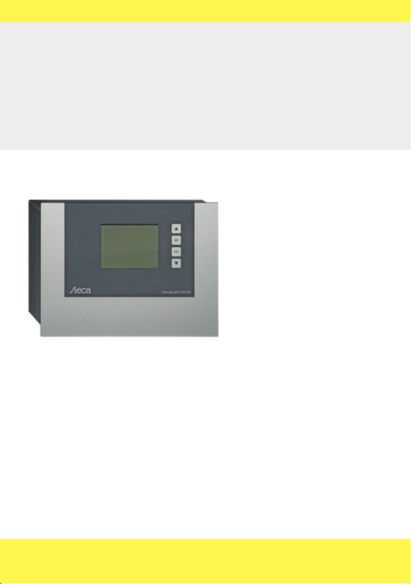
Fernanzeige • remote indication
télé-affichage • display remoto
StecaGrid Vision
Handbuch • Manual • Manuel • Manuale
DE EN FR IT
734.144 | Z04 | 2012-11-22
Änderungen aufgrund technischer Verbesserungen vorbehalten!
Page 2

EN
Contents
1 General safety instructions .................................... 30
2 Proper usage .......................................................... 30
3 About this manual ................................................. 31
3.1 Contents ................................................................... 31
3.2 Target group ............................................................. 31
3.3 Symbols and markings .............................................. 31
4 Scope of delivery ...................................................32
5 Installation ............................................................ 33
5.1 Mounting method .................................................... 33
5.2 Deinstallation ............................................................ 33
6 Structure and function ..........................................34
6.1 Structure ................................................................... 34
6.2 Function.................................................................... 35
7 Commissioning ...................................................... 36
7.1 Power supply ............................................................ 36
7.2 Data connection ....................................................... 36
7.3 Basic settings ............................................................ 37
8 Switching on ......................................................... 40
8.1 System daily yield ..................................................... 40
8.2 Inverter daily yield ................................................... 40
9 Main menu ............................................................. 41
9.1 Querying outputs and yields ..................................... 41
9.2 Settings .................................................................... 44
9.3 Alarm ........................................................................ 46
9.4 Information ............................................................. 47
9.5 Errors/Warnings ....................................................... 48
10 Maintenance .......................................................... 48
11 Messages ...............................................................49
11.1 Error messages ......................................................... 49
11.2 Settings screens ........................................................ 52
12 Technical data ........................................................54
13 Legal guarantee ..................................................... 55
13.1 Defects in materials and workmanship ..................... 55
13.2 General information ................................................. 55
13.3 Guarantee exclusion clause ....................................... 55
14 Exclusion of liability ............................................... 56
15 Contact ..................................................................56
16 Notes ...................................................................... 56
734.144 | Z04 | 2012-11-22
29
Page 3

1 General safety instructions
• This document is part of the product.
• Install and use the device only after reading and understanding this document.
• Keep this document in a safe place for the entire service life of the device. Pass this
document on to subsequent owners or operators of the device.
• Adhere to all safety instructions. Consult (further) professional personnel in the
event of any ambiguities.
• Only qualified electricians may install, commission, repair or deinstall this device.
• As soon as it becomes evident that safe operation is no longer possible (e.g. if there
is visible damage), remove the device from the grid immediately.
• Observe the prescribed conditions of use, see Section 12, p. 54.
• Factory labels and markings must never be altered, removed or rendered unreadable.
• This device is not intended for children or persons with physical, sensory, or mental
disabilities.
2 Proper usage
The StecaGrid Vision remote display, subsequently referred to as the remote display, is
exclusively designed for connection to the following inverters:
• StecaGrid 1800/2300/3010/3000/3600/4200 and StecaGrid 2020
• StecaGrid 8000 3ph/10000 3ph
• StecaGrid 8000+ 3ph/10000+ 3ph
The remote display allows setting of inverter parameters and display of inverter operating data.
EN
30
734.144 | Z04 | 2012-11-22
Page 4
EN
3 About this manual
3.1 Contents
This manual describes the installation, commissioning, operation and deinstallation of
the remote display. The instructions of the respective manufacturer(s) must be observed
for all components connected to the remote display.
3.2 Target group
The target group of this document are:
• technical professionals installing, connecting, commissioning and de-installing the
device.
• end users reading operating data from the device.
Technical professionals are, for example:
• Persons who have the knowledge of terminology and the skills necessary for setting
up and operating photovoltaic systems.
• Persons who have the necessary training, knowledge and experience, and knowledge of the applicable regulations in order to evaluate and recognise the dangers
inherent in the following work:
– Installation of electrical equipment
– Production and connection of data communication cables
– Production and connection of mains grid power supply cables
3.3 Symbols and markings
3.3.1 Warning and operating notes
Warning and operating notes commence with a combination of a symbol and a keyword, followed by the explanation.
Symbols
Symbol Description
Tab. 1: Symbols used for warning and operating notes
Keywords
Keyword Description
Danger Immediate danger of death or serious bodily injury
Warning Possible danger of death or serious bodily injury
Caution Possible danger of light or medium bodily injury
Attention Possible damage to property
Note Note on operation or use of the manual
Tab. 2: Keywords used for warning and operating notes
Example
734.144 | Z04 | 2012-11-22
Danger
Risk of death by electrocution! All work must be performed with the inverter removed
from all power sources.
General danger warning
Danger from electricity
31
Page 5
3.3.2 Labels used in the text
Label Description
• List
1., 2., 3. ... Several steps in a sequence whereby the sequence must be followed
✔
italics • Emphasis, light
bold Emphasis, heavy
serif Designation of product elements, e.g. buttons, switches, displays
<italics> Variable, placeholder
Tab. 3: General labels used in the text
Single step
Condition for performing an action
• Cross-reference
4 Scope of delivery
• 1 x StecaGrid Vision remote display
• 1 x mains adapter plug
• 2 x COMBICON plug connector: 2-pole, 3-pole
• 1 x HARTING PushPull RJ45 10G, no. 09 45 145 1560: push-pull locking mechanism,
can be wired without tools
• 3 x dowels, 6 mm with screws
EN
32
734.144 | Z04 | 2012-11-22
Page 6
EN
5 Installation
5.1 Mounting method
Caution
• Risk of electrical shock and fire if mounted in a damp environment!
The mounting location must conform to the protection degree of the device; see
Section 12, p. 54.
• Danger of bodily injury and damage to the casing when drilling!
Do not use the casing as a drilling template.
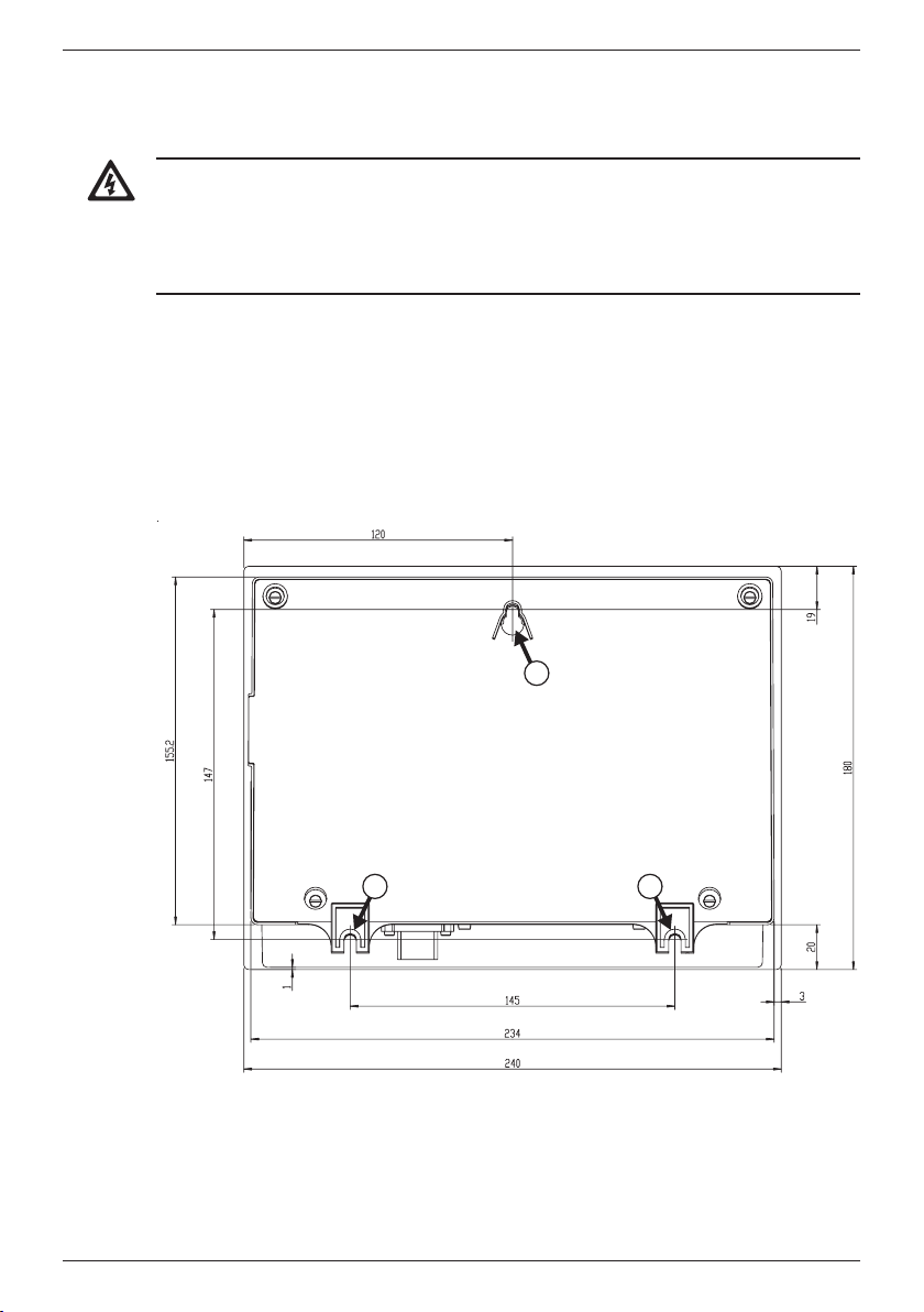
1. Choose a suitable installation site.
2. Drill the upper fastening hole.
3. Screw in the screw.
4. Hang the case in the recess and align it correctly.
5. Mark the position of the lower fastening holes / .
6. Remove the case.
7. Drill the lower fastening holes.
8. Hang the casing in the recess .
9. Screw the case firmly using the lower fastening holes / .
1
5.2 Deinstallation
To deinstall the remote display, follow the installation instructions in the reverse
order. If necessary re-terminate the data bus.
734.144 | Z04 | 2012-11-22
2
3
33
Page 7
6 Structure and function
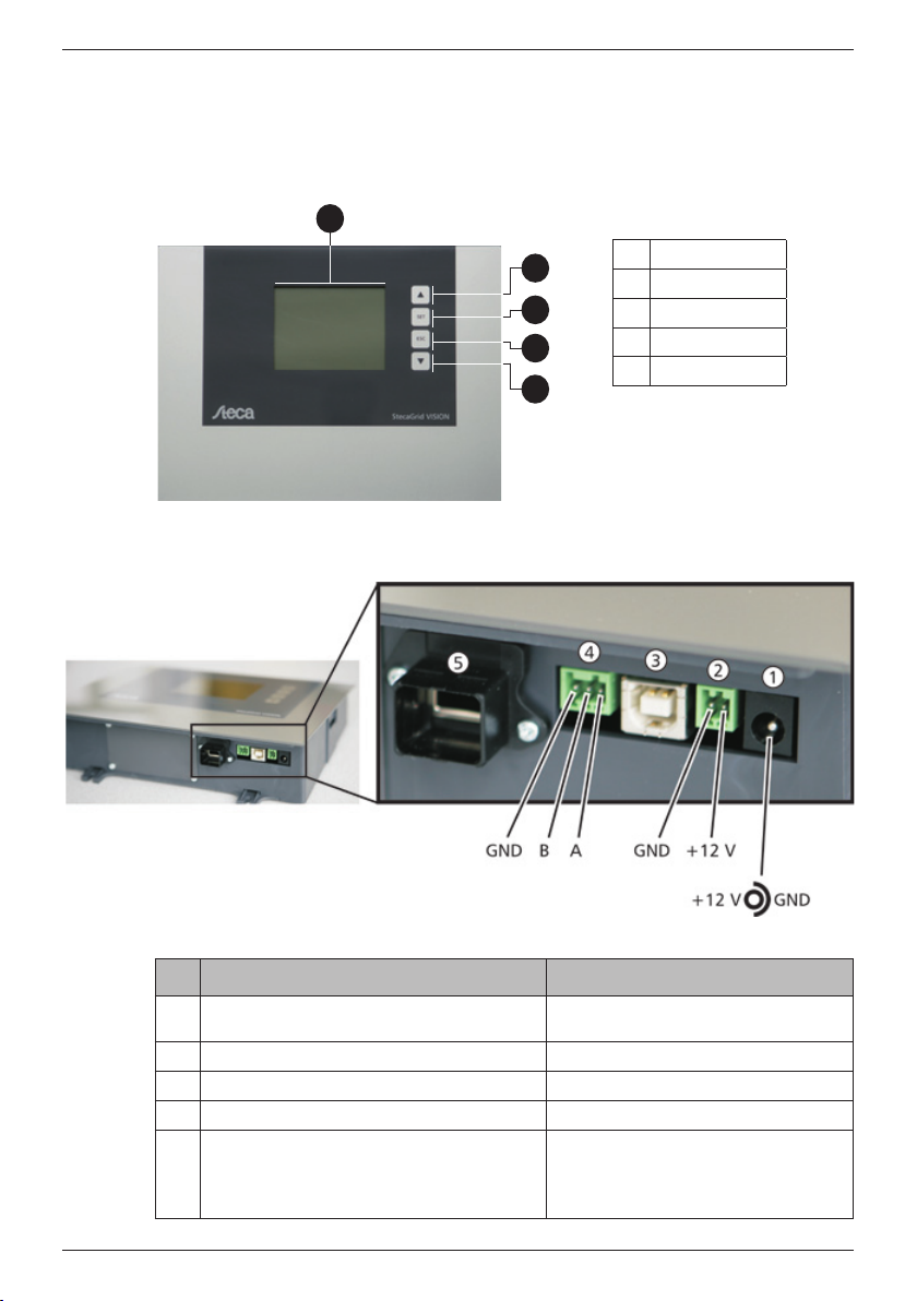
6.1 Structure
6.1.1 Front
1
Fig. 1: Front with display and operating buttons
6.1.2 Connections on the underside
EN
Display
2
3
4
5
UP button
SET button
ESC button
DOWN button
34
Fig. 2: Connections on the underside
No. Interface Description
Connection for mains adapter plug for mains adapter plug supplied with
COMBICON DC interface for an external power supply
USB connection, for internal servicing only –
COMBICON RS485 interface for external data cable
RS485 interface with RJ45 socket and
external housing
the device
pin assignments (connection pin
signal):
1 A; 2 B; 8 GND
3 ... 7 not used
734.144 | Z04 | 2012-11-22
Page 8
EN
6.1.3 Cable connections
Up to 20 inverters can be connected to the remote display. Communication between the
remote display and the inverters takes place using a wired connection over an RS485
bus. More information is provided in the inverter manual.
6.2 Function
6.2.1 Operating buttons
Button Function
(UP button)
SET • enters a selected submenu
ESC • jumps one menu level upwards
(DOWN but-
ton)
Tab. 4: Functions of the operating buttons
6.2.2 Settings
• Date / time of the internal clocks of the remote display and inverters
• Country: Setting the country also defines the local regulations for feeding electric-
ity into the mains grid. This setting affects all connected inverters and, due to mains
grid feed safety regulations, this setting can be performed only once.
• Addresses of the inverters
• Language used for displaying text messages in the remote display
• Contrast / illumination of the display
• scrolling up through the menu
• increases a selected value
• confirms an entered setting
• discards an entered setting
• scrolling down through the menu
• decreases a selected value
6.2.3 Display
The following information stored in the inverters can be read on the remote display:
• Output and yields
– of all inverters
– of individual inverters
• Numerical and graphical display
734.144 | Z04 | 2012-11-22
35
Page 9
7 Commissioning
Note
7.1 Power supply
No specific sequence needs to be followed when connecting the power supply to the
remote display and the data cables between the remote display and the inverters.
The power supply must satisfy the following conditions:
✔ Rated voltage: 12 V ± 20 %
✔ Maximumpowerconsumption:≤4W
The mains adapter plug supplied with the device satisfies these requirements.
Connecting the power supply
EN
Attention
Danger of damage or malfunction.
The COMBICON plug supplied may only be connected by qualified electricians.
Connect the mains adapter plug to the DC socket
or
connect an external power supply to the COMBICON socket using the COMBICON
plug provided.
Note
The power supply inputs are reverse-polarity protected. If the external power supply is
connected with reverse polarity then the display remains dark.
7.2 Data connection
Connect the remote display to the first inverter using the cable provided or an alter-
native cable. More information is provided in the inverter manual.
Attention
The external housing for the RJ45 socket (
with the HARTING PushPull RJ45 10G plug provided. Standard RJ45 plugs can jam.
Remove the external housing if you wish to insert a standard RJ45 plug. To do this,
remove the two screws fastening the external housing.
in Fig. 2, p. 34) is only suitable for use
36
734.144 | Z04 | 2012-11-22
Page 10
EN
7.3 Basic settings
A number of basic settings must be performed on the newly connected remote display.
This is done via a guided commissioning process. The following applies:
• The guided commissioning process starts when:
– basic settings have not yet been performed and the remote display is switched
on for the 1st time.
– the remote display has been without power for longer than 2 days.
• Basic settings are performed for both the remote display and the inverters.
• A unique address from 1 – 20 must be set at every inverter. Each address may
only be assigned once in the system. More information is provided in the inverter
manual.
The following section describes the display messages during the guided commissioning
process.
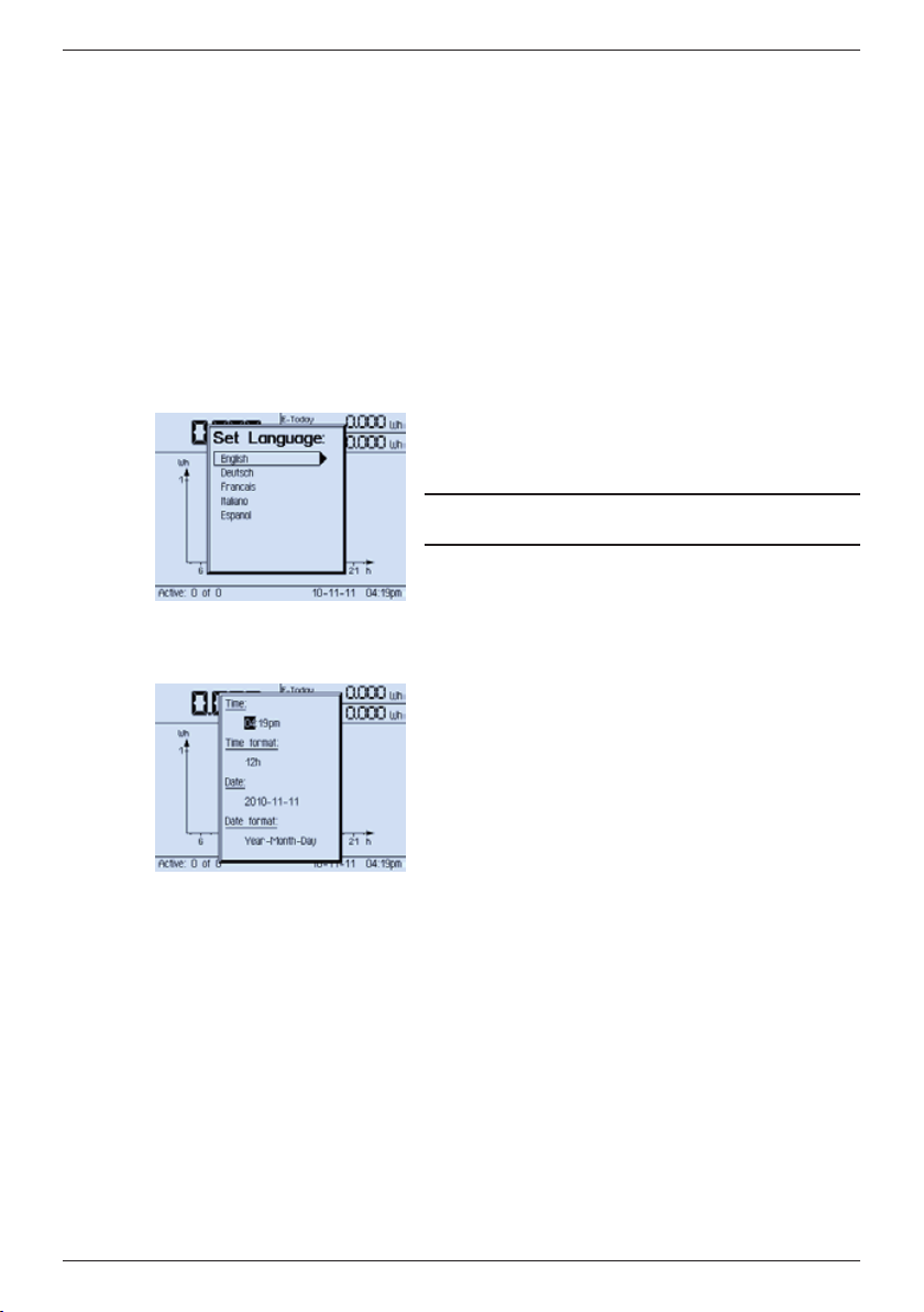
7.3.1 Language
7.3.2 Time & date
Use the UP and DOWN buttons in the Set Language
window to select the correct language and confirm
this selection with the SET button.
Note
The languages are displayed in the country language.
The time, time format, date and date format must be
set in the next step.
Use the UP and DOWN buttons to browse through
the values and select the desired value using the SET
button. Pressing the SET button also brings you to the
next value to be set.
Once you have set all values you must press the SET
button once more to save these settings.
The values appear in the following sequence:
Time: hours
Time: minutes
Time: format (12 / 24)
Date: year
Date: month
Date: day
Date: format (Day Month Year; Month Day Year; Year
Month Day)
734.144 | Z04 | 2012-11-22
37
Page 11
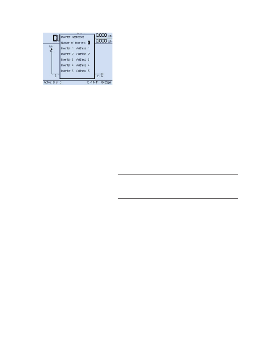
7.3.3 Entering the number of inverters and the addresses of the
inverters
In the next step you must enter the number of inverters and the addresses of the inverters in a list:
1. Use the UP and DOWN buttons to select the number of inverters.
2. Confirm this by pressing the SET button.
The address list now contains the selected number
of inverters and the address field of inverter 1 is
active.
3. Use the UP and DOWN buttons to set one of the
inverter addresses.
4. Confirm this by pressing the SET button. The address field of inverter 2 is now active (if present).
5. Repeat steps 3. and 4. above until all inverter addresses have been entered. The next step is:
— Setting the country (see Section 7.3.4; you
may need to wait a few seconds at the System
daily yield screen).
— Jump into the address list to the first incor-
rect inverter entry if duplicate addresses have
been assigned.
You also need to go through the entire address
list from the first incorrect inverter entry to the
end of the list.
Note
After step 2., the list entries are not yet specifically
assigned to actual physical inverters. This occurs in
step 4.
EN
38
734.144 | Z04 | 2012-11-22
Page 12
EN
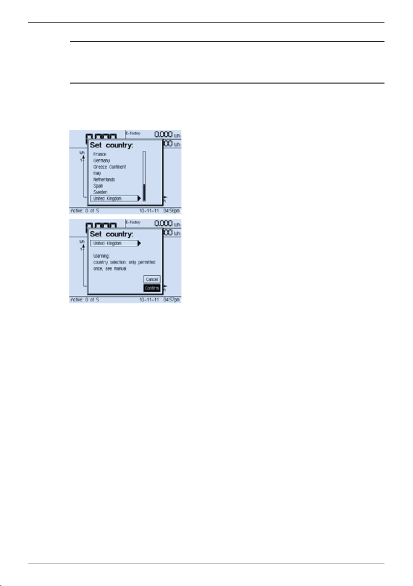
7.3.4 Country setting
Note
Setting the country also defines the local regulations for feeding electricity into the
mains grid. In accordance with the grid feed safety regulations, the country can only be
set once and cannot be subsequently changed.
The remote display queries all inverters for the countries that are currently set and all
countries that are supported. Four possible cases can occur:
Case 1: No inverters have a country set (standard)
1. Use UP / DOWN to select a country (Fig. left).
Note: If your country is not displayed then select
a country with values as close as possible to your
country; see the country table in the inverter
manual.
2. Press SET. The confirmation prompt is displayed.
3. Select Confirm (Fig. left).
4. Press SET. The System daily yield screen is displayed.
Case 2: Different countries are set in the inverters
See Section 11.2.4, p. 53 onwards.
Case 3: No common country selection is available in the inverters
See Section 11.2.4, p. 53 onwards.
Case 4: A country has been preset in the inverters at the factory.
If a country has been preset at the factory you are not asked to set the country (country
selection screen is not displayed).
Check that the correct country is set in the Settings / Country screen. If the correct
country is not set then notify a service technician in order to reset the country setting.
734.144 | Z04 | 2012-11-22
39
Page 13
8 Switching on
8.1 System daily yield
EN
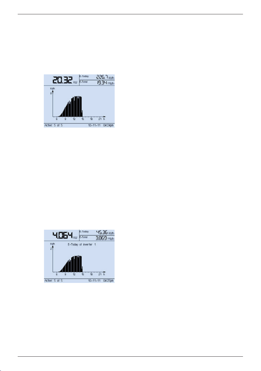
When the power supply is connected to the remote
display it first displays the start logo and then the
System daily yield screen.
If a malfunction exists then the Steca logo remains
visible.
The System daily yield view provides an overview of
the current state of all inverters. The current summed
output of all inverters is displayed at the upper left of
the screen. The yield for the current day (E-Today) and
the total yield (E-Total) are displayed at the upper right
of the screen. The yield curve for the current day is
displayed in the middle of the screen.
The yield curve allows you to see what yields were
achieved at what times of the day. At the lower left
of the screen is an indication of how many of the
addressed inverters are currently active and feeding
electricity into the mains grid. The current date and
time are displayed at the lower right of the screen.
An hourglass symbol is displayed if not all values are
available because the remote display has not yet queried all values from all inverters.
An appropriate message is displayed if communication
with one or more inverters is not possible.
If a device, e.g. a PC, is connected to the USB interface
of the remote display then the message USB mode ac-
tive is displayed. The remote display cannot query any
values from the inverters while the device is connected
to the USB port.
8.2 Inverter daily yield
40
You can display the daily yield of a selected inverter.
From the System daily yield screen, use the UP and
DOWN buttons to select the Inverter daily yield
screen and press SET. You can now use the UP and
DOWN buttons to select each inverter in turn.
The particular inverter selected is displayed in the daily
curve.
If the selected inverter cannot be queried then the
message Inverter not available is displayed.
If a device, e.g. a PC, is connected to the USB interface
of the remote display then the message USB mode ac-
tive is displayed. The remote display cannot query any
values from the inverters while the device is connected
to the USB port.
Pressing the ESC button returns you to the System
screen.
734.144 | Z04 | 2012-11-22
Page 14
EN
9 Main menu
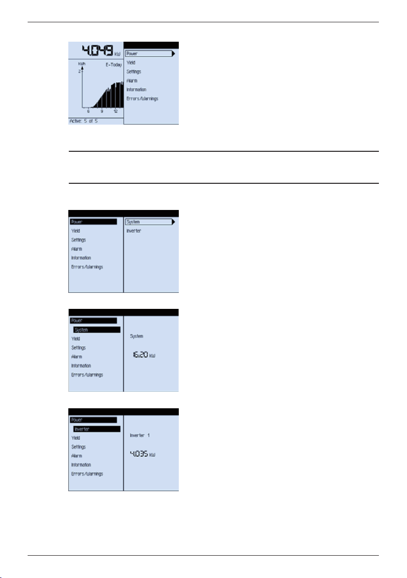
Pressing the SET button in the System daily yield or
Inverter daily yield screens will bring you to the main
menu. You navigate through the menu entries using
the UP and DOWN buttons. Pressing the SET button
displays the submenu of the currently selected main
menu entry. Pressing the ESC button brings you back
to the menu level above. Pressing the ESC button
in the main menu will return you to the System or
Inverter screen.
9.1 Querying outputs and yields
Note
9.1.1 Power
In a system with many inverters the large data volume can result in delays of up to 30 s
when switching between the various displays described below.
The Power submenu allows you to display the output
of the entire system or individual inverters 1).
1)
Only in systems with more than 1 inverter
734.144 | Z04 | 2012-11-22
System
This screen shows the total output of the system by
summing the output of all inverters. This corresponds
to the output value displayed in the System screen.
Inverter
This screen shows the output of the selected inverter.
You can now use the UP and DOWN buttons to select
each inverter in turn.
41
Page 15
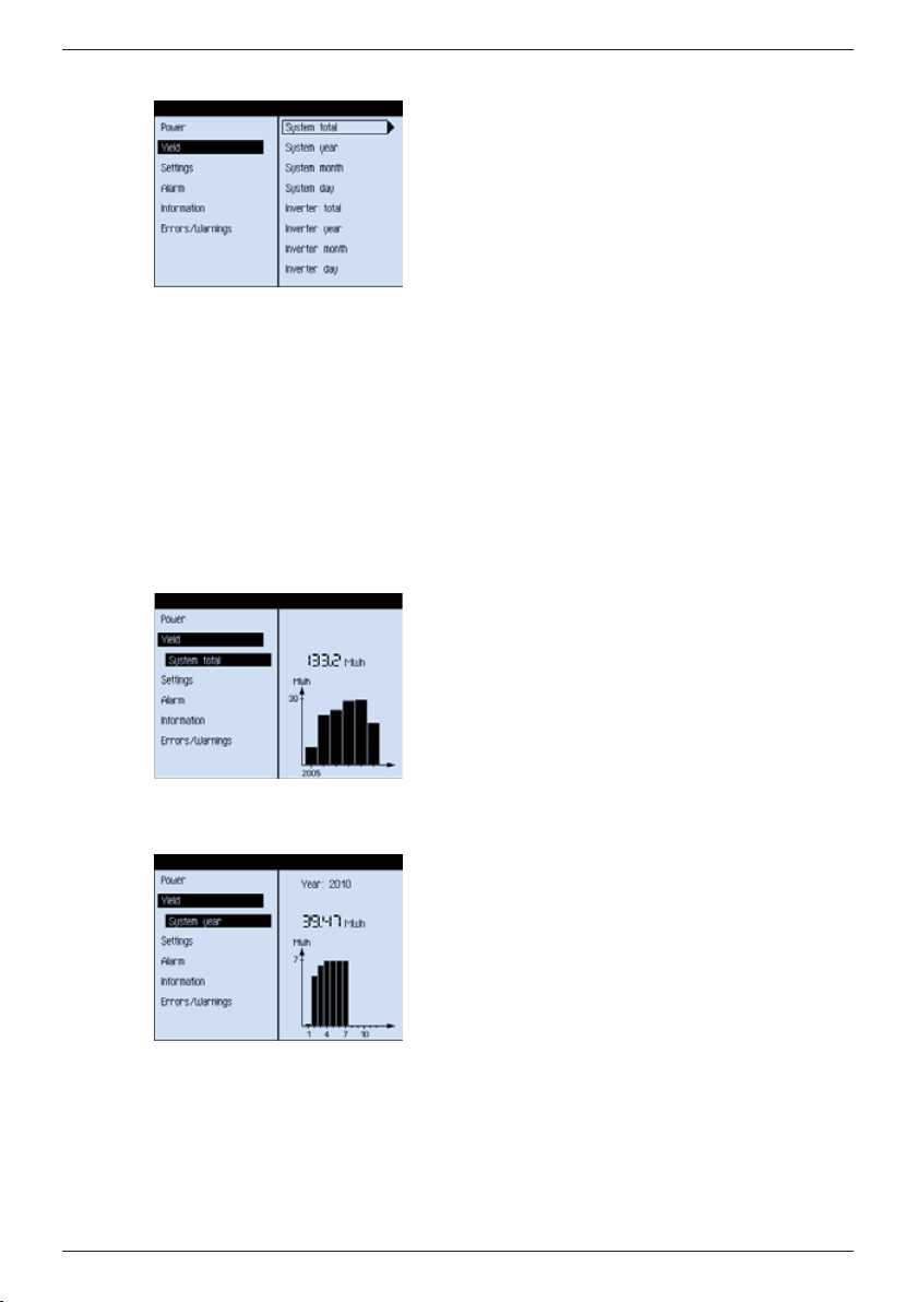
9.1.2 Yield
EN
The Yield submenu allows you to display the yield of
the entire system or individual inverters.
You can select different time periods:
• System total
• System year
• System month
• System day
• Inverter total
• Inverter year
• Inverter month
• Inverter day
1)
1)
1)
1)
An hourglass symbol is displayed if not all information
is available because the remote display has not yet
queried all values from all inverters.
An appropriate message is displayed if communication
with one or more inverters is not possible.
If a device, e.g. a PC, is connected to the USB interface
of the remote display then the message USB mode ac-
tive is displayed. The remote display cannot query any
values from the inverters while the device is connected
to the USB port.
1)
Only in systems with more than 1 inverter
System total
This menu item allows the annual total yield for all
inverters to be displayed as a bar chart. The following
applies:
• Each bar represents one year.
• The diagram begins with the first year in which
a yield was measured and ends with the current
year.
• Up to 30 bars / years can be displayed at the same
time.
• The total yield over all years is displayed above the
bar chart.
System year
This menu entry displays the total yield of all inverters
for the current year. The yields for each month of the
current year are displayed as a bar chart. You can now
use the UP and DOWN buttons to browse through the
last 20 years.
42
734.144 | Z04 | 2012-11-22
Page 16
EN
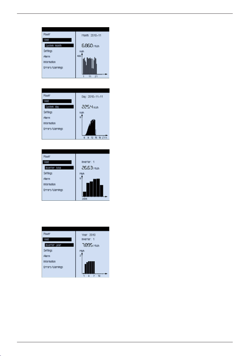
System month
This menu item displays the summed yield of all inverters for the selected month. The yields for each day of
the selected month are displayed as a bar chart. The
number of days in the month are taken into account
(30, 31 or 28/29). You can use the UP and DOWN buttons to browse through the last 12 months. Changing
from January to December or vice versa automatically
selects the previous or next year.
System day
This menu item displays the summed yields of all
inverters for the selected day. The yield over the day
is displayed with a bar chart. You can use the UP and
DOWN buttons to browse through the last 7 days.
Reaching the end of each month or year automatically
brings you to the next month or year.
Inverter total
This menu item displays the total annual yield of the
selected inverter as a bar chart. The following applies:
• Each bar represents one year.
• The diagram begins with the first year in which
a yield was measured and ends with the current
year.
• Up to 30 bars / years can be displayed at the same
time.
• The total yield over all years is displayed numeri-
cally above the chart.
• You can use the UP and DOWN buttons to select
the next or previous inverter.
Inverter year
This menu item displays the yield of the selected
inverter for the current year. The yields for each month
of the current year are displayed as a bar chart. You
can now use the UP and DOWN buttons to select each
inverter in turn.
734.144 | Z04 | 2012-11-22
43
Page 17
9.2 Settings
EN
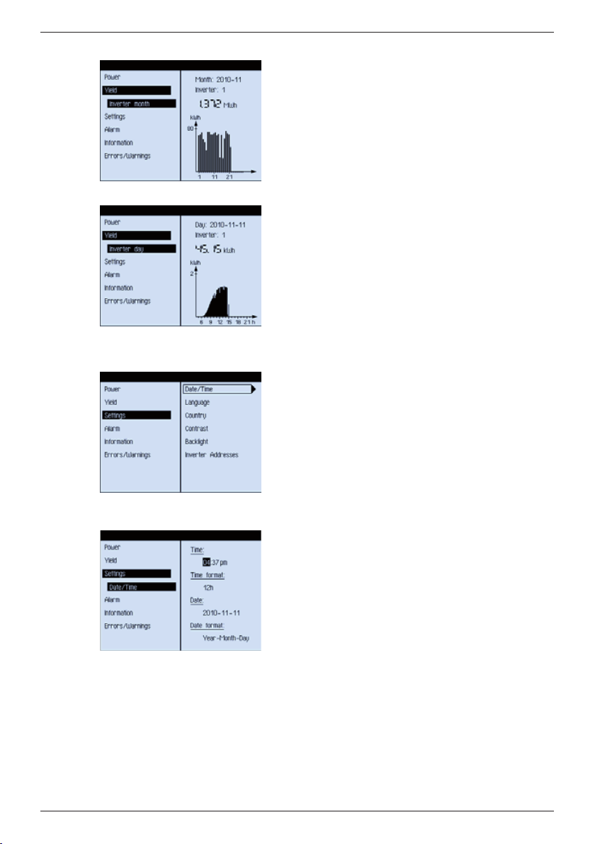
Inverter month
This menu item displays the yield of the selected
inverter for the current month. The yields for each day
of the selected month are displayed as a bar chart. The
number of days in the month are taken into account
(30, 31 or 28/29). You can now use the UP and DOWN
buttons to select each inverter in turn.
Inverter day
This menu item displays the yield of the selected
inverter for the current day. The yield over the day is
displayed with a bar chart. You can now use the UP
and DOWN buttons to select each inverter in turn.
The Settings submenu allows you to change the following system settings.
• Date and time
• Language
• Country
• Contrast
• Backlight
• Inverter Addresses
44
Date/Time
This menu item allows you to set the time, the time
format, the date and the date format.
Use the UP and DOWN buttons to browse through
the values and select the desired value using the SET
button. Pressing the SET button also brings you to the
next value to be set.
Once you have set all values you must press the SET
button once more to save these settings.
The values appear in the following sequence:
Time: hours
Time: minutes
Time: format (12 / 24)
Date: year
Date: month
Date: day
Date: format (Day Month Year; Month Day Year; Year
Month Day)
734.144 | Z04 | 2012-11-22
Page 18
EN
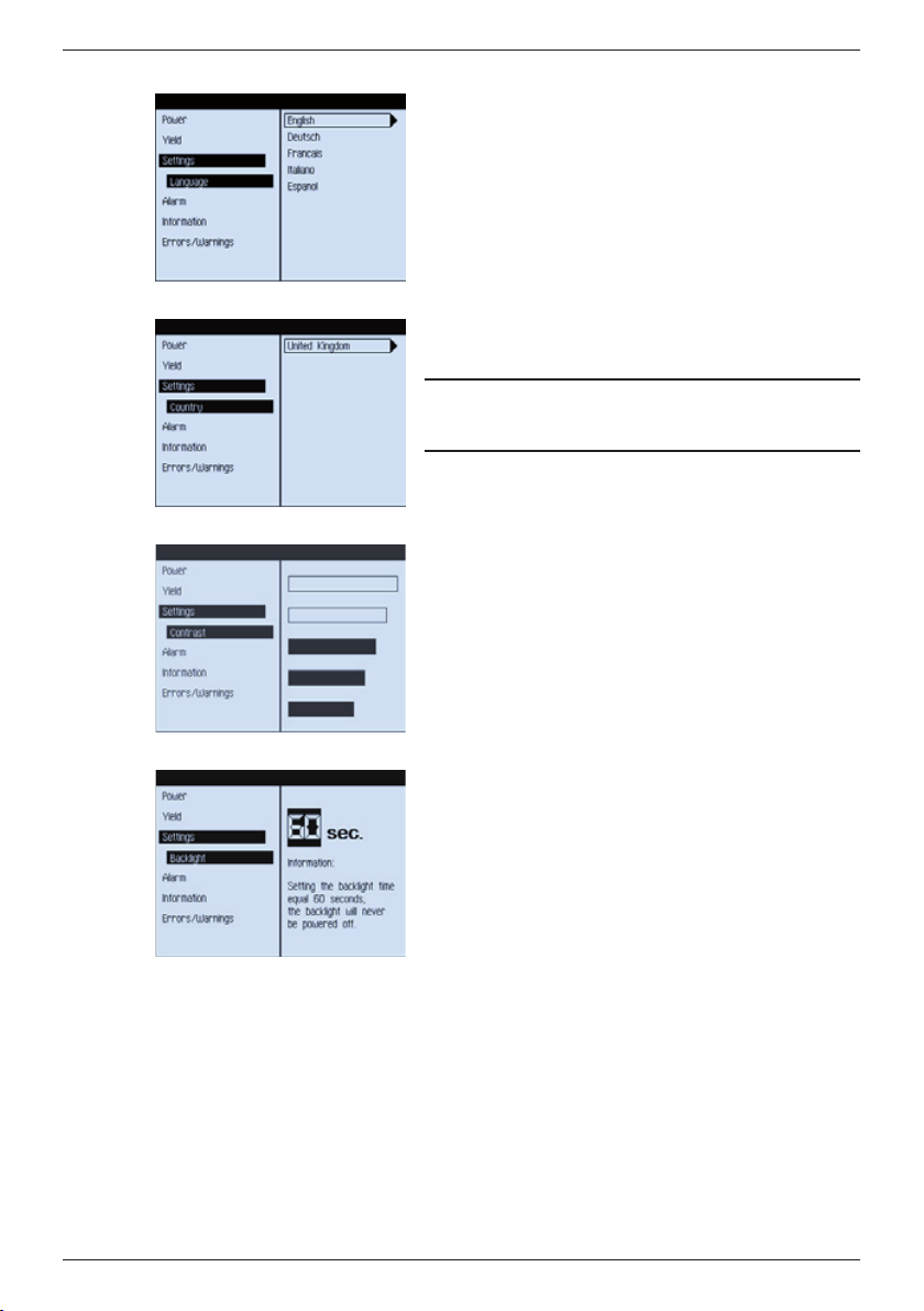
Language
A list of languages supported by the remote display
is displayed. The current language is selected. Use the
UP and DOWN buttons to browse through the languages and select one of these using the SET button.
Country
The country currently set for the connected inverters is
displayed.
Note
If this view appears then the country is correctly set
and can no longer be changed.
Contrast
This menu item allows you to set the display contrast to one of 5 levels. The selected contrast level is
displayed graphically. Use the UP and DOWN buttons
to select a different level. The modified setting is
immediately visible so you can see if the new setting
is correct. Pressing the SET button confirms the new
setting. Pressing ESC discards the new setting and the
display returns to the previous contrast setting.
734.144 | Z04 | 2012-11-22
Backlight
This menu item allows you to set a timer defining
how long the display illumination remains switched
on when no commands are entered. This timer is reset
each time a button is pressed.
You use the UP and DOWN buttons to set a period
defined in seconds and then confirm this value by
pressing the SET button. A value of 60 sec. causes the
display illumination to remain on permanently.
45
Page 19
9.3 Alarm
This menu item allows you to define how (Settings) and at what values (Thresholds) the
remote display should provide notification in the case of an alarm.
EN
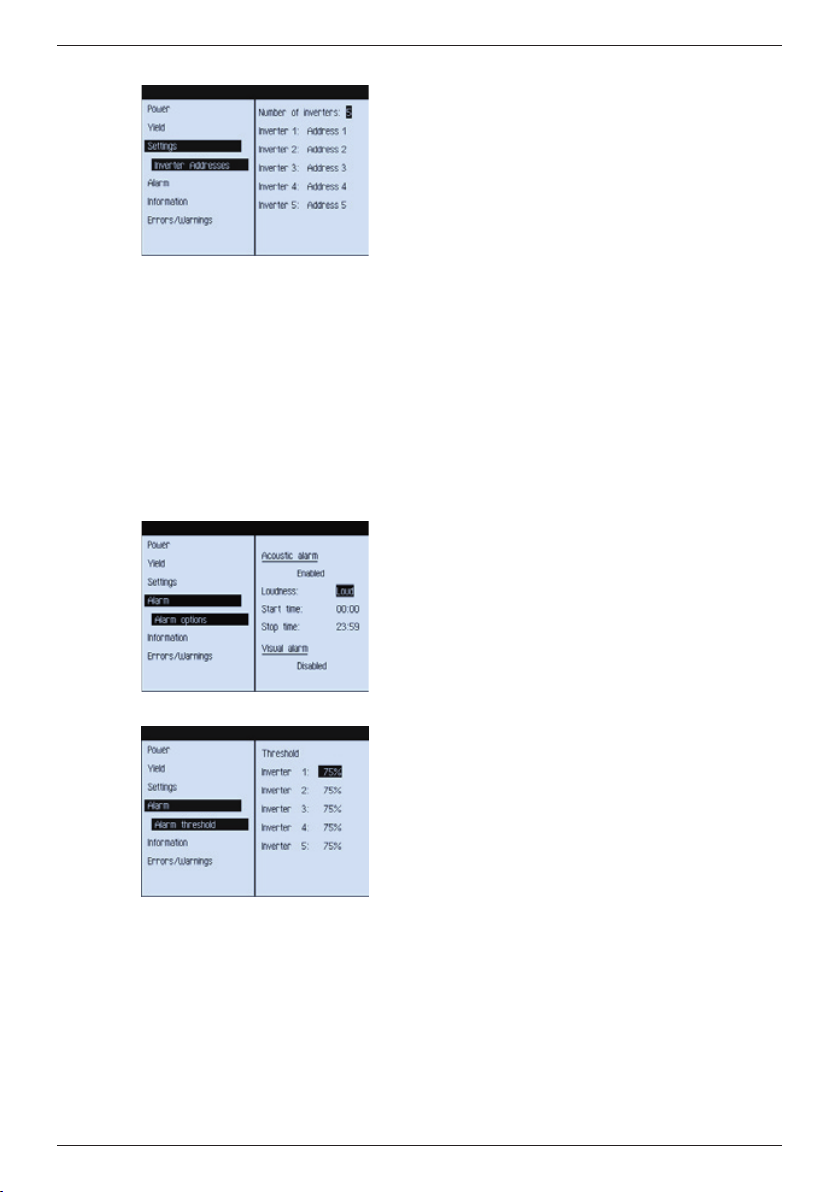
Inverter Addresses
This menu item allows you to set the number of connected inverters and define their individual addresses.
Use the UP and DOWN buttons to set the desired
address value. Pressing the SET button confirms the
value and moves to the next setting.
The number of inverters must be set first. After this
you can set the addresses of each inverter. The number
of displayed inverters is the same as the number of
defined inverters. If a duplicate address is entered then
a warning is displayed at the lower edge of the screen.
Once you have set all values you must press the SET
button once more to save these settings.
If a duplicate address still exists at this time then the
first inverter with a duplicate address is displayed so
that you can directly change this address to a unique
value.
Settings
The following settings are possible for acoustic and
visual alarms:
Acoustic alarm (= permanent tone sequence)
• Enabled / Disabled
• Volume: Quiet / Normal / Loud
• Alarm period per day: Start time / Stop time
Visual alarm (= blinking display illumination)
Enabled / Disabled
46
Thresholds
If an inverter drops below its threshold value then a
low yield alarm is triggered. The threshold value is defined as a percentage value of the average daily yield
over all inverters.
734.144 | Z04 | 2012-11-22
Page 20
EN
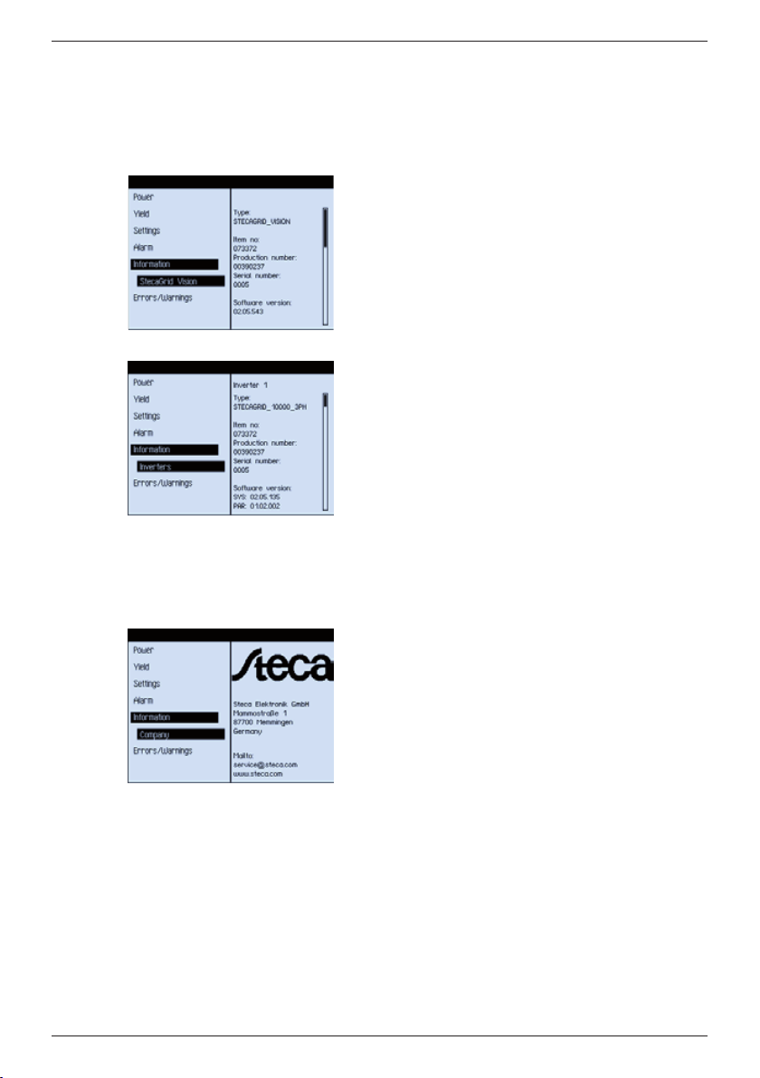
9.4 Information
This menu item provides product information on:
• Remote display
• Inverter
• Manufacturer
Remote display
You can display the following information relating to
the remote display:
• Type designation
• Item number
• Production number
• Serial number
• Software version
• Hardware version
1)
Inverter
You can display the following information relating to
the inverters:
• Inverter number (not the address!)
• Type
• Item number
• Production number
• Serial number
• Software version:
— Assembly SYS
— Assembly CommAdapt
• Hardware version 1):
— Assembly SYS
— Assembly CommAdapt
SET jumps to the next inverter.
Company
This item displays the Steca contact information.
734.144 | Z04 | 2012-11-22
1)
For display use the DOWN button to scroll down.
47
Page 21
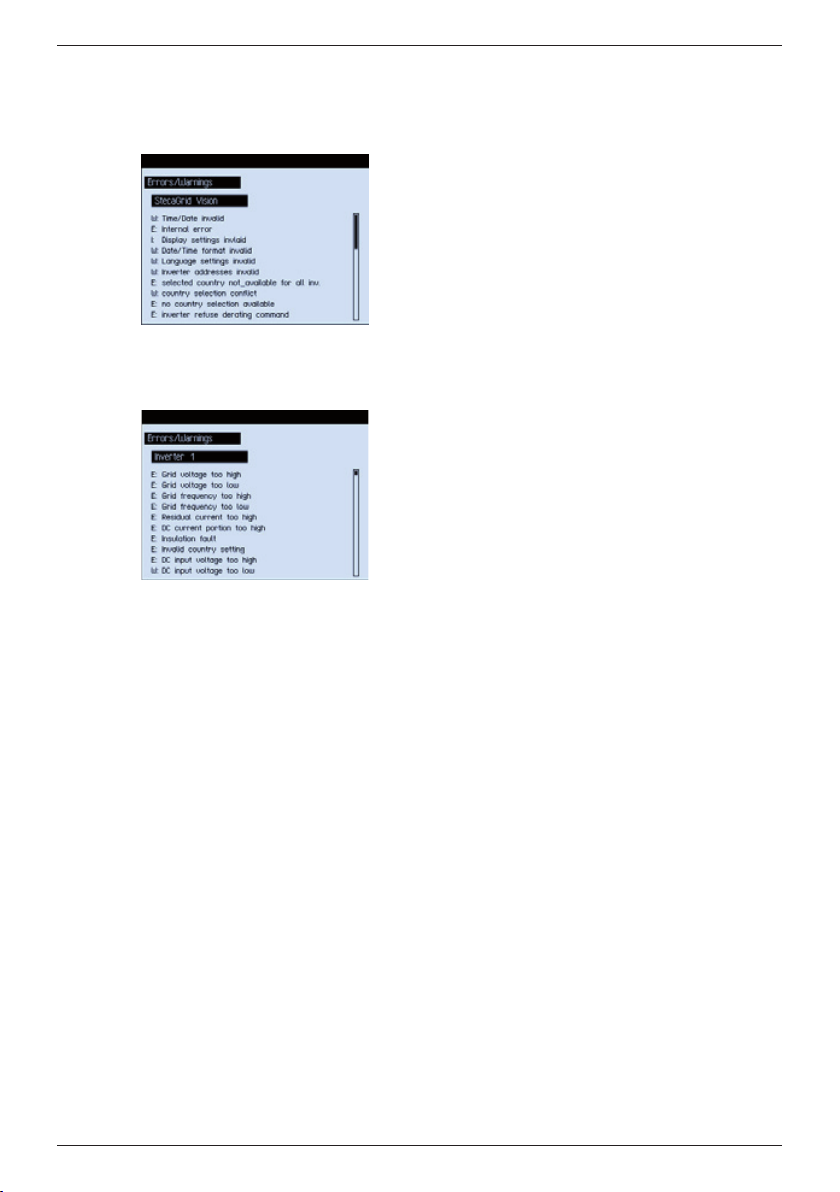
9.5 Errors/Warnings
This menu item allows you to display the last errors logged for the System or Inverter.
9.5.1 System
9.5.2 Inverter
EN
All currently logged remote display errors are shown
here in a list. Both confirmed and non-confirmed errors are listed. You can use the UP and DOWN buttons
to scroll through the list.
All currently logged errors for the selected inverter
are shown here in a list. Both confirmed and nonconfirmed errors are listed. You can use the UP and
DOWN buttons to scroll through the list.
You use the SET button to select the next inverter.
After the last inverter the list jumps back to the first
inverter.
10 Maintenance
The remote display is maintenance free.
48
734.144 | Z04 | 2012-11-22
Page 22
EN
11 Messages
11.1 Error messages
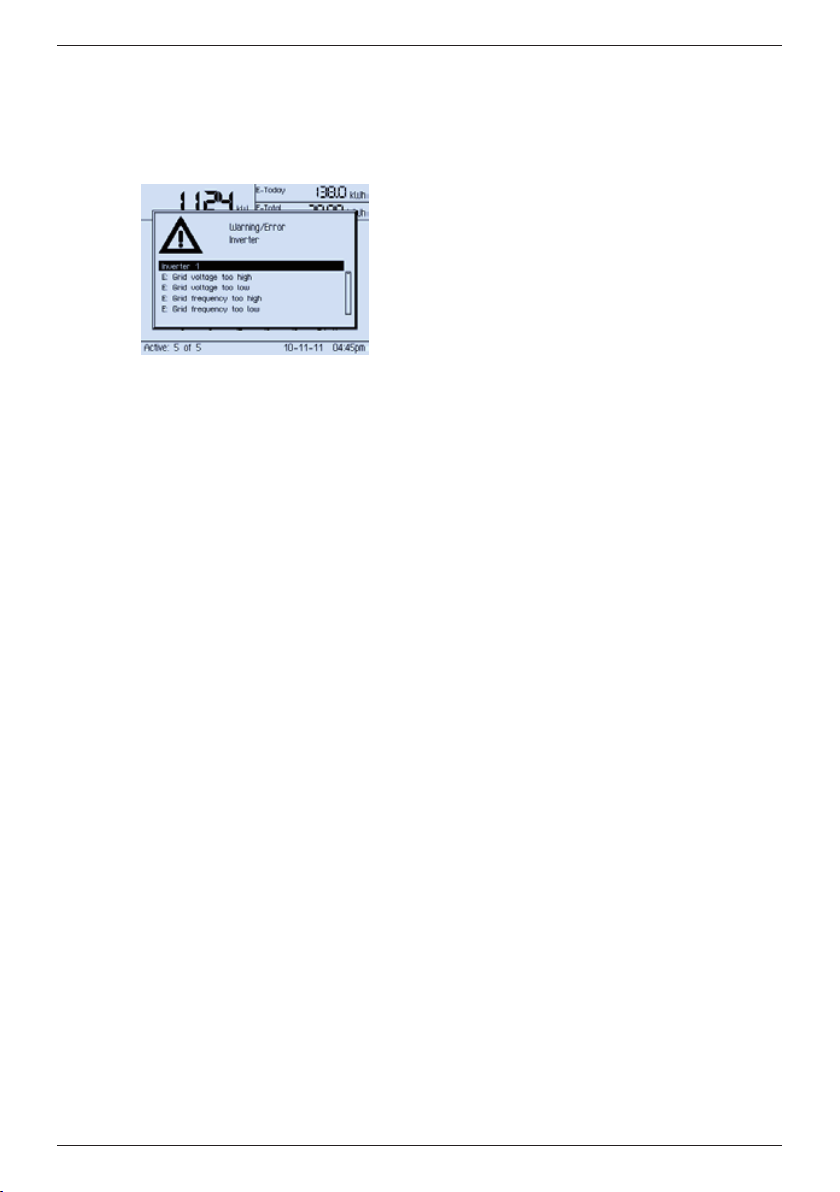
Error messages are generated either by the inverters or the remote display and are
displayed as follows:
11.1.1 Error message types
There are 3 types of error message:
• Type Information I
The inverter has detected an error that does not affect the feed-in process. The user
must take action to correct the error.
• Type Warning W
The inverter has detected an error that may result in reduced yields. It is highly recommended that you correct the cause of the error.
• Type Error E
The inverter has detected a serious error. No electricity is being fed into the mains
grid. The user must inform the customer service.
11.1.2 Handling of error messages
• Messages relating to minor errors disappear as soon as the error is no longer present.
• Serious errors are (permanently) displayed until they are confirmed by pressing the
SET button; see the right column in Tab. 5, p. 50 onwards.
• If an already confirmed error recurs then it is displayed again.
734.144 | Z04 | 2012-11-22
49
Page 23
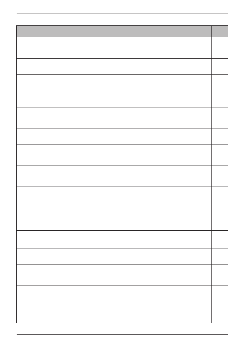
11.1.3 Inverter error messages
Error message Description Type
Grid voltage too
high
The mains voltage of one or more phases at the inverter exceeds the permissible value. The inverter must not feed into the grid.
Contact your installer.
EN
Perma-
nent
E
Grid voltage too
low
The mains voltage of one or more phases at the inverter is less than the
permissible value. The inverter must not feed into the grid.
Contact your installer.
Grid frequency too
high
The grid frequency at the inverter is greater than the maximum permissible
value. The inverter must not feed into the grid.
Contact your installer.
Grid frequency
too low
The grid frequency at the inverter is less than the minimum permissible
value. The inverter must not feed into the grid.
Contact your installer.
Residual current
too high
The residual current flowing from the positive or negative inputs to earth
via the photovoltaic modules exceeds the maximum permissible value. The
inverter must not feed into the grid.
Contact your installer.
DC current portion
too high
The DC current portion fed into the grid by the inverter exceeds the maximum permissible value. The inverter must not feed into the grid.
Contact your installer.
Insulation fault The insulation resistance between the positive or negative input and earth
is less than the permissible value. The inverter must not switch onto the
grid.
Contact your installer.
Invalid country
setting
One or more inverters have an invalid country code. Either no country was
selected during commissioning or differing countries are selected for multiple inverters in the same system. The inverter(s) do not feed into the grid.
Set the correct country code for all inverters as described above.
DC input voltage
too high
The input voltage at the inverter exceeds the permissible value. The inverter
does not feed into the grid.
Switch off the main DC switch of the inverter
1)
and contact your
installer.
DC input voltage
too low
The input voltage at the inverter is less than the permissible value. The
inverter cannot feed into the grid.
Contact your installer.
2)
Internal error
Internal warning
Internal informa-
Contact your installer. E X
3)
Contact your installer. W X
Contact your installer. I X
tion
Derating: Temperature
The inverter cannot feed the grid at full power because the maximum
permissible internal temperature has been reached.
Contact your installer if this warning occurs frequently.
Derating: Average
value after 10
minutes
The inverter cannot or may not feed the grid at full power because the
average output voltage over a period of 10 minutes lies outside the permissible tolerance range.
Contact your installer if this warning occurs frequently.
Derating: External
(e.g. Power Com-
The inverter has received an external signal via the communications interface and is currently feeding the grid at reduced power.
pany)
Derating: Temperature > 30 min
The inverter cannot feed the grid at full power because the maximum permissible internal temperature has been reached. This state has now existed
for more than 30 minutes.
Contact your installer.
E
E
E
E
E
E X
E X
E X
W X
W
W
W
W
50
734.144 | Z04 | 2012-11-22
Page 24
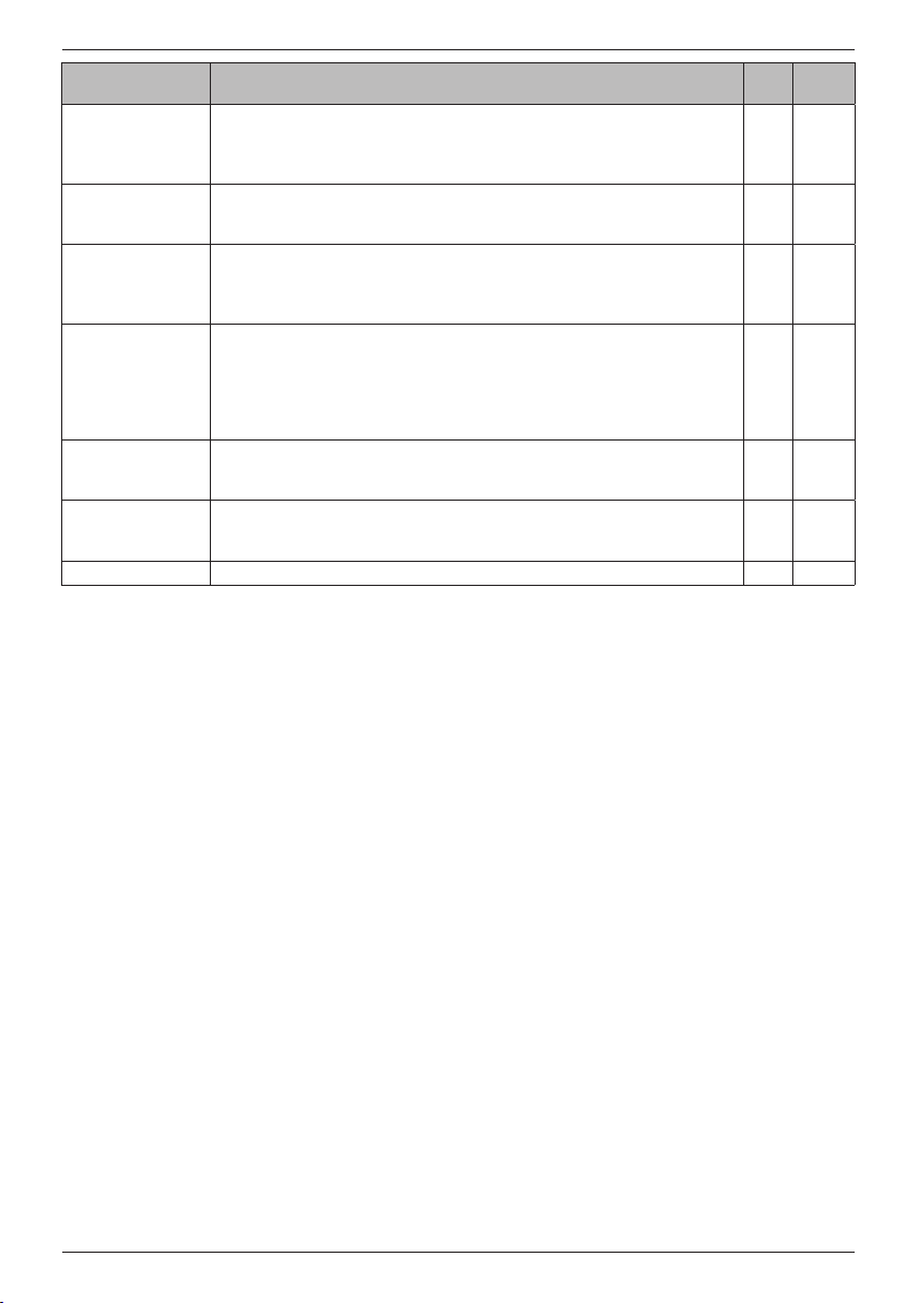
EN
Error message Description Type
Derating: 10
minute average
value > 30 min
The inverter cannot or may not feed the grid at full power because the
average output voltage over a period of 10 minutes has been outside the
permissible tolerance range for over 30 minutes.
Perma-
nent
W
Contact your installer if this warning occurs frequently.
Derating: External
(e.g. Power Company) > 30 min
Time/date not set The time and/or date have not been correctly set at the inverter. The in-
The inverter has received an external signal via the communications interface and is currently feeding the grid at reduced power. This state has now
existed for more than 30 minutes.
W
I X
verter operates without restrictions but the measurements are not correctly
stored in the internal data logger.
Set the date and time.
Option card fault The communications card inserted into the inverter has signalled an error.
I X
The communication to the outside world is possibly interrupted but the
inverter is otherwise operating without restrictions. Check the communication. The communications card may need to be reset (remove the card,
wait a minute and then re-install the card).
Contact your installer if this error message persists.
No grid feed for
24 h
The inverter has fed no power into the grid for at least 24 hours.
Check if the DC switch is switched off or if snow is lying on the solar
E X
modules. If neither is the case then contact your installer.
Grid fault (islanding)
The output voltage between two or more phases of the inverter exceeds
the permissible tolerance range. The inverter switches off for safety rea-
E X
sons.
Self test failed. Contact your installer. E X
Tab. 5: Inverter error messages
1)
Note the number of the affected inverter shown in the error message!
2)
Possible causes:
•Internalcommunicationfault
•Maximumpermittedfeed-intemperatureexceeded
•Conductorbreakageinpowerunit
3)
Startup current limiting is active: 10 minute pause after more than 5 startup attempts in the last
15 minutes.
734.144 | Z04 | 2012-11-22
51
Page 25
11.1.4 Remote display error messages
W: <XX>% below average daily yield
The test for low yields takes place at midnight (0:00 hours) each day. The following applies:
• The daily yield of each inverter is compared to the average daily yield of all inverters.
• An alarm is triggered if an inverter has a yield greater than 0.001 Wh but less than
the defined threshold value.
• <XX> is the percentage value that the inverter yield is below the average yield.
Example:
If an inverter only delivers 75 % of the average daily yield then <XX> has a value of
25 %.
E: 24 h no RS485 communication
The remote display has not been able to communicate with the inverters for more than
24 hours.
E: Shutdown refused
The inverter has refused to obey a shutdown command. The command is generated if a
conflict occurs when setting the country.
E: Country setting refused
The inverter has refused to obey a command to set the country.
Contact your installer.
W: Derating refused
The inverter has refused to obey a command to reduce the output power.
11.2 Settings screens
EN
11.2.1 Language
The language setting is queried during initial commissioning and after an error has been
detected in the internal device storage, see Section 7, p. 36 onwards.
11.2.2 Time & date
The date and time must be manually set by following a guided setting procedure when:
• The device is first commissioned.
• A fault occurs in the internal device storage.
• The device has been without power for more than 2 days.
If the user has not updated the date and time then the remote display updates its internal clock by comparing it with the date and time values of the inverters.
Note
52
The remote display queries date and time values from the inverters between 4:00 and
12:00 hours and compares these with its own internal clock. The following applies:
• Iftheinverterandremotedisplayvaluesdeviateby≤1minutethenallvalues
remain unchanged.
• If the inverter and remote display values deviate by > 1 minute then the remote
display adopts the average value and sets all other inverters to the same value.
734.144 | Z04 | 2012-11-22
Page 26
EN
11.2.3 Address setting
The addressing is queried during initial commissioning and when an error occurs in the
device internal storage; see Section 7, p. 36 onwards.
11.2.4 Country setting
If settings are changed in the inverters, in some cases it may be necessary to set the
country again; see Section 7, p. 36 onwards.
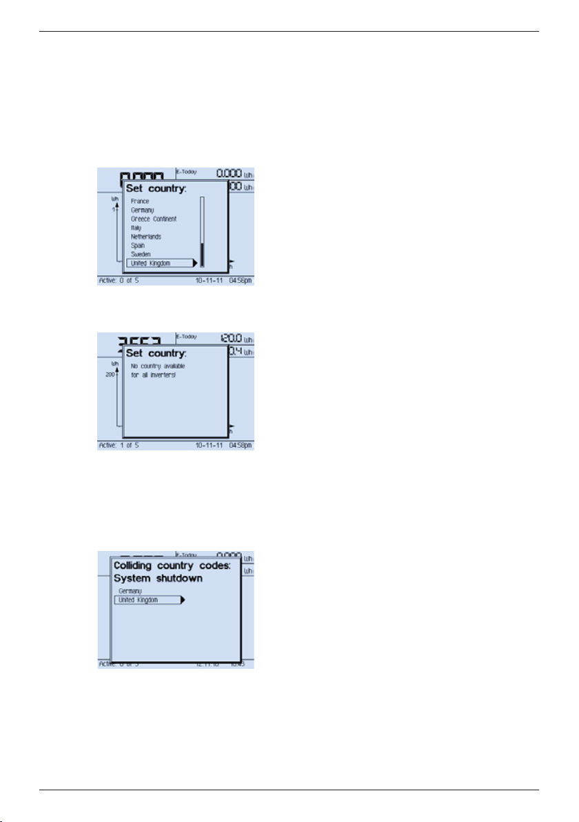
Set country
This message means that the country has not been set
in any of the inverters and these are all running with
their default values. This is typically the case during
initial commissioning.
The displayed country selection list in English shows all
countries whose settings are supported by all inverters.
Select the correct country where your system is
installed.
Set country: No country available for all inverters
This message means that at least two inverters do not
support the same country and cannot feed into the
mains grid for legal reasons. Example:
• Inverter 1 supports Germany, Spain and Portugal.
• Inverter 2 supports France, Italy and Austria.
This message remains displayed until the incompatible
inverter is replaced.
734.144 | Z04 | 2012-11-22
Contact your installer.
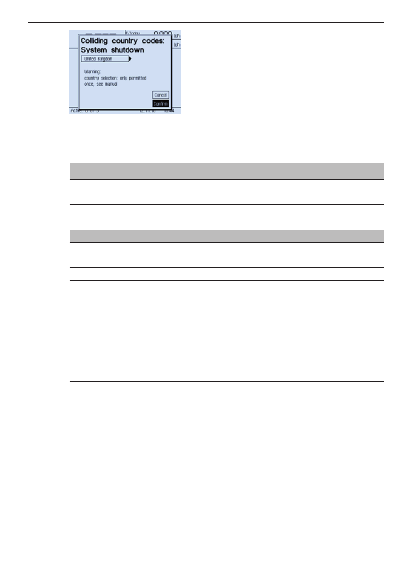
Colliding country codes: System shutdown
This message means that at least two inverters are
set to different countries and cannot feed the mains
grid for legal reasons. This is typically the case when a
system contains inverters that were previously used in
other countries.
The country selection displays the set countries in
English: Example:
• Inverter 1 is set to France.
• Inverter 2 is set to Germany.
If a third inverter with Spain set as the country is also
present then Spain will also be displayed.
53
Page 27
12 Technical data
Application conditions
Area of application Indoors with or without air-conditioning
Ambient temperature –20 °C ... +45 °C
Humidity 0 % ... 95 %
Noise emission Silent
Equipment and design
Degree of protection IP 20
Dimensions (X x Y x Z) 240 x 180 x 63.8 mm
Weight 450 g
Power supply
Supply (output)
Power consumption P
Data interface RS485buswithcablelength≤200m(fromremote
Service interface USB
Test certificate CE mark
Tab. 6: Technical data
Input
Output
1. Use UP / DOWN to select a country.
Note: If your country is not displayed then select
a country with values as close as possible to your
country; see the inverter manual.
2. Press SET. The confirmation message is displayed
(Fig. left).
3. Select Confirm.
4. Press SET. The System daily yield screen is displayed.
Mains adapter plug (included in delivery)
230 V
12 V DC ± 20 %, 1 A, P
1.8 m
≤4W
max
≤4W
max
display or data logger to last inverter)
EN
54
734.144 | Z04 | 2012-11-22
Page 28

EN
13 Legal guarantee
Guarantee conditions for products from Steca Elektronik GmbH
13.1 Defects in materials and workmanship
The guarantee only applies to defects in materials and workmanship, insofar as these
can be attributed to inadequate professional ability on the part of Steca.
Steca reserves the right at its own discretion to repair, adapt or replace the faulty products.
13.2 General information
In accordance with statutory regulations, there is a 2-year legal guarantee on all products for the customer.
For this product, Steca provides a 5-year commercial guarantee from the date of invoice
or receipt. The commercial guarantee applies to products purchased and operated in EU
countries or Switzerland. The commercial guarantee is also available in some countries
outside the EU. Ask Steca about the commercial guarantee available in your country.
The legal guarantee entitlements are not restricted by the voluntary guarantee.
To be able to make a claim under the guarantee the customer must provide proof of
purchase (payment receipt).
If a problem arises, the customer must contact his or her installer or Steca Elektronik
GmbH.
13.3 Guarantee exclusion clause
The guarantees on products from Steca Elektronik GmbH described under point 1 are
not valid in the event that the fault is attributable to: (1) specifications, designs, accessories, or components added to the product by the customer or at the wish of the customer, or special instructions from the customer relating to the production of the product,
the connection (of parts) of Steca products with other products that are not explicitly
approved by Steca Elektronik GmbH; (2) modifications or adjustments to the product by
the customer, or other causes due to the customer; (3) incorrect arrangement or installation, incorrect or careless handling, accident, transport, overvoltage, storage or damage
caused by the customer or other third party; (4) unavoidable accident, fire, explosion,
construction or new construction of any kind in the environment where the product is
located, due to natural phenomena such as earthquakes, flooding, or storms, or any
other cause outside the control of Steca Elektronik GmbH; (5) any other cause that could
not be foreseen or avoided with the technology used in manufacturing the product; (6)
if the serial number and/or the type number has been manipulated or rendered unreadable; (7) the use of the solar products in a movable object, for example ships, mobile
homes, or others.
The guarantee stated in this operating manual only applies to consumers who are customers of Steca Elektronik GmbH or of resellers authorised by Steca Elektronik GmbH.
The guarantee mentioned here is not transferable to a third party. The customer shall
not transfer his rights or responsibilities resulting from this in any way, without the prior
written approval of Steca Elektronik GmbH. Furthermore, Steca Elektronik GmbH shall
in no case be liable for indirect damage or loss of profit. Unless otherwise specified by
any applicable compulsory legislative regulations, Steca Elektronik GmbH shall also not
be liable for any other damages other than those for which Steca Elektronik GmbH has
hereby explicitly accepted liability.
734.144 | Z04 | 2012-11-22
55
Page 29

14 Exclusion of liability
The manufacturer can neither monitor compliance with this manual nor the conditions
and methods during the installation, operation, usage and maintenance of the inverter.
Improper installation of the system may result in damage to property and, as a result, to
bodily injury.
Therefore, Steca Elektronik GmbH assumes no responsibility and liability for loss, damage or costs which result or are in any way related to incorrect installation, improper
operation and incorrect use and maintenance.
Similarly, we assume no responsibility for patent right or other right infringements of
third parties caused by usage of this inverter.
The manufacturer reserves the right to make changes to the product, technical data or
installation and operating instructions without prior notice.
15 Contact
In the case of complaints or faults, please contact the local dealer from whom you purchased the product. They will help you with any issues you may have.
Europe
Steca Elektronik GmbH
Mammostrasse 1
87700 Memmingen
Germany
Phone +49 700 STECAGRID
+49 (0) 700 783 224 743
Monday to Friday from 08:00 a.m. to 4:00 p.m.
Fax +49 (0) 8331 8558 132
Email [email protected]
Internet www.stecasolar.com
EN
16 Notes
..........................................................................................................................................
..........................................................................................................................................
..........................................................................................................................................
..........................................................................................................................................
..........................................................................................................................................
..........................................................................................................................................
56
734.144 | Z04 | 2012-11-22
Page 30
Appendix
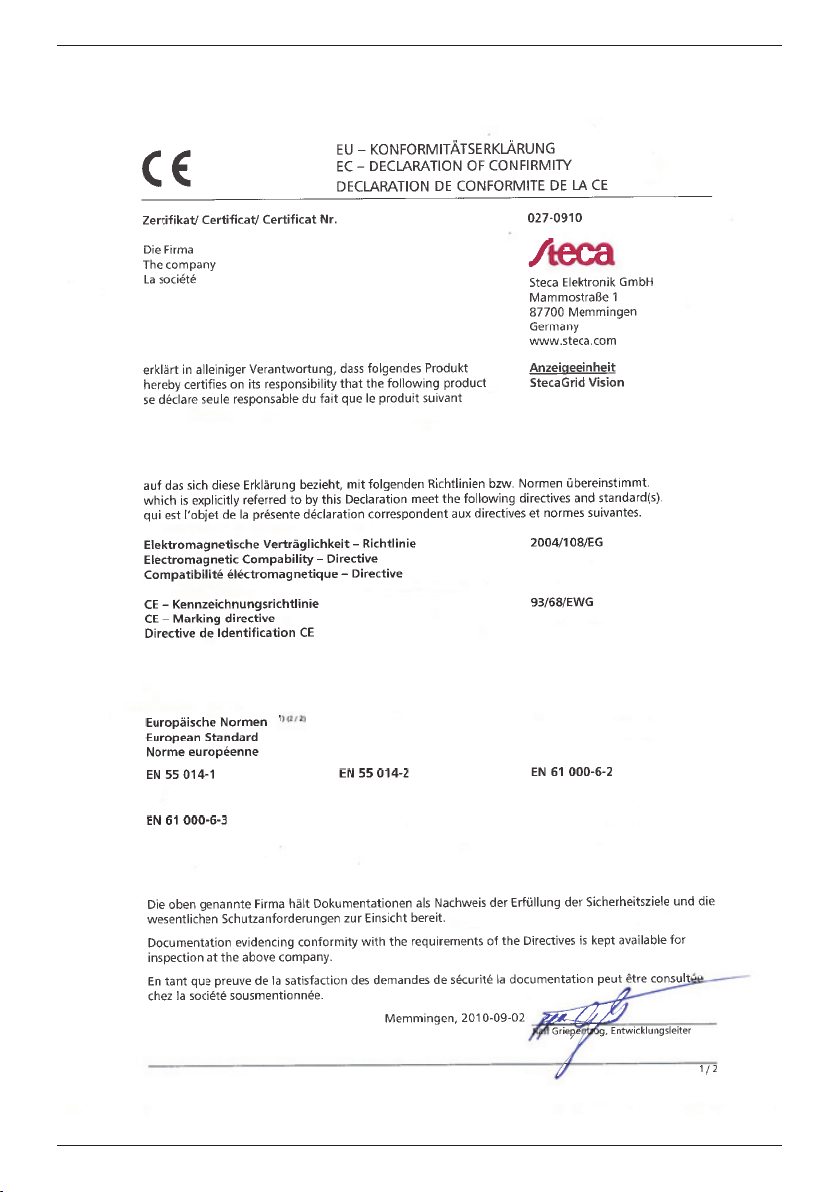
Zertifikate • Certificates • Certificats • Certificati
734.144 | Z04 | 2012-11-22
115
Page 31
Appendix
116
734.144 | Z04 | 2012-11-22
Page 32

Appendix
734.144 | Z04 | 2012-11-22
117
Page 33
Appendix
734144
118
734.144 | Z04 | 2012-11-22
 Loading...