

Steca coolcept fleX StecaGrid 1511, coolcept fleX StecaGrid 3611, coolcept fleX StecaGrid 2011, coolcept fleX StecaGrid 2511, coolcept fleX StecaGrid 3011 Technical Information
...Page 1
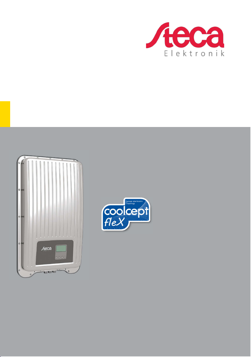
coolcept fleX
Technical Information
EN
Z02 | 1913 | 763.134
Page 2

EN
Preface
Thank you for choosing inverters of the coolcept fleX product family of Steca Elektronik
GmbH. Through the use of solar energy, you significantly help to protect the environment
by reducing the pollution of the atmosphere by the emissions of carbon dioxide (CO
other harmful gases.
Manufacturer: Steca Elektronik GmbH
Mammostrasse 1
87700 Memmingen, Germany
www.steca.com
Phone: 49 (0) 8331 85 58-0
Fax: 49 (0) 8331 85 58-131
Edition: Z02 | March 2019
) and
2
2 763.134 Z02 1913 coolcept_fleX
Page 3

EN
Table of contents
1 General information ................................................................... 6
1.1 Types .................................................................................................................... 6
1.2 Accessories .......................................................................................................... 6
1.3 Documents ........................................................................................................... 6
1.4 Monitoring portal ................................................................................................... 6
1.5 Scope of delivery .................................................................................................. 7
1.6 Labelling ............................................................................................................... 7
1.7 Type plate ............................................................................................................. 7
1.8 EU Declaration of Conformity ............................................................................... 8
1.9 Abbreviations ........................................................................................................ 8
2 Safety .......................................................................................... 9
2.1 General safety instructions ................................................................................... 9
2.2 Designated use ................................................................................................... 10
2.3 Target group ....................................................................................................... 10
2.4 Labels and symbols ............................................................................................ 11
2.4.1 Safety marks ....................................................................................................... 11
2.4.2 Keywords ............................................................................................................ 11
2.5 Safety symbols on the device ............................................................................. 12
3 Structure and functioning ........................................................ 12
3.1 Structure of the inverter ...................................................................................... 12
3.2 Connections ........................................................................................................ 13
3.3 Operating buttons ............................................................................................... 13
3.3.1 Functions of the operating buttons...................................................................... 13
3.4 Display ................................................................................................................ 14
3.5 Cooling ............................................................................................................... 15
3.6 Grid monitoring ................................................................................................... 15
3.7 Data .................................................................................................................... 15
3.7.1 Data communication ........................................................................................... 15
3.7.2 Data display ........................................................................................................ 16
3.7.3 Data storage ....................................................................................................... 16
3.8 Network (TCP/IP)................................................................................................ 16
3.9 "COM1" and "COM2" connections ...................................................................... 17
3.9.1 Connecting further master devices ..................................................................... 17
3.9.2 Connecting further inverters ............................................................................... 18
3.9.3 Fehler! Textmarke nicht definiert.
3.9.4 Alternative RS485 data connecting cable ........................................................... 19
3.9.5 RS485 termination .............................................................................................. 20
3.9.6 RS485 addressing .............................................................................................. 20
3.9.7 Connecting an energy meter (Modbus RTU) ...................................................... 20
3.9.8 Remote shutdown by the grid operator and rapid shutdown
"Teledistacco" (Italy) ........................................................................................... 21
763.134 Z02 1913 coolcept_fleX 3
Page 4

EN
4 Installing the inverter ............................................................... 22
4.1 Safety instructions for installation ....................................................................... 22
4.2 Mounting the inverter .......................................................................................... 23
4.2.1 Attaching the mounting plate .............................................................................. 23
4.2.2 Fixing the inverter to the mounting plate ............................................................. 24
4.3 Preparing AC connection .................................................................................... 24
4.3.1 Selecting AC cable ............................................................................................. 24
4.3.2 Residual current circuit breaker .......................................................................... 25
4.3.3 Assembling the AC plug ..................................................................................... 25
4.4 Preparing DC connection .................................................................................... 28
4.4.1 Fitting cable to DC plug ...................................................................................... 28
4.4.2 Preparing data connecting cable ........................................................................ 28
4.5 Connecting inverter and switching AC on ........................................................... 29
4.6 Performing initial commissioning ........................................................................ 29
4.7 Setting the feed-in management ......................................................................... 30
4.7.1 Switching the energy meter on or off .................................................................. 30
4.7.2 Limiting the dynamic feed-in value...................................................................... 30
4.7.3 Selecting an energy meter .................................................................................. 30
4.8 Switching DC on ................................................................................................. 31
5 Initial commissioning ............................................................... 31
5.1 Setting the display language ............................................................................... 31
5.2 Setting the date and time .................................................................................... 32
5.3 Setting the country .............................................................................................. 32
5.4 Setting the reactive power .................................................................................. 33
5.4.1 Setting the mode................................................................................................. 33
5.4.2 Changing parameters of the nodes..................................................................... 34
5.4.3 Displaying the reactive power characteristic curve ............................................. 34
5.5 Finishing the initial commissioning...................................................................... 34
6 Dismounting the inverter ......................................................... 35
6.1 Switching AC and DC off .................................................................................... 35
6.2 Disconnecting DC connection from inverter ........................................................ 35
6.3 Disconnecting AC plug from inverter .................................................................. 35
6.4 Opening the AC plug .......................................................................................... 36
6.5 Removing inverter from mounting plate .............................................................. 36
7 Operation .................................................................................. 37
7.1 Menu structure .................................................................................................... 37
7.2 Navigating the menu structure ............................................................................ 38
7.3 Status displays.................................................................................................... 38
7.3.1 Displaying output power ..................................................................................... 38
7.4 Main menu .......................................................................................................... 39
7.4.1 Displaying yields ................................................................................................. 39
7.4.2 Generator characteristic curve ............................................................................ 39
7.4.3 Event log ............................................................................................................. 39
7.4.4 Information .......................................................................................................... 40
7.4.5 Self-test (only Italy) ............................................................................................. 41
7.4.6 Settings ............................................................................................................... 42
7.4.7 Service ................................................................................................................ 45
4 763.134 Z02 1913 coolcept_fleX
Page 5

EN
8 Web portal ................................................................................ 48
9 Fault elimination ....................................................................... 49
9.1 Event message type ........................................................................................... 49
9.2 Alerting behaviour ............................................................................................... 50
9.3 Operation ............................................................................................................ 50
9.4 Event messages ................................................................................................. 50
10 Maintenance and care .............................................................. 56
10.1 Maintenance ....................................................................................................... 56
10.2 Care .................................................................................................................... 56
10.2.1 Removing dust .................................................................................................... 56
10.2.2 Cleaning ............................................................................................................. 56
11 Disposal .................................................................................... 56
12 Technical data .......................................................................... 57
12.1 StecaGrid 1511, 2011, 2511, 3011 and 3611 ..................................................... 57
12.2 StecaGrid 3011_2, 3611_2 and 4611_2 ............................................................. 60
13 Table of countries .................................................................... 62
14 Liability, warranty ..................................................................... 62
15 Contact ...................................................................................... 63
16 Annex ........................................................................................ 63
16.1 Drilling pattern for wall mounting......................................................................... 63
763.134 Z02 1913 coolcept_fleX 5
Page 6

EN
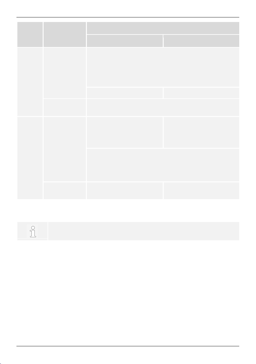
1 General information
These instructions contain information for the safe use of the inverter and all the information that a specialist needs for setting up, and the operator needs for operating the inverter. When installing other components (e.g. PV generator, wiring), follow the instructions
of the respective manufacturer.
The coolcept fleX inverters are available in various models for different power classes.
The StecaGrid #### inverters are suitable for the connection to one PV generator.
The StecaGrid ####_2 inverters are suitable for the connection to two PV generators.
1.1 Types
The coolcept fleX inverters are available in the following models:
• StecaGrid 1511
• StecaGrid 2011
• StecaGrid 2511
• StecaGrid 3011
• StecaGrid 3611
• StecaGrid 3011_2
• StecaGrid 3611_2
• StecaGrid 4611_2
1.2 Accessories
Ask for possible accessories, options, suitable PV generators, and installation material at
the installer's or at Steca.
1.3 Documents
Data sheets, drawings, country tables, and certificates are available in the download area
of the STECA homepage.
1.4 Monitoring portal
Steca's monitoring portal sunCloud offers online monitoring of the PV generator at no
charge: https://steca.powerdoo.com
6 763.134 Z02 1913 coolcept_fleX
Page 7
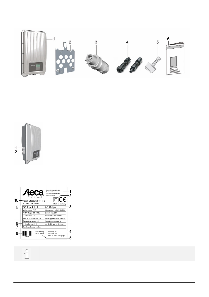
1.5 Scope of delivery
1 Inverter
4 DC plug (one pair*)
1 Type plate
Only for Australia: cover the "Protection Class II" symbol (2) on the type
2 Mounting plate
3 AC plug
* coolcept fleX ####_2: two pairs
1.6 Labelling
5 Sealing cap (3 units)
6 Quick guide
2 Safety marks
EN
1.7 Type plate
1 Manufacturer address
2 "Protection Class II" symbol
3 Technical data of the AC output
4 Standard for grid monitoring
5 Country-specific characteristic
6 Barcode (for internal purposes)
7 Device topology
8 Degree of protection
9 Technical data of the DC input
10 Item number and product name
763.134 Z02 1913 coolcept_fleX 7
plate.
Page 8
EN
Abbreviation
Description
1.8 EU Declaration of Conformity
The products described in this document comply with the applicable European directives.
The certificate is available in the download area of our homepage.
1.9 Abbreviations
AC Alternating Current
DC Direct Current
DHCP
Dynamic Host Configuration Protocol (automatic connection of the
device to an existing network)
DNS Domain Name System (name of the IP address)
LAN Local Area Network
MAC Media Access Control (device address)
MPP Maximum Power Point
MPP tracker Regulates the power of the connected module strings to the MPP
MSD
Mains monitoring with allocated Switching Devices (internal grid
monitoring of the inverter)
PV
Photovoltaics (technology for the conversion of solar energy into
electrical energy)
RTU Remote Terminal Unit
SELV Safety Extra Low Voltage
TCP/IP Transmission Control Protocol/Internet Protocol
URL Uniform Resource Locator (internet address)
8 763.134 Z02 1913 coolcept_fleX
Page 9
2 Safety
The inverter does not cause any inrush current.
NOTE
Any repair work may only be carried out by the manufacturer's customer
service department.
2.1 General safety instructions
• This document must be kept to hand at the site of use of the inverter.
In case of a change of ownership pass on the document with the inverter.
• This document must have been read and understood in full before installing and using
the inverter.
• Incorrectly connected components may cause damage to the inverter.
• If one of the following components is damaged, immediately take the inverter out of
operation and disconnect it from the grid and the PV generators:
- Inverter (not functioning, visible damage, smoke, penetration of liquid etc.)
- Cables
- PV generators
• Do not switch on the system again until it has been repaired and checked by a suitably
qualified and authorised technical specialist.
• Dangerous voltages may be present for up to 10 minutes after disconnecting the inverter from the voltage sources.
• Disconnect inverter from both voltage sources (power grid and PV generator) prior to
any work on the inverter.
• Always carry out the measures described in this document in the specified sequence.
• Do not change nor remove any factory-applied labels on the inverter.
EN
• Do not open the inverter. Danger to life! Opening the inverter will also void any warranty.
• Do not cover the inverter.
• Keep children away from the inverter.
• Follow the instructions of manufacturers of the connected components.
• Follow the general and national safety and accident prevention regulations.
763.134 Z02 1913 coolcept_fleX 9
Page 10
EN
2.2 Designated use
The coolcept fleX inverters are intended for single-phase feed-in and are suitable for indoor
and outdoor (degree of soiling 3) installation. The inverters are designed for wall mounting.
• Only use the inverter for grid-connected PV generators.
• The inverter is suitable for PV generators whose connections are not grounded.
• All connected solar modules must be classified as Class A according to IEC 61730,
because these inverters do not have galvanic isolation.
• The maximum permissible system voltage of the PV generator must be higher than the
AC grid voltage.
• The installation location for the inverter must not be at an altitude higher than 2000 m
above MSL.
NOTE
Only for Australia: the inverter may only be operated as a single device. It is
not permitted to interconnect several devices.
NOTE
Only for Italy: information about the particularities for the use in Italy have
been added to the Italian version of the installation and operating instructions.
2.3 Target group
Unless otherwise noted, the target group for these instructions are specialists and system
operators. The following persons are considered specialists:
• Persons that have knowledge of the established terms and skills for setting up and
operating PV generators.
• Persons that due to their knowledge and experience are able to evaluate the following
tasks and recognise possible hazards:
- Mounting electrical equipment
- Assembling and connecting data cables
- Assembling and connecting power supply cables
10 763.134 Z02 1913 coolcept_fleX
Page 11
2.4 Labels and symbols
2.4.1 Safety marks
The following safety marks are used on the inverter and in these instructions:
Warning sign Nature of the danger
Warning of hazardous voltage
Warning of hazardous area
Follow the instructions
2.4.2 Keywords
The following keywords are used in these instructions:
Keywo rd Meaning
EN
DANGER
Indicates a hazardous situation which, if not avoided, leads to death or
serious injuries.
WARNING
Indicates a potentially hazardous situation which, if not avoided, may
lead to death or serious injuries.
NOTE
Indicates a potentially hazardous situation which, if not avoided, may
lead to damage to property and/or the environment.
763.134 Z02 1913 coolcept_fleX 11
Page 12
EN
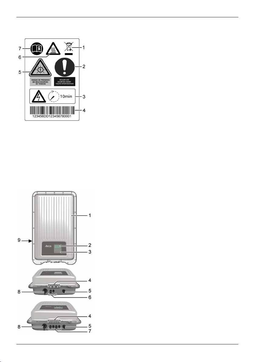
2.5 Safety symbols on the device
1 Disposal information (separate collection of electrical and
electronic equipment)
2 Request to disconnect the power sources prior to any
intervention
3 Information on presence of voltage after switching off the
inverter
4 Serial number (barcode and plain text)
5 Warning of voltage (two voltage sources)
6 Warning of hot surface
7 Follow the instructions
3 Structure and functioning
The coolcept fleX inverter is connected between PV generators and consumers. Via the
DC input and the MPP tracker, PV generators feed in DC, which the inverter converts into
AC. Consumers connected to the AC connection are supplied AC by the inverter.
3.1 Structure of the inverter
1 Case
2 Display (monochrome, 128 x 64 pixels)
3 Operating buttons: ESC, , , SET (from left to right)
4 RJ45 sockets (LAN, COM1, COM2)
5 AC connection
6 DC connection (DC input, MPP tracker)
7 DC connection (StecaGrid ####_2: 2 x DC-input,
2 x MPP tracker)
8 DC disconnector (interrupts the plus and minus inputs
simultaneously)
9 Type plate, serial number, warning notices
12 763.134 Z02 1913 coolcept_fleX
Page 13
3.2 Connections
1 TCP/IP connection (LAN)
4 AC connection
5 DC connection
Button
Acti on
Function
EN
2 RS485 connection (COM1)
3 Modbus RTU connection (COM2)
6 DC connection (StecaGrid ####_2)
7 DC disconnector
3.3 Operating buttons
1 SET
2
3
4 ESC
3.3.1 Functions of the operating buttons
Normal operation Commissioning
ESC Press briefly
Press longer
(≥ 1 second)
Press briefly
- Jumps 1 menu level up
- Discards changes
Jumps to the start image
- Moves the selection bar or the display content upwards
- Moves the selection bar 1 position to the left when setting
numeric values
- Increases the setting value by 1 step
Jumps 1 step back
Jumps to the start of the
guided operation
Press longer
(≥ 1 second)
Browses in menu structure -
Triggers a repetition of the command. The repetition rate
increases when pressing for a longer period
763.134 Z02 1913 coolcept_fleX 13
Page 14
EN
Button
Acti on
Function
Normal operation
Commissioning
At very low temperatures, the display may respond more slowly than usual.
Press briefly
- Moves the selection bar or the display content
downwards
- Moves the selection bar 1 position to the right when
setting numeric values
- Decreases the setting values by 1 step
Browses in menu structure -
Press longer
(≥ 1 second)
SET Press briefly
Triggers a repetition of the command. The repetition rate
increases when pressing for a longer period
- Jumps down by 1 menu
-
level
- Jumps to the diagram
view in certain menus
- A selected value starts flashing and can be changed
- Accepts any entered changes
- Changes the state of a control element (check box / radio
button)
Press longer
(≥ 1 second)
Answers a query dialogue
with Yes
Navigates 1 step forward
3.4 Display
The display shows the menus of the inverter (for an overview of the menus refer to section
7.1).
As a general rule, the menu name is located in the top left corner, and the corresponding
values or selection lines underneath.
14 763.134 Z02 1913 coolcept_fleX
Page 15

EN
The backlight of the display is switched on by pressing any button. The operating states of
the inverter are shown as follows:
Display Meaning
Backlight flashing red
with event message
The inverter is processing large data volumes.
It is not possible to enter user data
Fault
3.5 Cooling
The inverter may heat up during operation. This is a normal operating characteristic.
When the internal temperature rises above a certain value, an internal temperature controller regulates the power consumption from the PV generator. The operating temperature
decreases when power consumption is lower.
A fan disperses the waste heat inside the closed case evenly onto the case surface.
Cooling fins allow the heat to dissipate to the surrounding.
3.6 Grid monitoring
The grid monitoring in the device permanently monitors the grid parameters of the public
grid. If the grid monitoring detects a deviation of the grid parameters from the statutory requirements, the device switches off automatically. When the public grid meets the statutory
requirements again, the device switches on again automatically.
3.7 Data
3.7.1 Data communication
The device has the following communication interfaces:
• "LAN" connection (Ethernet for TCP/IP network) for the communication with a central
data server
• "COM2" connection (Modbus RTU) for the communication with e.g. an external energy
meter
• "COM1" connection (RS485 bus) for the communication with external devices, e.g. with
a data logger (in the case of StecaGrid ####_2: two connections)
For data analysis purposes, the inverter can provide a wide range of data via the RS485
and LAN interfaces (e.g. data logger). The RS485 bus also allows the connection to other
inverters.
763.134 Z02 1913 coolcept_fleX 15
Page 16
EN
3.7.2 Data display
The following data are shown on the display:
• voltage and current generated by the PV generator
• power and current fed into the public grid
• current voltage and frequency of the public grid
• generated energy yields on a daily, monthly and annual basis
• current error states and notes
• Information on the version of the device
3.7.3 Data storage
In the internal memory (EEPROM), event messages and energy yields are stored with the
date. The energy yields are stored for the specified period.
Energy yi eld Storage resolution/period
10-minutes values 31 days
Daily values 13 months
Monthly values 30 years
Annual values 30 years
Total yield Permanent
3.8 Network (TCP/IP)
Via the "LAN" connection, the device can send yield data and event messages to the
server of a web portal. The "Stecagrid Portal" web portal
(https://www.steca.com/index.php?Steca-sunCloud-Registration
resentation of the yield data.
In "Settings" > "Network", the operator can enter the network parameters in further submenu masks (refer to section 7.4.6).
16 763.134 Z02 1913 coolcept_fleX
) allows the graphical rep-
Page 17

EN
Set an external data logger prior to the connection. Follow the instructions of
3.9 "COM1" and "COM2" connections
The inverter can communicate with other device via the "COM1" and "COM2" connections.
Requirements for the communication:
• Both ends of the data connection are terminated.
• RJ45 standard cables or alternative data connecting cables are used as bus cables.
3.9.1 Connecting further master devices
the manufacturers.
Optionally, one of the following master devices can be connected to the "COM1" connection. These devices support the transfer protocol of the inverter.
• StecaGrid SEM, Smart Energy Manager:
- Interface to a ripple control receiver for a feed-in management that is in accordance
with the Renewable Energy Sources Act or EEG (German: Erneuerbare-EnergienGesetz)
• PC or notebook (with related software):
- Read inverter information out with "StecaGrid User Software"
(https://www.steca.com/index.php?StecaGrid-User-en).
- Connection to the inverter possible via optional RS485 adapter => USB; the adapter
is available at Steca, with part number 746.610 (IP21) or 737.707 (IP65).
- Transmission of firmware updates (only specialists).
• External data logger for professional system monitoring (recommended by Steca):
- WEB’log (Meteocontrol)
- Solar-Log (Solare Datensysteme)
- Energy-Manager (Kiwigrid GmbH)
763.134 Z02 1913 coolcept_fleX 17
Page 18

EN
The following inverters have compatible data interfaces and can be con-
1 External data logger
3 Inverter
4 Last inverter, terminated
3.9.2 Connecting further inverters
Inverters connected via the "COM2" connection operate as slave devices. RJ45 standard
cables (patch cables) for outdoor installation are suitable connecting cables.
2 First inverter
nected as slaves to the "COM1" and "COM2" connections:
- StecaGrid 2020
- StecaGrid 1500, 1800, 2000, 2300, 2500, 3010
- StecaGrid 3000, 3600, 4200 and StecaGrid 1500, 1800x
- StecaGrid 2000x, 2300x, 2500x, 3010x, 3000x, 3600x, 4200x
- StecaGrid 1511, 2011, 2511, 3011, 3611, 3011_2, 3611_2, 4611_2
Follow the instructions on addressing, termination, and approved data cables
in the operating instructions of these devices.
5 RJ45 standard cable (patch cable)
18 763.134 Z02 1913 coolcept_fleX
Page 19
EN
Device
Inverter
Solar-Log
WEB’log1)
Kiwigrid
Signal
Connection
COM1/COM2
Terminal block
RJ12
Terminal
3.9.3 Alternative RS485 data connecting cable
NOTE
Voltage may cause property damage.
►
Only have specialists manufacture the alternative data connecting cable.
Use a CAT 5 cable for the alternative data connecting cable in the case of long data connecting distances.
The total length of the data connecting cable shall exceed 1000 m.
If the alternative data connecting cable is connected to the RJ45 socket of the first inverter
and to the connection of the external data logger, the connections in the plug must be assigned in accordance with the following table.
Plug assignment of alternative RS485 data connecting cable
block
1 1 2 A Data A
2 4 4 B Data B
3 - - - -
4 - - - -
Contact
5 - - - -
6 - - - -
7 - - - -
8 3 6 GND Ground
NOTE
1)
Contact 1 of the RJ12 socket supplies 24 V DC!
The RS485 input of the inverter may be damaged.
►
Never connect the alternative data connecting cable to contact 1.
763.134 Z02 1913 coolcept_fleX 19
Page 20
EN
3.9.4 RS485 termination
Terminate the data connection at its beginning and at its end to ensure faultless data transmission:
• Beginning of the data connection: terminate external data logger in accordance with the
manufacturer's instructions.
• End of the data connection: insert termination plug into the vacant RS485 interface of
the last inverter.
3.9.5 RS485 addressing
All inverters are set to address "1" at the factory. For the master-slave communication,
each inverter requires its own address. The address is changed in the menu under "Settings" > "RS485 address".
• If possible, assign the addresses starting with 1 at the first inverter and ascending to the
last, as the number of possible addresses in the inverters is limited.
• The sequence of addresses should mirror the order of the mounted devices, to facilitate
the identification of the devices.
3.9.6 Connecting an energy meter (Modbus RTU)
The inverter is able to communicate with energy meters via the "COM2" connection. To do
this, the energy meter must meet the following requirements:
• The energy meter has been preprogrammed in the inverter.
• The energy meter measures the draw from the grid in positive direction (refer to instruc-
tions of the energy meter).
Modbus RTU data connecting cable
NOTE
Voltage may cause property damage.
►
Only have specialists manufacture the alternative data connecting cable.
Use a RJ45 standard cable or a CAT5 patch cable as data connecting cable.
20 763.134 Z02 1913 coolcept_fleX
Page 21

Plug connection of the Modbus RTU data connecting cable
Connection
COM2
Signal
This configuration meets both the requirements in accordance with VDE-AR-
To allow a rapid shutdown of the generating plant by the grid operator
Device Inverter
RJ45
1 -
2 -
3 -
EN
Contact
4 -
5 -
6 Data A
7 Data B
8 Ground
3.9.7 Remote shutdown by the grid operator and rapid shutdown
"Teledistacco" (Italy)
Assignment of contacts for rapid shutdown
For external fas shutdown, lines 3 and 8 of COM1 or COM2 are connected (e.g. with an
external relay). The following applies:
N-4105 and the requirements for a rapid shutdown ("Teledistacco") for
Italy in accordance with CEI 0-21.
(RAPID SHUTDOWN) via an external device used for control purposes, the
connections "COM1" or "COM2" must be connected as described below.
Assignment of contacts corresponds to the conductor number of the
RJ45 plug.
• Relay closes: Inverters connected to the bus disconnect from the grid.
• Relay opens: Inverters connected to the bus connect to the grid in normal operation.
763.134 Z02 1913 coolcept_fleX 21
Page 22

EN
4 Installing the inverter
4.1 Safety instructions for installation
DANGER
Voltage
Under solar radiation, the PV generators and cables may be energised.
There is the risk of death due electrocution and electric discharge.
►
Disconnect the DC and AC connections from the power source prior to
any work on the inverter:
– Switch off all AC line circuit breakers and secure them against being
switched on again.
– Set the DC disconnector on the inverter to position '0' and secure it
against being switched on again.
– Disconnect the plugs of the DC cables (follow the instructions of the
manufacturer).
– Disconnect AC plug from the inverter: press locking hook on the
AC plug slightly an remove AC plug.
►
Only have specialists carry out any installation work.
►
Only connect the cables to the inverter when it is requested by the instructions.
►
Only connect SELV circuits to the RJ45 socket.
NOTE
Improper installation my cause performance reduction or damages on the inverter.
►
Ensure that the installation site meets the following requirements:
– The mounting surface and immediate surrounding must be: perma-
nently fixed, vertical, level, of low flammability, and not subject to constant vibration.
– The ambient conditions are within the permissible range (refer to chap-
ter 12).
– Open spaces are provided for around the device (above and under-
neath ≥ 200 mm, to the sides and in front ≥ 60 mm).
►
Do not install the device in stables where animals are kept.
►
Avoid exposure to direct sunlight of the device.
►
Ensure that the display can be easily read on the installed device.
22 763.134 Z02 1913 coolcept_fleX
Page 23

EN
Data transmitted via a public network are not protected from being accessed
by third parties.
Data transmission via a public network may cause additional costs.
►
Obtain information on costs possibly involved prior to the use of a public
network.
►
Use a public network at your own risk.
A type A residual current breaker (RCCB) is sufficient.
• Lay the cables such that the connection cannot come loose accidentally.
• Ensure that the fire safety measures of the building are not impaired when routing
cables for the device.
• Make sure that no inflammable gases are present.
• Observe all applicable installation regulations and standards, national laws and connec-
tion values specified by the regional power supply company.
• Observe the connection ratings specified on the type plate.
• Do not connect the DC cables to ground potential.
The DC inputs and the AC output are nor galvanically isolated from each other.
4.2 Mounting the inverter
4.2.1 Attaching the mounting plate
1. Place mounting plate on the mounting surface. The
locking plate (1) must point upwards. The retaining tabs
point to the front.
2. Fasten the mounting plate to the mounting surface with
4 screws. For the drilling pattern refer to chapter 16.
The mounting materials are not included in the scope of
delivery.
763.134 Z02 1913 coolcept_fleX 23
Page 24

EN
Inverter
Cable cross section
Power loss
Circuit breaker
4.2.2 Fixing the inverter to the mounting
plate
1. Place inverter centrally on the mounting plate. In
doing so, hold the inverter by the edge (1).
2. Slightly press on the inverter and slide it downwards.
The locating pins (4) on the inverter must hook into
the retaining tabs on the mounting plate.
3. Introduce detent (2) into the opening of the locking
plate (3). When the detent audibly click into place, the
device can no longer be lifted.
4.3 Preparing AC connection
DANGER
Voltage
There is a risk of death by electrocution.
►
Follow the safety instructions and warning notices in chapter 5.
4.3.1 Selecting AC cable
Install the circuit breaker prior to any work on the AC connection.
Depending on the power of the inverter, you may have to use different circuit breakers and
connecting cables.
AC cable
(with 10 m cable
length)
StecaGrid 1511 1.5 mm² 10 W
4.0 mm² 4W
StecaGrid 2011 1.5 mm² 18 W
4.0 mm² 6 W
StecaGrid 2511 2.5 mm² 16 W
4.0 mm² 11 W
24 763.134 Z02 1913 coolcept_fleX
B16 2.5 mm² 6 W
B16 2.5 mm² 11 W
B16
Page 25

EN
Inverter
Cable cross section
Power loss
Circuit breaker
1 AC plug housing
3 L connection (outer conductor)
AC cable
(with 10 m cable
length)
StecaGrid 3011
and
StecaGrid 3011_2
StecaGrid 3611
and
StecaGrid 3611_2
2.5 mm² 25 W
B16 or B25
4.0 mm² 15 W
2.5 mm² 35 W
B25
4.0 mm² 23 W
StecaGrid 4611_2 2.5 mm² 56 W
B25
4.0 mm² 35 W
4.3.2 Residual current circuit breaker
If the local installation specifications prescribe the installation of an external residual
current circuit breaker, install a residual current circuit breaker. In accordance with
IEC 62109-1, a type A residual current circuit breaker is adequate.
4.3.3 Assembling the AC plug
NOTE
If the instructions of the plug manufacturer are not followed when connecting
the AC plug, the cable and the device may be damaged.
►
Follow the instructions of the plug manufacturer.
Assemble the AC plug (refer to section "Assembly instruction for AC plug") and connect it.
220 V to 240 V grid voltage
Connect conductors N, L, and PE on the AC plug in 1-phase grid with 220 V to 240 V grid
voltage.
2 PE connection
4 N connection (outer conductor)
763.134 Z02 1913 coolcept_fleX 25
Page 26

EN
1 AC plug housing
3 L1 connection (outer conductor)
100 V to 127 V grid voltage
DANGER
Voltage
There is a risk of death by electrocution when connecting the phases L1, L2,
or L3 to PE or N.
►
Follow the safety instructions and warning notices in chapter 5.
The structure of 100 V to 127 V grid voltages differs from that of 220 V to 240 V grid voltages as it is not a 1-phase but a 2 or 3-phase grid.
2 PE connection
4 L2 connection (outer conductor)
Connecting AC plug to 2-phased grid
Connect the inverter between the L1 and L2 outer conductors.
1. Connect the N and L connection of the AC plug (1) between the L1 (3) and L2 (4)
outer conductors of the grid cable.
2. Connect PE cable to PE connection on the AC plug.
Connecting AC plug to 3-phased grid (not depicted)
In the 3-phase grid, there are 3 outer conductors in the cable:
1. Connect N and L connections of the AC plug between any 2 outer conductors
(between L1 and L2, or L1 and L3, or L2 and L3).
2. Connect PE cable to PE connection on the AC plug.
26 763.134 Z02 1913 coolcept_fleX
Page 27

Voltage distribution in the 2 and 3-phase grid
The voltage in 2 and 3-phase grids is the same in every outer conductor: 100 V to 127 V.
Assembly instruction for AC plug
EN
1. Guide cable through the plug housing. Slide plug housing (1) onto the cable.
2. Introduce wire ends (2) into the plug. Ensure that the bending radius of the cables is
large enough (at least 4 times the cable diameter).
3. Using a screwdriver (Pozidriv PZ1) (3), secure wire ends with clamping screws. Tightening torque: 0.8 to 1 Nm. Ensure that the clamping connection holds.
4. Slide plug housing onto the plug and tighten until a click sound is heard.
763.134 Z02 1913 coolcept_fleX 27
Page 28

EN
4.4 Preparing DC connection
DANGER
Voltage
There is a risk of death by electrocution.
►
Follow the safety instructions and warning notices in chapter 5.
►
Use the SUNCLIX plug connectors (DC plugs) included in the scope of delivery to ensure the specified degree of protection.
NOTE
If the DC plugs are not connected correctly to the DC cable, there is a risk of
short circuit. The inverter and modules may be damaged.
►
Connect counterparts to the DC connections to the DC cable ensuring correct polarity.
4.4.1 Fitting cable to DC plug
NOTE
Soiled, displaced, or damaged seals impair the strain relief and the impermeability.
►
Do not soil, shift, nor damage the seals during DC plug assembly.
1. Strip 15 mm of cable end of cable (1).
2. Release spring (2) upwards.
3. Introduce stripped cable end into the
DC plug until the cable end becomes
visible underneath the spring (2).
4. Press spring (2) against the stripped
cable end until it engages audibly. Ensure that the cable end is securely fastened.
5. Slide union nut (4) onto inset (3) of the DC plug.
6. Hold inset with a size 16 wrench and tighten the union nut (4) with a wrench, applying
a tightening torque of 2 Nm.
4.4.2 Preparing data connecting cable
You can use a standard cable (patch cable, CAT4) suitable for outdoor operation or an
alternative RS485 data connecting cable for the data connection. Observe section 3.9.4
when manufacturing an alternative data connecting cable.
28 763.134 Z02 1913 coolcept_fleX
Page 29

4.5 Connecting inverter and switching AC on
DC and AC cables may interfere with data transmission.
DANGER
Voltage
There is a risk of death by electrocution.
►
Follow the safety instructions and warning notices in chapter 5.
EN
►
Keep a distance of 200 mm between the data connecting cables
(RS485/Ethernet) and the DC/AC cables.
NOTE
If sealing caps are missing, moisture may get into the inverter.
►
Seal vacant RJ45 sockets with sealing caps.
1. If required, establish the data connection:
- Connect inverters (mater device and further connected inverters) with data connect-
ing cable(s).
- Switch on termination on the last inverter (slide switch).
2. Seal vacant RJ45 sockets with sealing caps.
3. Press DC plug firmly into the DC connection in the inverter until it engages audibly.
4. Insert AC plug into the AC connection in the inverter until it engages audibly.
5. Switch on the AC circuit breaker.
The display shows the start page of initial commissioning.
4.6 Performing initial commissioning
Any further actions required for the installation of the inverter cannot be carried out before
the initial commissioning has been performed. The initial commissioning is comprehensibly
described in chapter 5.
763.134 Z02 1913 coolcept_fleX 29
Page 30

EN
4.7 Setting the feed-in management
Depending on the country, PV generators must be able to reduce the fed-in active power.
The following products are suitable for implementing this legal requirement:
• StecaGrid SEM
• WEB’log from Meteocontrol
• Solar-Log from Solare Datensysteme
• Energy-Manager from Kiwigrid
An energy meter can be connected to the inverter via the Modbus RTU interface (refer to
section 3.9.7).
The feed-in management is set in the "Energy management"
submenu (refer to section 7.1).
• "Mode": switching the energy meter on or off
• "Dyn. feed in control": limiting the value of feed-in
• "Configuration": selecting an energy meter
4.7.1 Switching the energy meter on or off
• "Off": switching the energy meter off
• "Energymeter": switching the energy meter on
4.7.2 Limiting the dynamic feed-in value
1. Limit the power fed into the grid. You can enter values
starting from 0 W and incrementing by 10 W.
4.7.3 Selecting an energy meter
The inverter can only communicate with the energy meters that
have been preprogrammed.
1. Call the "Metertype" menu by pressing "SET".
2. Using " ", select a meter type from the list of preprogrammed energy meters.
3. Exit the menu with "ESC".
30 763.134 Z02 1913 coolcept_fleX
Page 31

EN
Not until all the checkboxes in the checklist have been marked and the
4.8 Switching DC on
Switching on the DC disconnector on the inverter finishes the
installation of the inverter. After approx. 2 minutes, the display
can show the fed-in power (provided that there is solar radiation).
1. Turn DC disconnector on the inverter to position 'I'.
5 Initial commissioning
After installing and switching on the inverter, the dialogue for initial commissioning starts
automatically. During initial commissioning, the user will navigate through the menu structure via the display.
If the initial commissioning is not completed, the dialogue for initial commissioning will start
again after switching on the inverter.
During initial commissioning, you will set the display language, the date, the time, the country, and the reactive power characteristic curve (only when prescribed for the selected
country).
A checklist with all the settings required for the initial commissioning is shown on the display.
The settings in the menus of the initial commissioning are performed via the operating buttons (for a comprehensive description of the function of the operating buttons, refer to section 3.3).
"Finish" menu is closed, will the initial commissioning be concluded.
5.1 Setting the display language
The default display language is English.
1. Select and confirm the desired language.
763.134 Z02 1913 coolcept_fleX 31
Page 32

EN
5.2 Setting the date and time
1. Select and confirm the desired date format.
2. Set and confirm date/time. The inverter will automatically
correct any invalid input.
5.3 Setting the country
With this menu item, you will set the country of use. Depending on the selection, the inverter will load the grid parameters specified for the country (refer to "Table of countries" in
the download area https://www.steca.com/index.php?coolcept-fleX-1-MPPT-en
https://www.steca.com/index.php?coolcept-fleX-2-MPPT-en).
The country can only be set once. In case of an incorrect input or change of country:
1. Please, contact Steca (ask for password).
2. In the "Del. country settin" menu, delete the set country (password-protected setting).
3. Perform the initial commissioning again.
If the respective country is not present in the country selection, select a country with stricter
specifications.
The selection of a country has no impact on the display language.
1. Select and confirm the country.
2. If a correction is required, return to the country selection
mask by pressing "ESC".
3. If the input is correct, confirm the set country (press "SET"
longer).
and
32 763.134 Z02 1913 coolcept_fleX
Page 33

5.4 Setting the reactive power
The "Reactive power" menu only appears when in the selected country a
The data for the reactive power control are not indicated in the consumer
EN
reactive power setting is prescribed.
counting arrow system but in the generator counting arrow system.
In the "Reactive power" menu, you can set the reactive power mode and display the
reactive power characteristic curve.
5.4.1 Setting the mode
1. Select and confirm the "Mode" menu.
2. Select and confirm the desired mode. The "Reactive
power" menu is displayed again.
If another mode than "cosPhi = 1" has been selected, the display in the "Reactive power" menu will additionally show the
"Load Defaults" and "Number of nodes" menu items. In this
case, additionally perform the following actions:
3. Select and confirm the "Load Defaults" menu.
4. Select the desired defaults and confirm with "SET". The
"Reactive power" menu is displayed again.
5. Select and confirm "Number of nodes".
6. Enter and confirm the number of nodes. The characteristic
curve is freely programmable through the nodes.
7. With "ESC" continue to the "Nodes" menu (for > 2 nodes)
or go back to the "Reactive power" menu (for ≤ 2 nodes).
763.134 Z02 1913 coolcept_fleX 33
Page 34

EN
"P (%)" cannot be changed for the first and the last node (000 %, 100 %).
5.4.2 Changing parameters of the nodes
The "Nodes" menu mask only appears when at least 3 nodes
have been entered.
1. Enter and confirm the desired value for "P" and "cos ψ".
2. Return to the "Reactive power" menu with "ESC".
5.4.3 Displaying the reactive power characteristic curve
The characteristic curve previously entered is displayed.
1. Return to the checklist with "ESC".
5.5 Finishing the initial commissioning
1. Select "Finish" from the checklist and confirm.
If the checklist has not been processed completely, the message "Settings are incomplete"
is displayed. In this case:
1. Press "SET". The checklist is displayed again.
2. Process the open items and finish the processing.
When all settings have been processed, a dialogue stating "Are all settings correct?" is displayed. In this case:
1. Check the settings.
2. If any settings have to be corrected, select the corresponding menu in the checklist and correct the settings.
3. If all the settings are correct: press "SET" longer. The inverter is restarted and synchronises itself with the grid.
After finishing the initial commissioning, you can set the feed-in management and switch
DC on (refer to section 4.7).
34 763.134 Z02 1913 coolcept_fleX
Page 35

6 Dismounting the inverter
The safety instruction from chapter 5 apply.
6.1 Switching AC and DC off
1. Turn DC disconnector on the inverter to position "0".
2. Switch the AC circuit breaker off.
6.2 Disconnecting DC connection from
inverter
DANGER
Voltage can be present at the DC-connection for up to 10 minutes after
switching off the DC circuit breaker.
There is a risk of death by electrocution.
►
Wait 10 minutes after switching off the DC disconnector.
EN
DANGER
The PV generator carries voltage when there is solar radiation.
There is a risk of death by electrocution.
►
Only have specialists carry out any work on the DC connection.
1. Disconnect plug of the DC cables as described in the instructions of the DC plug
manufacturer (refer to annex).
6.3 Disconnecting AC plug from inverter
1. Using a suitable tool, press locking hook on the AC plug slightly in and remove the
plug.
2. Ensure that none of the AC plug poles carries voltage with the help of a suitable voltage tester (do no use a phase testing probe).
763.134 Z02 1913 coolcept_fleX 35
Page 36

EN
6.4 Opening the AC plug
1. Open the rear cable gland.
2. Simultaneously press in the locking hooks on the left and on the right of the plug housing with a suitable tool.
3. Remove the upper part of the housing form the contacting part.
6.5 Removing inverter from mounting
plate
1. Press locking plate (3) towards the wall and hold it
there.
2. Push inverter upwards until the detent (2) can no
longer snap in.
3. Release the locking plate.
4. Hold inverter by the edge (1) with both hands and lift it
off upwards. The locating pins (4) must separate from
the retaining tabs of the mounting plate.
5. Remove inverter from mounting plate.
6. Unscrew the fastening screws of the mounting plate.
7. Remove mounting plate.
36 763.134 Z02 1913 coolcept_fleX
Page 37

EN
7 Operation
7.1 Menu structure
The menu structure of the inverter is divided into Status display, the Main menu und
Submenus, which themselves may contain further submenus.
When switching on the inverter, the "Output power" status display is always shown as start
image. From this status display you can go to all other menus.
763.134 Z02 1913 coolcept_fleX 37
Page 38

EN
Due to further technical development, changes of the menu structure are
For reasons of clarity, only the "" and "SET" operating buttons are depicted in the
menu structure. The individual functions of the operating buttons are described in section 3.4.
possible after delivery of this document. The current version of the menu
structure is available in the download area of our homepage.
7.2 Navigating the menu structure
• To go from one "Output power" status display to the other status displays: scroll through
the status displays with the "" operating buttons.
• To go from the "Output power" status display to the main menu: press "SET".
• To go to the other menu items within the main menu: scroll through the menu with the
"" operating buttons.
• To go from a menu item to a submenu: press "SET".
• To go to other menu items within a submenu: scroll through the submenu with the ""
operating buttons.
• To return from any menu to the "Output power" status display: press and hold "ESC" for
1 second.
7.3 Status displays
The status displays show various measured values. "Output power" and "Grid voltage"
have been preset in the factory and are always displayed. Further status displays that shall
be shown can be defined in "Settings" > "Meas. values".
7.3.1 Displaying output power
1 Menu name
2 Measurement with units
3 Time
4 IP address
In the event of too little solar radiation, the display does not show any measured value (e.g.
at night).
All other menus of the status display are similar in structure and are therefore not mentioned separately.
38 763.134 Z02 1913 coolcept_fleX
Page 39

EN
7.4 Main menu
In the menu items of the main menu and the submenus, you can call various data and perform various settings. The most important menu items are described in the following section. The respective figures show examples.
7.4.1 Displaying yields
Structure of the "Yield" menus:
• On the left: definition of the period (daily/monthly/an-
nual/total)
• On the right: individual yields per period
Via "SET" in the subsequent menu, the period of time displayed can be changed.
The periods contain the following number of individual yields:
- Daily yield: the last 31 days
- Monthly yield: the last 13 months
- Annual yield: the last 30 years
If the inverter had not been installed in one of the listed periods, the yield value "0" is displayed.
Yield (diagram representation)
By pressing "SET" in the menus with the daily, monthly and
annual yields, you can go to the respective diagram view.
7.4.2 Generator characteristic curve
The "Gener. ch. Curve" menu displays the PV generator characteristic curve graphically.
1 Y axis: power in kW
2 Vertex = MPP
3 X axis: input voltage in V
7.4.3 Event log
In the "Event log" menu, it is possible to call event messages sorted chronologically. By
pressing "SET", the list of event messages can be displayed. The event messages possible are described in the section 9.4.
763.134 Z02 1913 coolcept_fleX 39
Page 40

EN
7.4.4 Information
The "Information" menu item contains the following submenu items:
• "Contact info": data for establishing contact with Steca
• "System info" with:
- Product name
- Serial number of the inverter
- Software and hardware versions of the inverter
- Inverter address
- Version of the inverter's operating instructions
• "Country setting": set country and country-specific grid parameters; set during initial
commissioning
• "React.pwr.char. curve": diagram of the reactive power characteristic curve; only in cer-
tain countries
• "Network": network parameters, in part configurable in "Settings" > "Network"
- Hostname
- DHCP status: on/off
- Link status: condition of the network connection
- IP address of the inverter
- Subnet mask
- Gateway: IP address of the network gateway
- DNS address: IP address of the DNS server
- MAC: hardware address of the inverter
• "Results of last self-test" (only when Italy is set in the country setting)
• "Discovery Service": Yes = inverter is visible in the network for other participants of the
network. Yes = inverter is not visible in the network for other participants of the network.
40 763.134 Z02 1913 coolcept_fleX
Page 41

7.4.5 Self-test (only Italy)
Message
Cause
Remedy
If the self-test could not be run successfully, the inverter does no longer feed
The results of the self-test stored in the inverter can be shown on the display
During the self-test, the inverter tests its shutdown behaviour
with regard to too high / too low grid voltage and frequency
(7 test sections, approx. 40 minutes).
You will start the self-test by pressing "SET" longer. While the
self-test is running, the measured values are shown on the display.
If the self-test has been successful, you can exit the menu by pressing "SET".
If a measured value lies outside of the required tolerance, the self-test aborts.
The "Self-test failed" message displayed has to be confirmed by pressing "SET". The, the
self-test has to be repeated as soon as possible.
If not all the required conditions for performing the self-test have been met, an error message appears on the display:
EN
MSD not ready
An error was detected
Invalid grid conditions
Not enough sunlight
in.
►
Repeat self-test as soon as possible.
in "Information" > "Self-test".
The self-test does not start
because the inverter is not
operational
The self-test does not start
because an internal error is
present
Self-test abort due to
invalid network conditions,
e.g. in the event of an AC
voltage that is too low
Self-test does not start or
aborts due to the fact that
the solar radiation is too
low, e.g. in the evening or
at night
Repeat the self-test later,
when the inverter is feeding
in
If this error occurs
repeatedly, inform the
installer
Repeat the self-test later
Repeat the self-test when
there is sufficient solar
radiation
763.134 Z02 1913 coolcept_fleX 41
Page 42

EN
7.4.6 Settings
From the "Settings" main menu you can go to the submenus with configurable parameters
by pressing "SET".
Self-explanatory menus are not described in the following section.
Input mode
The "Input mode" menu is only visible in StecaGrid ####_2 devices with two PV inputs. It is
possible to select the functioning mode of the connected PV inputs: "Independent" or "Parallel".
"Independent"
Both PV inputs (MPP tracker) operate independently from each other.
This mode is applied when connecting two PV generator fields that are differently oriented
to each other, e.g. east/west roof mounting.
"Parallel"
Both PV inputs (MPP tracker) operate synchronously. In this, the MPP tracking is determined by the first PV input.
This mode is applied when mounting two PV generator fields next to each other, e.g. when
the input current exceeds the maximum permissible value in accordance with the type
plate. The PV cables must be connected via a wye junction.
Energy management
The settings related to the energy management are described in "Feed-in management"
(refer to section 4.7). The energy management includes the following submenus:
• "Mode": energy meter can be switched on or off
• "Dyn. feedin control": parameters for feed-in can be set.
• "Configuration": energy meters can be defined more precisely with the "Meter type" and
"Meter position" submenus
Measured values
In the "Meas. values" submenu, you determine which menus
the status display shall contain.
The following measured values are available:
1)
• "Output power": output power of the inverter
• "Current day yield": day yield since 00:00
• "PV voltage": voltage supplied by the PV generators
• "PV current": current supplied by the PV generators
• "PV performance": power generated by the PV generators
42 763.134 Z02 1913 coolcept_fleX
Page 43

• "Grid voltage": voltage at the inverter connection1)
To set up the TCP/IP network connection, an input of parameters is required.
it is not possible to set up the TCP/IP network
• "Grid frequency": frequency of the public grid
• "Internal temp": internal temperature of the inverter
• "Derating": reason for the power reduction
Possible reasons:
- Internal temperature too high
- User default for power limit
- Frequency too high
- Control by grid operator (feed-in management)
- Delayed power increase after start
• "Max. daily power": maximum power of the current day
2)
• "Abs. max. power": highest power fed in2)
• "Day max. yield": max. achieved day yield
2)
• "Operating hours": operating hours on the grid (including hours at night)
• "Total yield ": yield since commissioning
EN
• "CO
1)
2)
saving": CO2 saving since commissioning
2
Measured value is always displayed (it is not possible to switch it off)
Can be reset to zero via "Settings" > "Reset max. vals.".
RS485 address
The address of the RS485 connection can be entered.
Network
By pressing "SET", you can go to the following submenus: "DHCP", "IP address", "Subnet
mask", "Gateway", "DNS", and "Web portal", which itself has submenus.
Without knowing the parameter
connection.
►
If necessary, seek the advice of another specialist.
DHCP is activated in the inverter ex factory. Therefore, the IP address is automatically assigned to the network.
763.134 Z02 1913 coolcept_fleX 43
Page 44

EN
The parameters that are required for network communication
(e.g. with a web portal) are configurable.
The following parameters can be opened and edited by pressing "SET":
• "DHCP"
• "IP address": IP address of the inverter
• "Subnet mask": information on the network and address space
• "Gateway": IP address of the network gateway
• "DNS address": IP address of the DNS server
• "Web portal": parameters related to the web portal
with the following submenus:
- "Setup": selection of the web portal
- "Retransmission": renewed transmission of existing data
- "Connection test": test of the internet connection
Alarm
Acoustic signals for event messages can be switched on or off (factory setting = switched
off):
• 2 sounds: warnings
• 3 sounds: errors
Backlight
The behaviour of the display lighting can be set:
• "Off": no backlight
• "Automatic": the backlight is switched on for 30 seconds after pressing a button
• "Feed-in mode": backlight depends on feed-in
- "No feed-in": switched on for 30 seconds after pressing a button and, then, switched
off
- "Feed-in": switched on for 30 seconds after pressing a button and, then, dimmed
44 763.134 Z02 1913 coolcept_fleX
Page 45

7.4.7 Service
Legally required parameters can be changed in the service menus. Any
EN
change may have a negative effect on the performance of the inverter and
possibly even break a law.
►
Only specialists that can ensure that the changes do not violate any applicable regulations and standards are allowed to perform any changes on
the parameters of the service menus.
To go to the service submenus, the "" operating buttons
must be pressed simultaneously for 3 seconds.
Some dialogues of the service menus are password-protected.
This password can be obtained from Steca's support department (refer to chapter 15).
Setting the reactive power characteristic curve
Setting the reactive power characteristic curve is only required if this is specified for the
selected country.
Deleting the country setting
The selected country setting can be deleted. This task is password-protected (contact to
Steca is required). The inverter restarts and displays the guided initial commissioning
again.
Voltage limits
The voltage limits (peak values of the voltage) can be set by defining the following values:
• "Lower value"
• "Upper value"
763.134 Z02 1913 coolcept_fleX 45
Page 46

EN
Frequency limits
1)
The frequency limits
can be set by defining the following val-
ues:
• "Lower value"
• "Reactivation value"
• "Start value"
• "Upper value"
1)
Switch-on threshold for power reduction (when frequency is too high)
P(f) activation delay
The function of active power limitation for frequency transient
has an activation delay which can be changed.
Voltage limits ø
Voltage limits ø (mean values of the voltage) can be set by defining the following values:
• "Upper value"
• "Lower value"
Power limiter
The output power of the inverter can be limited up to a minimum
of 500 W.
When the power is manually limited, the status display shows
the "Power reduction" symbol and "Reason: user default".
46 763.134 Z02 1913 coolcept_fleX
Page 47

EN
Fixed voltage
Using the inverter for fixed voltage operation is not considered an intended use. If, nevertheless, the inverter shall be used for fixed voltage operation, consultation with Steca is required.
NOTE
The PV generator must be suitable for feeding in a fixed voltage.
Fixed input voltages in the inverter may damage unsuitable PV generators or
reduce their yield.
►
The parameter for fixed voltage are password-protected. The specialist
can only change these parameters after consultation with Steca.
The device can adjust the input voltage to a manually configurable value. Thereby, the automatic setting of the MPP (MPP
tracking) is switched off.
The entered parameter value may lie between the maximum
and minimum input voltage in 1 V increments.
A possible example for application of fixed voltage operation
are hydropower plants.
PowerPeak Scan
With the PowerPeak scan, the energy yield of the inverter can
be improved in the case of partial shadowing of PV strings (e.g.
by parts of buildings, trees or power lines). The current MPP is
intentionally left for a short time to hereby find the better MPP.
The scan is only performed approx. every 10 minutes to impair
the total energy yield caused by the brief power reduction during the scan process as little as possible.
The PowerPeak scan can be switched off in "Settings" >
"Service" > "PowerPeak Scan".
763.134 Z02 1913 coolcept_fleX 47
Page 48

EN
Automatic start of the transmission of unencrypted data.
Factory setting
Resetting the data to factory settings deletes the following data:
• Yield data
• Event messages
• Date and time
• Country setting
• Display language
• Network settings
The inverter restarts. The initial commissioning must be performed again.
All parameters
This menu item allows the change of further ENS parameters (only service technician).
8 Web portal
After establishing the network connection, the inverter automatically starts
data transmission to the server. If automatic transmission is not wanted:
►
Remove network cable.
Or:
►
Deactivate data transmission in "Settings" > "Network".
With the monitoring portal sunCloud, permanently free of charge, online monitoring of
PV generators is easy and comfortable. Registration of the operator and the system in the
sunCloud portal is possible at: https://steca.powerdoo.com
Operator guidance in the sunCloud portal is easy and allows intuitive navigation. After registering and connecting the TCP/IP interface LAN to a PC, the portal displays data (e.g.
yield data and performance of the connected PV generator).
The local network settings for the connection to the server have been set on the inverter.
Setting the local network can be done automatically or manually:
.
• Automatic: if the DHCP prescribes the IP address in the network automatically, no settings are required on the inverter.
• Manual: if the IP address in the network is not assigned automatically, the IP address
must be set manually on the inverter in "Settings" > "Network" (refer to section 7.4.4).
The URL of the web portal is saved permanently in the inverter and cannot be changed.
48 763.134 Z02 1913 coolcept_fleX
Page 49

EN
9 Fault elimination
Event messages indicate faults: the display will be flashing red and a text will describe the
fault present.
Typical display of an event message
Event messages contain the following information:
1 Event message type
2 Date/time of the event message
3 Note on the status of the event:
Active = fault is still present
Date/time = fault was eliminated at the indicated time
4 Cause of the fault
5 Consecutive number / total number in the list of events
6 Acknowledged / not acknowledged fault
Events are acknowledged by pressing the "ESC" or "" operating buttons.
9.1 Event message type
Information
The inverter has detected an error which does not impair feed-in. There is no need for the
user to intervene.
Warning
The inverter has detected an error which may cause reduced yields. It is recommended to
eliminate the cause of error.
Error
The inverter has detected a serious error. The inverter does not feed in as long as the error
is present.
Inform the installer.
763.134 Z02 1913 coolcept_fleX 49
Page 50

EN
By acknowledging the event message, the staff confirms that they have no-
9.2 Alerting behaviour
ticed the event message. The fault, however, persists. The cause of the fault
is not eliminated thus.
New event messages appear immediately on the display. An event message disappears
after the operator has acknowledged the event message or eliminated the cause of the
fault.
If event messages, whose cause has been eliminated, have not yet been acknowledged,
the status display will show an not opened message: .
9.3 Operation
In the main menu, select the "Event log" submenu.
• "SET": a list of the event messages appears.
• "": scroll through the list.
• "NEW": select new event messages by pressing "SET" and acknowledge by pressing
"ESC" or "".
9.4 Event messages
The following table contains examples for event messages and their elimination.
Event message Description Type
Data transfer failed
Grid islanding detected
FE not connected
50 763.134 Z02 1913 coolcept_fleX
A setting has failed, e.g. during initial
commissioning, because it has not been
transmitted correctly.
- Perform the setting again.
- If this error persists, inform the installer.
The grid does not carry voltage. The inverter
must not feed into the grid for safety reasons.
The inverter is switched off as long as this
error condition is present. The display remains
dark.
- If the error occurs repeatedly, inform the
installer.
Functional ground is not connected. The
inverter must not feed into the grid for safety
reasons.
- Inform the installer.
Page 51

EN
Event message
Description
Type
Residual current too high
Boost converter
malfunction
Device overheated
Boost converter has wrong
HW version
Boost converter not
connected
The residual current flowing from the positive
or negative input through the PV generators to
ground exceeds the legally permissible value.
The inverter is switched off automatically as
long as this error condition is present.
- Inform the installer.
An internal component of the inverter is
defective. The inverter does not feed into the
grid or feeds into the grid with reduced power.
- Inform the installer.
Despite power reduction, the maximum
permissible temperature has been exceeded.
The inverter does not feed into the grid until
the permissible temperature range has been
reached.
- Check mounting conditions.
- If the error occurs repeatedly, inform the
installer.
The inverter cannot detect an internal
component, or the component does not match
the other components. The inverter does not
feed into the grid.
- Inform the installer.
The connection of the internal components is
disrupted. The inverter does not feed into the
grid.
- Inform the installer.
Boost converter defect
The boost converter is defective; the inverter
does not feed into the grid or feeds into the
grid with reduced power.
- Inform the installer.
Boost converter not
- Inform the installer.
recognised
Intern. info.
- If the error occurs repeatedly, inform the
installer.
Intern. warning
- If the error occurs repeatedly, inform the
installer.
Intern. error
- If the error occurs repeatedly, inform the
installer.
763.134 Z02 1913 coolcept_fleX 51
Page 52

EN
Event message
Description
Type
Isolation error
No branding
No connection to the
energy meter
L and N swapped
CountryCode failed
Country parameters invalid
The insulation resistance between positive or
negative input and ground falls below the
permissible value. The inverter does not feed
into the grid.
- Inform the installer.
The inverter has wrong or inaccurate device
data. The inverter does not feed into the grid.
- Inform the installer.
There is no communication connection or an
incorrect communication connection between
inverter and energy meter.
- Have the installer check the connection.
Outer and neutral conductors are connected
the wrong way. The inverter must not feed into
the grid for safety reasons.
- Inform the installer.
Inconsistency between the selected country
setting and the one stored in the memory.
- Inform the installer.
The inverter cannot feed into the grid because
it does not have valid parameters.
- Inform the installer.
Power reduction due to
temperature
The inverter reduces its output power because
the maximum temperature has been reached.
- Check mounting conditions.
- If the error occurs repeatedly, inform the
installer.
Reading CountryCode
failed
The inverter has not been able to read out the
set country correctly.
- Inform the installer.
Fan faulty
The internal fan of the inverter is defective.
The inverter does possibly feed into the grid
with reduced power.
- Inform the installer.
52 763.134 Z02 1913 coolcept_fleX
Page 53

EN
Event message
Description
Type
Grid frequency too high for
reactivation
Grid frequency too low for
reactiviation
Grid frequency too high
Grid frequency too low
Grid relay defective
The inverter cannot feed in again after switchoff because the grid frequency exceeds the
legally required switch-on value.
- If the error occurs repeatedly, inform the
installer.
The inverter cannot feed in again after switchoff because the grid frequency falls below the
legally required switch-on value.
- If the error occurs repeatedly, inform the
installer.
The grid frequency present at the inverter
exceeds the permissible value. The inverter is
switched off automatically due to legal
requirements as long as this error condition is
present.
- If the error occurs repeatedly, inform the
installer.
The grid frequency present at the inverter falls
below the permissible value. The inverter is
switched off automatically as long as this error
condition is present.
- If the error occurs repeatedly, inform the
installer.
The inverter has detected a defective grid
relay and does not feed into the grid.
- Inform the installer.
Grid voltage too low for
reactiviation
The inverter cannot feed in again after switchoff because the grid voltage falls below the
legally required switch-on value.
- If the error occurs repeatedly, inform the
installer.
Grid voltage Ø too high
The output voltage averaged over a legally
stipulated period exceeds the permissible
tolerance range. The inverter is switched off
automatically as long as this error condition is
present.
- If the error occurs repeatedly, inform the
installer.
763.134 Z02 1913 coolcept_fleX 53
Page 54

EN
Event message
Description
Type
Grid voltage Ø too low
Grid voltage too high
Grid voltage too high for
reactiviation
Grid voltage too low
The output voltage averaged over a legally
stipulated period falls below the permissible
tolerance range. The inverter is switched off
automatically as long as this error condition is
present.
- If the error occurs repeatedly, inform the
installer.
The grid voltage present at the inverter
exceeds the permissible value. The inverter is
switched off automatically due to legal
requirements as long as this error condition is
present.
- If the error occurs repeatedly, inform the
installer.
The inverter cannot feed in again after switchoff because the grid voltage exceeds the
legally required switch-on value.
- If the error occurs repeatedly, inform the
installer.
The grid voltage present at the inverter falls
below the permissible value. The inverter is
switched off automatically due to legal
requirements as long as this error condition is
present.
- If the error occurs repeatedly, inform the
installer.
Grid current DC offset too
high
The DC current share fed into the grid by the
inverter exceeds the permissible value. The
inverter is switched off automatically due to
legal requirements as long as this error
condition is present.
- Inform the installer.
PV voltage too high
The input voltage present at the inverter
exceeds the permissible value.
- Switch off the DC disconnector of inverter
and inform the installer.
PV current too high
The input current at the inverter exceeds the
permissible value. The inverter limits the
current to the permissible value.
- If the error occurs repeatedly, inform the
installer.
54 763.134 Z02 1913 coolcept_fleX
Page 55

EN
Event message
Description
Type
RS485-Gateway activated
Self test failed
Software incompatible
Overheating HSS
It is not possible to communicate with the
inverter via the RS485 interface.
- Disconnect inverter from the grid and
restart (AC reset).
- Inform the installer.
An error has occurred during self-test; the selftest has been aborted.
- If the self-test is repeatedly aborted at
different times of the day although the grid
voltage and frequency lie within the limit
values of the country setting, inform the
installer.
After a firmware update the various software
versions in the inverter do no longer match.
- Perform the firmware update again with a
valid update file.
- If the error occurs repeatedly, inform the
installer.
The maximum temperature of the boost
converter has been exceeded. The inverter
does not feed into the grid until the permissible
temperature range has been reached.
- Check mounting conditions.
- If the error occurs repeatedly, inform the
installer.
Time/date lost
The inverter has lost the time because it has
been disconnected from the grid for too long.
Storage of yield data is only possible with the
wrong date.
- Correct the time in "Settings" > "Time/date".
763.134 Z02 1913 coolcept_fleX 55
Page 56

EN
Do not dispose of the inverter with household waste.
10 Maintenance and care
10.1 Maintenance
The inverter does not require any maintenance.
10.2 Care
The care of the inverter is limited to the following measures:
• Removing dust
• Cleaning
10.2.1 Removing dust
Remove dust from the cooling fins in the front and rear of the device by using compressed
air of a maximum of 2 bar.
10.2.2 Cleaning
DANGER
Voltage.
There is a risk of death by electrocution.
►
Only clean device with a slightly moist cloth.
Light soiling:
Clean surface of the inverter with a slightly moist cloth (use clear water).
Heavy soiling:
1. Clean surface of the inverter with a slightly moist cloth. In addition, use a cleaning
agent without solvents or disinfectants, that does not contain any granular or sharpedged substances.
2. Remove any residues of the cleaning agent.
11 Disposal
►
►
Return the inverter to Steca customer service with the note: "For disposal".
►
The device packaging consists of recyclable materials.
56 763.134 Z02 1913 coolcept_fleX
Page 57

12 Technical data
The values in the technical data have been determined at a temperature of 25 °C (77 °F).
12.1 StecaGrid 1511, 2011, 2511, 3011 and 3611
EN
StecaGrid
1511
StecaGrid
2011
StecaGrid
2511
StecaGrid
3011
StecaGrid
3611
Installation altitude Max. 2000 m above sea level
DC input side (PV generator connection)
Max. input voltage 450 V 750 V
MPP voltage range 75 V to 360 V
125 V to
600 V
Operating voltage
range at nominal
120 V to
360 V
160 V to
360 V
200 V to
360 V
230 V to
600 V
power
Number of MPP
1
trackers
Max. input current 13 A
Max. input power with
1540 W 2050 W 2560 W 3070 W 3770 W
max. output active
power
Max. short-circuit
15 A
current
AC output side (grid connection)
Output voltage 185 V to 276 V
150 V to
600 V
280 V to
600 V
Nominal output voltage 230 V
Max. output current 12 A 12 A 14 A 14 A 16 A
Max. active power
1500 W 2000 W 2500 W 3000 W 3680 W
(cosPhi = 1)
Maximum apparent
1500 VA 2000 VA 2500 VA 3000 VA 3680 VA
power
Nominal power 1500 W 2000 W 2500 W 3000 W 3680 W
Nominal frequency 50 Hz and 60 Hz
763.134 Z02 1913 coolcept_fleX 57
Page 58

EN
StecaGrid
StecaGrid
StecaGrid
StecaGrid
StecaGrid
1511
2011
2511
3011
3611
Grid frequency 45 Hz to 65 Hz
Power loss during
< 3 W
nighttime operation
Feed-in phases One-phase
Distortion factor
< 3 %
(cosPhi = 1)
Power factor cosPhi 0.8 capacitive to 0.8 inductive
Highest output fault
0.0 A
current
Highest overcurrent
28 A 40 A
protection
Characterisation of the operating behaviour
Max. efficiency 97.40 % 97.40 % 97.40 % 97.00 % 97.00 %
European efficiency 96.10 % 96.50 % 96.60 % 96.30 % 96.30 %
MPP efficiency > 99.7 % (static), > 99 % (dynamic)
Internal consumption < 20 W
Power derating (power
reduction) at full power
50 °C (T
amb
)
45 °C
(T
amb
)
from
Safety
Isolation principle No galvanic isolation, without transformer
Grid monitoring Yes, integrated
Residual current
monitoring
Yes, integrated (the inverter cannot cause a DC residual
current due to the design)
Protection class Protection class 2 (RCD type A sufficient)
Operating conditions
Area of application Indoors, outdoors (degree of soiling 3)
Climate category i.a.w.
4K4H
IEC 60721-3-4
Ambient temperature -25 °C to +60 °C
58 763.134 Z02 1913 coolcept_fleX
Page 59

EN
StecaGrid
StecaGrid
StecaGrid
StecaGrid
StecaGrid
1511
2011
2511
3011
3611
Storage temperature -30 °C to +80 °C
Relative humidity 0 % to 100 %, non-condensing
Noise emission
31 dB(A)
(typical)
Equipment and design
Degree of protection IP 65
Overvoltage category III (AC), II (DC)
DC connection
Phoenix Contact SUNCLIX (1 pair), mating plugs included in
the scope of delivery
AC connection
Wieland RST25i3 plug, mating plug included in the scope of
delivery
Dimensions 399 x 657 x 222 mm
Weight 11.7 kg 12.4 kg
Communication
interfaces
RS-485 (1 x RJ45 socket: connection to Meteocontrol
WEB’log or Solar-Log™), Ethernet interface (1 x RJ45),
Modbus RTU (1 x RJ45 socket: connection to energy meter)
Integrated DC
Yes, conform to DIN VDE 0100-712
disconnector
Cooling principle
Temperature controlled fan, variable-speed, internal
(dust-protected)
Test certificate
Refer to certificates download at the product page of
homepage
763.134 Z02 1913 coolcept_fleX 59
Page 60

EN
12.2 StecaGrid 3011_2, 3611_2 and 4611_2
StecaGrid
3011_2
StecaGrid
3611_2
StecaGrid
4611_2
Installation altitude Max. 2000 m above sea level
DC input side (PV generator connection)
Max. input voltage 750 V
MPP voltage range
Operating voltage range at nominal
power
125 V to
600 V
230 V to
600 V
150 V to
600 V
280 V to
600 V
150 V to
600 V
360 V to
600 V
Number of MPP trackers 2
Max. input current 2 x 13 A
Max. input power with max. output
3070 W 3770 W 4740 W
active power
Max. short-circuit current 15 A
AC output side (grid connection)
Output voltage 185 V to 276 V
Nominal output voltage 230 V
Max. output current 14 A 16 A 20 A
Max. active power (cosPhi = 1) 3000 W 3680 W 4600 W
Maximum apparent power 3000 VA 3680 VA 4600 VA
Nominal power 3000 W 3680 W 4600 W
Nominal frequency 50 Hz and 60 Hz
Grid frequency 45 Hz to 65 Hz
Power loss during nighttime
< 3 W
operation
Feed-in phases One-phase
Distortion factor (cosPhi = 1) < 3 %
Power factor cosPhi 0.8 capacitive to 0.8 inductive
Highest output fault current 0.0 A
60 763.134 Z02 1913 coolcept_fleX
Page 61

EN
StecaGrid
StecaGrid
StecaGrid
Highest overcurrent protection at
3011_2
40 A 40 A 57 A
3611_2
4611_2
the output
Characterisation of the operating behaviour
Max. efficiency 97.00 % 97.00 % 97.40 %
European efficiency 96.30 % 96.30 % 96.90 %
MPP efficiency > 99.7 % (static), > 99 % (dynamic)
Internal consumption < 20 W
Power derating at full power from 45 °C (T
) 45 °C (T
amb
) 40 °C (T
amb
amb
Safety
Isolation principle No galvanic isolation, without transformer
Grid monitoring Yes, integrated
Residual current monitoring
Yes, integrated (the inverter cannot cause a DC
residual current due to the design)
Protection class Protection class 2 (RCD type A sufficient)
Operating conditions
Area of application Indoors, outdoors (degree of soiling 3)
)
Climate category i.a.w.
4K4H
IEC 60721-3-4
Ambient temperature -25 °C to +60 °C
Storage temperature -30 °C to +80 °C
Relative humidity 0 % to 100 %, non-condensing
Noise emission (typical) 31 dB(A)
Equipment and design
Degree of protection IP 65
Overvoltage category III (AC), II (DC)
DC connection
Phoenix Contact SUNCLIX (2 pair), mating plugs
included in the scope of delivery
763.134 Z02 1913 coolcept_fleX 61
Page 62

EN
StecaGrid
StecaGrid
StecaGrid
AC connection
3011_2
Wieland RST25i3 plug, mating plug included in
3611_2
4611_2
the scope of delivery
Dimensions 399 x 657 x 222 mm
Weight 13 kg 13 kg 13.1 kg
Communication interfaces
RS-485 (1 x RJ45 socket: connection to
Meteocontrol WEB’log or Solar-Log™), Ethernet
interface (1 x RJ45), Modbus RTU (1 x RJ45
socket: connection to energy meter)
Integrated DC disconnector Yes, conform to DIN VDE 0100-712
Cooling principle
Temperature controlled fan, variable-speed,
internal (dust-protected)
Test certificate
Refer to certificates download at the product page
of homepage
13 Table of countries
The country of use is set by the installer during the installation of the device. The countryspecific grid parameters will vary depending on the set country of use.
Due to legal requirements, the country.specific values may change at short notice. Any information on the current grid parameters of the countries of use are available in the download area of the Steca homepage.
14 Liability, warranty
The conditions for the device are available for downloading on the Steca homepage:
http://www.steca.com/pv-grid/warranties
62 763.134 Z02 1913 coolcept_fleX
.
Page 63

EN
15 Contact
In the event of complaints or faults, please contact your local dealer, where you purchased
the product. He will assist you in all respects.
Contact in Europe:
Steca Elektronik GmbH
Mammostrasse 1
87700 Memmingen
Germany
Phone: +49 (0) 8331 8558-833
+49 700 STECAGRID
Fax: +49 (0) 8331 8558-132
Web: www.steca.com
16 Annex
16.1 Drilling pattern for wall mounting
763.134 Z02 1913 coolcept_fleX 63
Page 64

Steca Elektronik GmbH
Mammostraße 1
87700 Memmingen
Germany
T +49-(0)8331-8558-0
F +49-(0)8331-8558-131
www.steca.de 763.134
 Loading...