


D
E
C
R
I
N
C
R
HDG NAV APR REV TRIM ALT GS VS
R
D
Y
C
W
S
F
A
I
L
G
P
S
S
VS x 100
F F X
IFTY IVE

3rd Ed. Sep 30, 06 i
S–TEC
List of Effective Pages
* Asterisk indicates pages changed, added, or deleted by
current revision.
Page No. Issue
* 3-7 Apr 15, 07
3-11 Mar 15, 07
* 4-3 Apr 15, 07
Record of Revisions
Retain this record in front of handbook. Upon receipt of a
revision, insert changes and complete table below.
Revision Number Revision Date Insertion Date/Initials
1st Ed. Nov 08, 00
2nd Ed. May 31, 02
3rd Ed. Sep 30, 06
1st Rev. Mar 15, 07
2nd Rev. Apr 15, 07
2nd Rev. Apr 15, 07

ii 3rd Ed. Sep 30, 06
S–TEC
Page Intentionally Blank

3rd Ed. Sep 30, 06 iii
S–TEC
Table of Contents
Sec. Pg.
1 Overview ...........................................................................................................1–1
1.1 Document Organization....................................................................1–3
1.2 Purpose..............................................................................................1–3
1.3 General Control Theory ....................................................................1–3
1.4 Modes of Operation...........................................................................1–4
1.4.1 Roll Axis Control.................................................................1–4
1.4.2 Pitch Axis Control...............................................................1–4
1.5 Block Diagram....................................................................................1–4
2 Pre-Flight Procedures...................................................................................2–1
2.1 Power-Up T est....................................................................................2–3
2.2 Pre-Flight T est....................................................................................2–6
3 In-Flight Procedures......................................................................................3–1
3.1 Normal Operating Procedures........................................................3–3
3.1.1 Heading (HDG) Mode........................................................3–3
3.1.2 Navigation (NAV) Mode......................................................3–3
3.1.2.1 Pilot Selectable Intercept Angle........................3–6
3.1.3 Navigation GPSS (NAV GPSS) Mode...............................3–7
3.1.3.1 Pilot Selectable Intercept Angle........................3–7
3.1.4 Altitude Hold (ALT HOLD) Mode.......................................3–8
3.1.5 Vertical S peed (VS) Mode.................................................3–8
3.1.6 Control Wheel S teering (CWS) Mode .............................3–9
3.1.7 Elevator Trim.......................................................................3–9
3.1.7.1 Manual Elevator Trim.........................................3–9
3.1.7.2 Automatic Elevator Trim....................................3–10
3.1.7.3 Manual Electric Elevator Trim..........................3–1 1

iv 3rd Ed. Sep 30, 06
S–TEC
3.2 Precision Approach Procedures.....................................................3–12
3.2.1 Straight-In ILS Approach....................................................3–12
3.2.1.1 Software Revision 5 and Above......................3–12
3.2.1.2 Software Revision 4 and Below......................3–14
3.2.2 ILS Approach with Procedure Turn................................3–15
3.3 Non-Precision Approach Procedures............................................3–15
3.3.1 Straight-In Back Course Approach..................................3–15
3.3.1.1 Pilot Selectable Intercept Angle.......................3–17
3.3.2 Back Course Approach with Procedure T urn...............3–18
3.3.3 Straight-In LOC Approach................................................3–21
3.3.4 Straight-In VOR Approach.................................................3–23
3.3.5 LOC Approach with Procedure T urn..............................3–25
3.3.6 VOR Approach with Procedure T urn..............................3–28
3.3.7 NA V GP SS Approach..........................................................3–31
3.4 Flight Director Operation..................................................................3–31
3.4.1 FD/AP Mode.........................................................................3–31
3.4.2 FD Mode...............................................................................3–32
3.5 Y aw Damper Operation....................................................................3–33
3.5.1 AUTO Mode..........................................................................3–34
3.5.2 ON Mode..............................................................................3–34
3.5.3 Yaw Damper Trim..............................................................3–34
3.6 Autopilot Disconnect ........................................................................3–34
3.7 Automatic Trim Disable....................................................................3–34
4 Operating Parameters..................................................................................4–1
4.1 Roll Axis Limits..................................................................................4–3
4.2 Pitch Axis Limits.................................................................................4–3
5 Glossary ...........................................................................................................5–1

3rd Ed. Sep 30, 06 v
S–TEC
List of Figures
Fig. Pg.
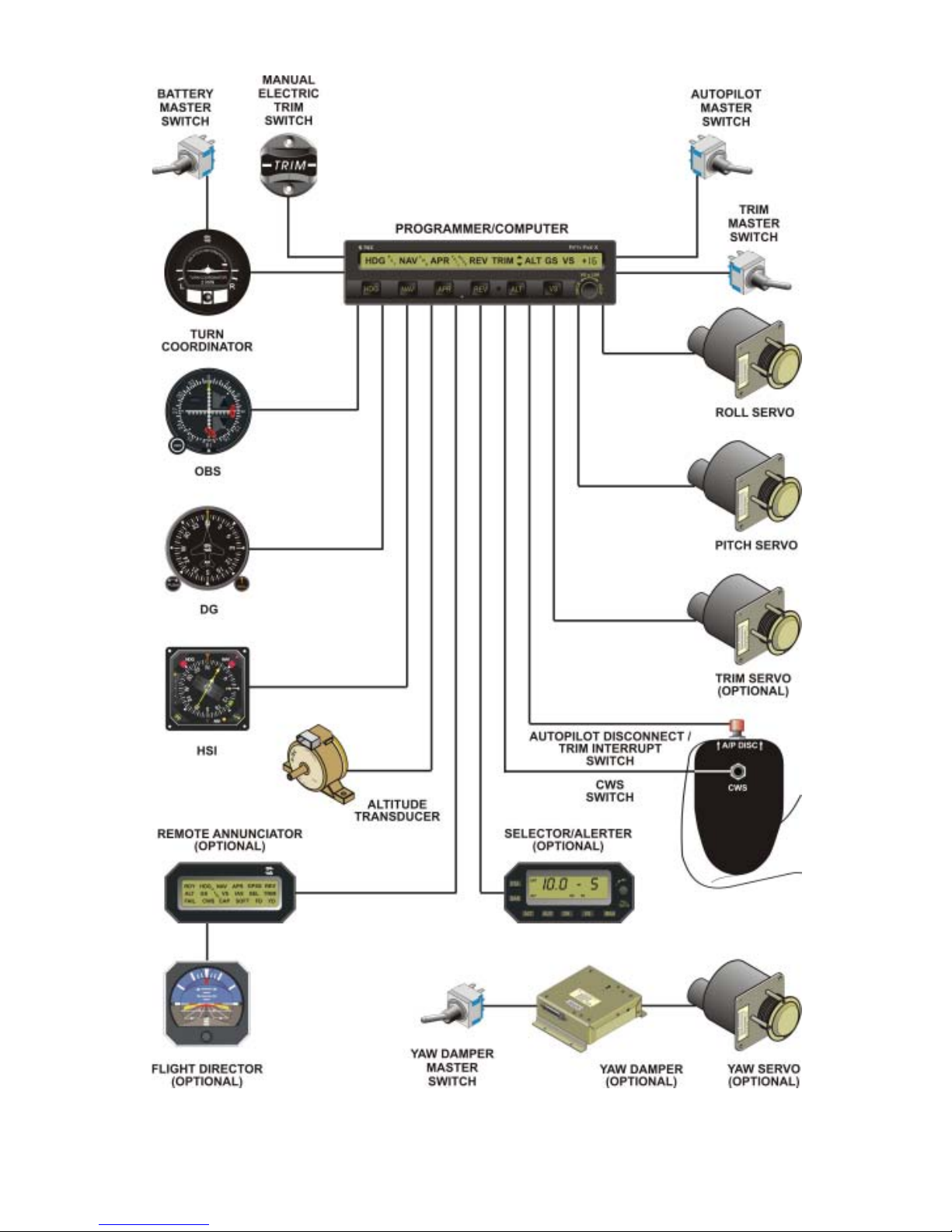
1–1 System Fifty Five X Block Diagram..............................................................1–5
2–1 AP Display , All Annunciations at Power-Up................................................2–4
2–2 AP Display , Software Revision Number .....................................................2–4
2–3 AP Display , Ready for Operation.................................................................2–4
2–4 AP Display , Programmer/Computer Failure.............................................2–5
2–5 AP Display , T urn Coordinator Failure.........................................................2–5
2–6 AP Display , HDG Mode Engaged (Pre-Flight) ..........................................2–7
2–7 AP Display , HDG and AL T HOLD Modes Engaged (Pre-Flight)..............2–7
2–8 AP Display , CWS Mode Armed or Engaged, 0 FPM (Pre-Flight).............2–9
2–9 AP Display, CWS Mode Engaged, 500 FPM Climbing (Pre-Flight)........2–9
2–10 AP Display, CWS Mode Engaged, 500 FPM Descending (Pre-Flight)...2–9
2–11 AP Display , NA V and VS Modes Engaged, 0 FPM (Pre-Flight)...............2–1 1
2–12 AP Di sp la y , Manual T rim Prompts (Pre-Flight).......................................2–13
2–13 AP Display , Automatic Trim Advisement s (Pre-Flight)...........................2–15
2–14
Remote Annunciator Display, HDG , VS, and FD Modes Engaged (Pre-Flight)...2–15
2–15 AP Display , Manual Electric T rim in Progress (Pre-Flight)....................2–18
3–1 AP Display , HDG Mode Engaged................................................................3–3
3–2 AP Display , NA V Mode Engaged..................................................................3–3
3–3 Remote Annunciator Display, NA V Mode Engaged, CAP Condition.......3–5
3–4 Remote Annunciator Display , NA V Mode Engaged, CAP SOFT Condition.......3–5
3–5 Remote Annunciator Display, NAV Mode Engaged, SOFT Condition.....3–5
3–6 AP Display , NA V APR Mode Engaged.........................................................3–6
3–7
Remote Annunciator Display, NAV APR Mode Engaged, CAP SOFT Condition....3–6
3–8 AP Display , HDG Mode Engaged, NA V Mode Armed................................3–6
3–9 AP Display , NA V GPSS Mode Engaged......................................................3–7
3–10 AP Display, HDG Mode Engaged, NA V GPSS Mode Armed.....................3–7

vi 3rd Ed. Sep 30, 06
S–TEC
3–11 AP Display , HDG and AL T HOLD Modes Engaged...................................3–8
3–12 AP Display , HDG and VS Modes Engaged.................................................3–9
3–13 AP Display, CWS Mode Engaged................................................................3–9
3–14 AP Display , Manual Trim Prompts............................................................3–14
3–15 AP Display, Automatic Trim Advisements.................................................3–11
3–16 AP Display, Manual Electric T rim in Progress..........................................3–12
3–17 AP Display, NA V APR and AL T HOLD Modes Engaged...........................3–13
3–18
AP Display , NAV APR and ALT HOLD Modes Engaged, GS Mode Armed...............3–13
3–19 AP Display , NA V APR and GS Modes Engaged.......................................3–13
3–20 Straight-In ILS Approach...............................................................................3–14
3–21
AP Display , REV APR Mode Engaged, Track LOC Back Course Inbound...........3–16
3–22 AP Display, S traight-In Back Course Approach.......................................3–16
3–23 AP Display, HDG Mode Engaged, REV APR Mode Armed.....................3–17
3–24
AP Display , NA V APR Mode Engaged, Track LOC Back Course Outbound......3–18
3–25 AP Display , REV APR Mode Engaged, Track LOC Back Course Inbound...........3–19
3–26 Back Course Approach with Procedure Turn..........................................3–20
3–27
AP Display , NA V APR Mode Engaged, Track LOC Front Course Inbound..........3–21
3–28 Straight-In LOC Approach............................................................................3–22
3–29
AP Display , NA V APR Mode Engaged, Track VOR Front Course Inbound.........3–23
3–30 Straight-In VOR Approach............................................................................3–24
3–31
AP Display , REV APR Mode Engaged, Track LOC Front Course Outbound.......3–25
3–32
AP Display , NA V APR Mode Engaged, Track LOC Front Course Inbound..........3–26
3–33 LOC Approach with Procedure Turn........................................................3–27
3–34
AP Display , REV Mode Engaged, T rack VOR Front Course Outbound............3–28
3–35
AP Display , NA V APR Mode Engaged, Track VOR Front Course Inbound.........3–29
3–36 VO R Approach with Procedure Turn........................................................3–30
3–37 FD Parallax Adjustment................................................................................3–31

3rd Ed. Sep 30, 06 vii
S–TEC
3–38 AP Master Switch, FD/AP Mode Engaged................................................3–31
3–39 FD Display, FD/AP Mode Engaged...........................................................3–32
3–40 AP Master Switch, FD Mode Engaged......................................................3–32
3–41 Remote Annunciator Display , FD Mode Engaged..................................3–32
3–42 FD Display, FD Mode Engaged.................................................................3–33
3–43 Yaw Damper Master Switch........................................................................3–33
3–44 Yaw Damper Trim Knob..............................................................................3–33
List of Tables
Table Pg.
2–1 Power-Up T est...............................................................................................2–3
2–2 Pre-Flight T est...............................................................................................2–6

viii 3rd Ed. Sep 30, 06
S–TEC
Page Intentionally Blank

3rd Ed. Sep 30, 06 1-1
S–TEC
SECTION 1
OVERVIEW

1-2 3rd Ed. Sep 30, 06
S–TEC
Page Intentionally Blank

3rd Ed. Sep 30, 06 1-3
S–TEC
1.1 Document Organization
Section 1 Overview
Section 2 Pre-Flight Procedures
Section 3 In-Flight Procedures
Section 4 Operating Parameters
Section 5 Glossary
1.2 Purpose
This Pilot's Operating Handbook (POH) provides Pre-Flight and In-Flight
operating procedures for the S-TEC System Fifty Five X Autopilot (AP).
Note:
This POH must be carried in the A/C and made available to the pilot at
all times. It can only be used in conjunction with the Federal Aviation
Administration (FAA) approved Aircraft Flight Manual (AFM) or Aircraft Flight
Manual Supplement (AFMS). Refer to the applicable AFM or AFMS for
A/C specific information, such as unique ground tests, limitations, and
emergency procedures.
Note:
The System Fifty Five X autopilot is a tool provided to aircraft owners, that
serves to assist them with cockpit workload management. The ability of the
autopilot to provide optimum assistance and performance is directly
proportional to the pilot's knowledge of its operating procedures. Therefore,
it is highly recommended that the pilot develop a thorough understanding of
the autopilot, its modes, and operating procedures in Visual Meteorological
Conditions (VMC), prior to using it under Instrument Flight Rules (IFR).
1.3 General Control Theory
The System Fifty Five X is a rate based autopilot. When in control of the roll axis,
the autopilot senses turn rate, as well as closure rate to the selected course,
along with the non-rate quantities of heading error, course error, and course
deviation indication. When in control of the pitch axis, the autopilot senses
vertical speed, acceleration, and closure rate to the selected glideslope, along
with the non-rate quantities of altitude and glideslope deviation indication. These
sensed data provide feedback to the autopilot, which processes them in order to
control the aircraft through the use of mechanisms coupled to the control
system. In most aircraft, the roll servo is coupled to the ailerons. The pitch
servo is coupled to the elevator. Activation of roll axis control must always
precede activation of pitch axis control.
The optional autotrim function senses when the aircraft needs to be trimmed
about the pitch axis, and responds by driving the trim servo in the proper
direction to provide trim. The trim servo is coupled to the elevator trim tabs.
The optional yaw damper senses excessive adverse yaw about the yaw axis,
and responds by driving the yaw servo in the proper direction to provide
damping. The yaw servo is coupled to the rudder.

1-4 3rd Ed. Sep 30, 06
S–TEC
1.4 Modes of Operation
1.4.1 Roll Axis Control
Heading (HDG) Mode
Used to Turn onto a Selected Heading and Hold it
Navigation (NA V) Mode
Used to Intercept and Track a VOR Course
Navigation Approach (NAV APR) Mode
Used to Intercept and Track a LOC and VOR Front Course Inbound
Reverse (REV) Mode
Used to Intercept and Track a VOR Back Course Inbound
Reverse Approach (REV APR) Mode
Used to Intercept and Track a LOC Back Course Inbound
Navigation Global Positioning System Steering (NAV GPSS) Mode
Used to Laterally Steer along a Course defined by GPS
Control Wheel Steering (CWS) Mode
Used to Simultaneously Hold Turn Rate and Vertical Speed
1.4.2 Pitch Axis Control
Altitude Hold (ALT HOLD) Mode
Used to Hold Altitude
Vertical Speed (VS) Mode
Used to Hold Vertical Speed
Glideslope (GS) Mode
Used to Intercept and Track Glideslope
1.5 Block Diagram
The System Fifty Five X Block Diagram is shown in Fig. 1-1.
3rd Ed. Sep 30, 06 1-5
S–TEC
Fig. 1-1. System Fifty Five X Block Diagram

1-6 3rd Ed. Sep 30, 06
S–TEC
Page Intentionally Blank

3rd Ed. Sep 30, 06 2-1
S–TEC
SECTION 2
PRE-FLIGHT PROCEDURES

2-2 3rd Ed. Sep 30, 06
S–TEC
Page Intentionally Blank

3rd Ed. Sep 30, 06 2-3
S–TEC
2.1 Power-Up Test
Perform the actions shown in Table 2-1. For each action, verify the corresponding
response where applicable.
T able 2-1. Power-Up Test
ACTION RESPONSE
1. Set Yaw Damper Master Switch
to OFF position (if installed).
------
2. Set Trim Master Switch to OFF
position (if installed).
------
3. Set Battery Master Switch to ON
position.
------
4. Set Avionics Master Switch to ON
position.
------
5. Set Autopilot Master Switch to one
of the following positions, whichever
is applic abl e:
All annunciations appear on AP
display as shown in Fig. 2-1 for 10
seconds, and then extinguish.
FD/AP (Flight Director Installed)
AP (No Flight Director)
For Programmer/Computers with
serial number greater than 3001,
software revision number briefly
appears on AP display between 10
and 20 seconds following power-up,
as shown in Fig. 2-2.
RDY annunciation alone re-appears
on AP display within 3 minutes, as
shown in Fig. 2-3 (No tes 1, 2 ) .
Notes:
1. Should a Programmer/Computer failure be detected, the FAIL annunciation
alone will re-appear on the AP display as shown in Fig. 2-4, and the autopilot will
not operate.
2. Should a Turn Coordinator failure be detected, the AP display will remain
blank indefinitely as shown in Fig. 2-5, and the autopilot will not operate.

2-4 3rd Ed. Sep 30, 06
S–TEC
Fig. 2-1. AP Display, All Annunciations at Power-Up
Fig. 2-2. AP Display, Software Revision Number
Fig. 2-3. AP Display , Ready for Operation

3rd Ed. Sep 30, 06 2-5
S–TEC
Fig. 2-4. AP Display, Programmer/Computer Failure
Fig. 2-5. AP Display , T urn Coordinator Failure

2-6 3rd Ed. Sep 30, 06
S–TEC
ACTION RESPONSE
1. Move A/C Control Wheel left and
right, to sense its freedom of
movement about roll axis.
------
2. Set Heading Bug under Lubber
Line.
------
3. Press HDG mode selector switch
to engage heading mode.
HDG annunciation alone appears on
AP display, as shown in Fig. 2-6.
4. Attempt movement of A/C Control
W h eel l eft and rig ht .
A/C Control Wheel’s reduced
freedom of movement indicates that
Roll Servo is engaged.
Roll Servo can be overridden. If not,
disconnect autopilot and do not use.
5. Turn Heading Bug to the left side
of Lubber Line.
A/C Co ntrol Wheel tur ns to the left .
6. Turn Heading Bug to the right side
of Lubber Line.
A/C Control Wheel turns to the right.
7. Set Heading Bug under Lubber
Line.
A/C Control Wheel stops.
8. Move A/C Control Wheel forward
and aft, to sense its freedom of
movement about pitch axis.
------
9. Press ALT mode selector switch to
engage altit ude hold mode.
ALT annunciation appears with HDG
on AP display, as shown in Fig. 2-7.
10. Atte mpt movement of A/C
Control Wheel forward and aft.
A/C Control Wheel’s reduced
freedom of movement indicates that
Pitch Servo is engaged.
Pi t ch Servo can be overridden. If not,
disconnect autopilot and do not use.
T able 2-2. Pre-Flight T est (continued on p age 2-8)
2.2 Pre-Flight T est
Prior to takeoff and with engine running, perform the actions shown in Table 2-2.
For each action, verify the corresponding response where applicable. All actions
pertaining to mode selector switches apply to the autopilot bezel.

3rd Ed. Sep 30, 06 2-7
S–TEC
Fig. 2-6. AP Display , HDG Mode Engaged (Pre-Flight)
Fig. 2-7. AP Display , HDG and AL T HOLD Modes Engaged (Pre-Flight)

2-8 3rd Ed. Sep 30, 06
S–TEC
T able 2-2. Pre-Flight Test (continued from page 2-6)
ACTION RESPONSE
11. Press/Hold CWS Switch to arm
control wheel steering mode.
CWS, VS, and +0 (or ±1)
annunciations only appear on AP
display, as s h own in Fi g. 2-8.
12. Move A/C Control Wheel left and
right.
A/C Control Wheel’s increased
freedom of movement indicates that
Roll Servo is disengaged.
13. Move A/C Control Wheel for ward
and aft.
A/C Control Wheel’s increased
freedom of movement indicates that
Pitch Servo is disengaged.
14. Release CWS Switch to engage
control wheel steering mode.
------
15. Atte mpt movement of A/C
Con trol Wheel left and right.
A/C Control Wheel’s reduced
freedom of movement indicates that
Roll Servo is engaged.
16. Atte mpt movement of A/C
Control Wheel forw ard and aft.
A/C Control Wheel’s reduced
freedom of movement indicates that
Pitch Servo is engaged.
17. Rotate AP Modifier Knob CW
until +5 (500 FPM climbing) is
commanded, as shown in Fig. 2-9.
A/C Control Wheel moves in aft
directon.
18. Rotate AP Modifier Knob CCW
until -5 (500 FPM descending) is
commanded, as shown in Fig. 2-10.
A/ C Con trol Wh eel m oves i n fo rwar d
direction.
19. Rotate AP Modifier Knob CW
until +0 (0 F PM) i s comman ded.
A/ C C ontr ol W heel stops.
Note: If it is not possible to select a local VOR frequency on Navigation
Receiver, then proceed to step 30. Otherwi se, proc eed to step 20 .

3rd Ed. Sep 30, 06 2-9
S–TEC
Fig. 2-8. AP Display , CWS Mode Armed or Engaged, 0 FPM (Pre-Flight)
Fig. 2-9. AP Display , CWS Mode Engaged, 500 FPM Climbing (Pre-Flight)
Fig. 2-10. AP Display, CWS Mode Engaged, 500 FPM Descending (Pre-Flight)
 Loading...