

Page 1
®
Spring-Set Disc Brakes
Important
Please read these instructions carefully
before installing, operating, or servicing
your Stearns brake. Failure to comply with
these instructions could cause injury to
personnel and/or damage to property if
the brake is installed or operated
incorrectly. For definition of limited
warranty/liability, contact Rexnord
Industries, Inc., Stearns Division,
5150 S International Drive.,
Cudahy, WI 53110, (414) 272-1100.
Caution
1. Installation and servicing must be made
in compliance with all local safety
codes including Occupational Safety
and Health Act (OSHA). All wiring and
electrical connections must comply with
the National Electric Code (NEC) and
local electric codes in effect.
2. Do not install the brake in atmospheres
containing explosive gases or dusts,
corrosive substances, water, oil or dust.
3. To prevent an electrical hazard,
disconnect power source before
working on the brake. If power
disconnect point is out of sight, lock
disconnect in the
off
position and tag to
prevent accidental application of power.
4. Be careful when touching the exterior
of an operating brake. Allow sufficient
time for brake to cool before
disassembly. Surfaces may be hot
enough to be painful or cause injury.
5. Do not operate brake with housing
removed. All moving parts should be
guarded.
6. After usage, the brake interior will
contain burnt and degraded friction
material dust. This dust must be
removed before servicing or adjusting
the brake.
DO NOT BLOW OFF DUST using an
air hose. It is important to avoid
dispersing dust into the air or inhaling it,
as this may be dangerous to your
health.
a) Wear a filtered mask or a respirator
while removing dust from the inside
of a brake.
b) Use a vacuum cleaner or a soft
brush to remove dust from the brake.
When brushing, avoid causing the
dust to become airborne. Collect the
dust in a container, such as a bag,
which can be sealed off.
7. Installation and servicing should be
performed only by qualified personnel
familiar with the construction and
operation of the brake.
8. For proper performance and operation,
only genuine Stearns parts should be
used for repairs and replacements.
General Description
The 48,100 series is a spring-set,
electrically released disc brake for
controlled stopping and holding of a load.
It has a single-phase solenoid coil for
operation on alternating current only. The
nominal static torque is factory set.
Construction
The 48,100 series brake utilizes one
composition friction disc driven by a metal
hub that is fastened to the motor shaft.
Manual release with automatic electrical
reset is provided. Splined hub and friction
disc is standard. Only open enclosure is
available.
Operation
When brake is properly wired, starting the
motor will energize the solenoid and
compress the pressure spring. This action
removes the force against the stationary
plate and friction disc and allows the disc
to rotate freely. Stopping the motor will deenergize the solenoid and restores
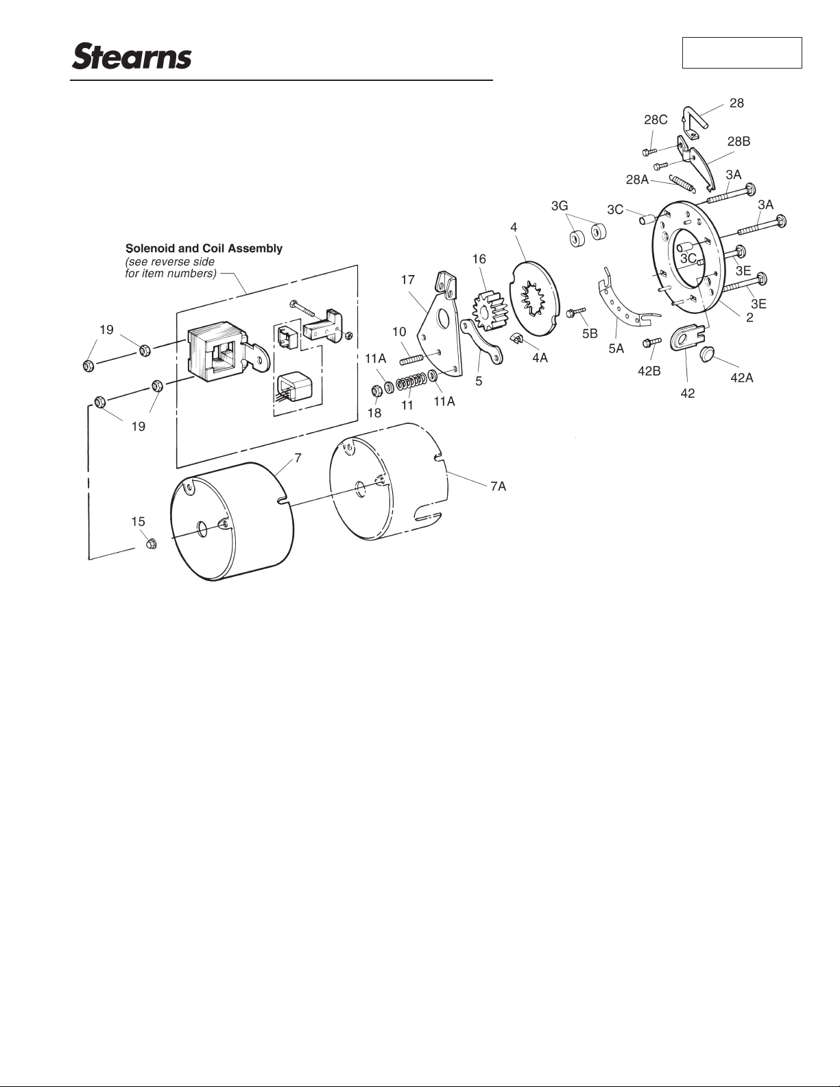
Figure 1
Installation and Service Instructions
for 48,100 Series Brakes (rev. A)
(Models 1-048-151, 1-048-161 and 1-048-171)
P/N 8-078-924-06
effective 2/23/04
Page 2
pressure spring force against the
stationary plate and friction disc, stopping
and holding the load.
Warning! Any mechanism or load held in
position by the brake should be secured
to prevent possible injury to personnel or
damage to equipment before any
disassembly of the brake is attempted or
the manual release lever is operated on
the brake.
When the motor is off and the load is to
be moved without energizing the motor,
the manual release lever can be rotated
90° away from the mounting face. This
removes the retarding torque from the
motor shaft, allowing the load to be
moved. The brake will remain in the
manual release position until the release
lever is returned manually to its
set
position, or until the brake is re-energized
electrically and the release lever returns
to its
set
position automatically.
Note: The motor should not be run with
the brake in the manual release position
to avoid overheating of friction disc.
I. General Installation Notes
Brake mounting can be in any position.
Brake is mounted with two 1/4” flat head
socket cap screws mounted 180° apart.
II. Installation Procedure
1. Remove housing nuts (15) and housing
(7) or (7A).
2. Remove hub (16) from brake and slide
onto motor shaft and key (not
furnished) to within 3/16” of motor
mounting surface. Torque both set
screws to 33 lb-in of torque.
Note: Check motor mounting face to be
sure NEMA dimensions of 0.004” T.I.R. on
concentricity and face run out are met.
Shaft run out is to be within 0.002” T.I.R.
Maximum shaft end float is 0.020”.
3. Attach brake to mounting surface by
sliding the brake friction disc (4) onto
hub (16), engaging without force. Brake
endplate (2) is to be tight against
mounting face.
4. Mounting the brake to the mounting
surface with two 1/4” flat head socket
cap screws (not furnished). Notches
are provided in the friction disc for
accessibility to the mounting holes.
Torque to screw manufacturer’s
recommendation based on materials
being used. Screw heads may not
protrude above wear surface. Brake
mounting can be in any position.
5. Verify solenoid air gap is 1/8”. Push in
plunger and allow it to snap out. Check
air gap. For vertical above motor
mounting, see Note in
Wear
Adjustment
Section. If adjustment is
required, see
Wear Adjustment.
6. See
Electrical Connection
for coil
connection.
7. Replace housing.
III. Torque Adjustment
The brake is factory set for nominal rated
torque. No further adjustment to increase
torque may be made. The approximate
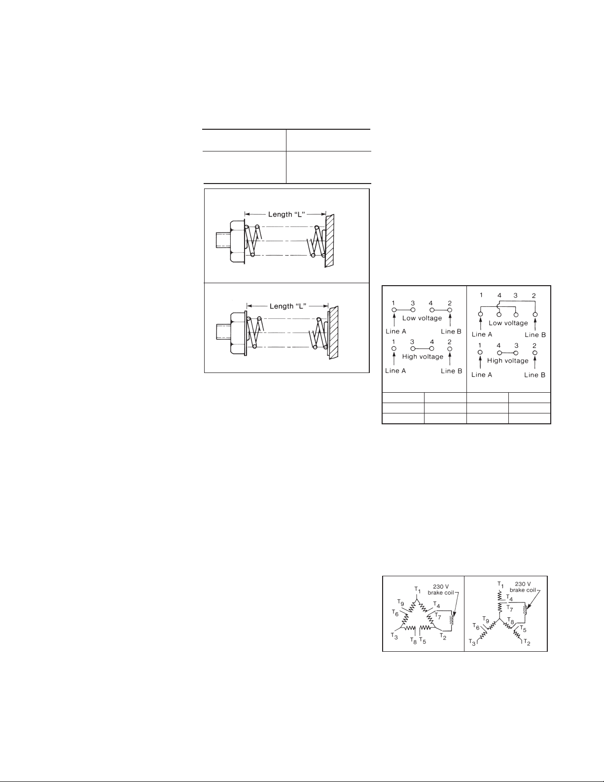
compressed torque spring length to
produce nominal rated torque is given in
Table A.
To increase stopping time on 3 and 6 lb-ft
brake, turn torque adjusting nuts (18)
counterclockwise equal amounts to
increase spring length. Spring studs
equipped with flats on the end are for a
wrench if the studs loosen during torque
adjustment. For the 3 and 6 lb-ft brakes,
one full turn on the nut will reduce the
nominal torque approximately 15%. Do
not reduce torque to less than 50% of
nominal rated. Torque for the 1.5 lb-ft
brake may not be reduced.
IV. Electrical Connection
CAUTION 1: Inverter Motor and Special
Control Systems. This brake contains
either a single phase AC coil or DC coil
that requires instantaneous power within
± 10% of rating at the coil. A separate
power source is required when this brake
is used in conjunction with a motor or
control system that limits voltage or
current input (i.e. inverter motors) or
causes a ramping of the power supply.
CAUTION 2: Class H coils with terminals.
Do not bend lead wire crimp connection
as this causes a fatigue in the metal
which may break under vibration.
Note 1: Brake coil connections described
here cover common motor connections.
For nonstandard motor or control
connections contact respective supplier or
Stearns Division.
Note 2: Be sure lead wires to coil are not
tight or pinched, and that leads will not be
rubbed by friction disc, trapped between
solenoid plunger and frame, caught
between lever arm and endplate, or by
linkage.
General
All coils are single-phase alternating
current (AC).
Single voltage coil connection
Connect coil (12C) to any two wires of a
single-phase or three-phase power source
of appropriate voltage. For operation with
a motor control, connect to any two motor
leads with correct voltage.
Dual voltage coil connection
Preconnect coil for appropriate high or
low voltage as shown in Figure 3. On
these coils observe the lead numbering
sequence for proper connections as
follows:
Connecting AC solenoid coils on dual
voltage 230/460 three-phase motors
To use a 230 volt coil (or a 230/460 dual
voltage coil connected for 230 volts) with
a 230/460 dual voltage three-phase
motor, the brake leads are connected
across two motor terminals as shown, or
other equivalent combinations. If a 230
volt brake coil is connected as shown in
Figures 4 or 5, the motor can be operated
on either 230 volts or 460 volts with no
effect on brake operation.
V. General Maintenance
1. Warning! Any mechanism or load held
in position by the brake should be
secured to prevent possible injury to
Table A
Brake Torque
(lb-ft)
Length “L”
(in.)
1.5
3
6
1
15/16
1-1/8
1-1/2 and 3 lb-ft
6 lb-ft
Figure 2
Figure 3
3 and 421High voltage
–2 and 41 and 3Low voltage
Tie Leads
Power Line BPower Line A
For
Figure 4 Figure 5
Page 3

personnel or damage to equipment
before any disassembly of the brake is
attempted or before the manual release
lever is operated on the brake.
2. Observe all cautions listed at the
beginning of this manual before
attempting to service brake.
3. Remove housing screws (15) and
housing (7) or (7A).
Wear adjustment
1. Normal friction disc wear will cause
solenoid air gap to become larger from
the original set 1/8” air gap. An
increase in stopping time and a slight
reduction in torque will consequently
occur. See Figure 6.
2. When the solenoid air gap increases to
1/4”, the brake must be adjusted. The
gap is measured between the mating
ground surfaces of the solenoid frame
and solenoid plunger.
Note: To measure air gap on brakes
mounted vertical above motor, push
plunger into frame until spring pressure is
felt. Holding firmly in this position,
measure air gap between mating (ground)
surfaces on solenoid frame and solenoid
plunger. If adjustment is made, check air
gap by again holding plunger as directed.
3. To decrease air gap, turn the wear
adjusting screw (10) clockwise until an
air gap of 1/8” minimum is attained.
To increase gap, turn screw
counterclockwise.
4. After adjustment, push in plunger and
allow it to snap out. Recheck air gap,
see Note.
5. Replace friction disc when wear area is
one half original disc thickness of 3/16”.
Friction disc replacement
1. Disconnect power source to brake.
2. Align friction disc (4) notches with the
two 1/4” flat head cap screws. Remove
the screws and slide entire brake off
motor and hub.
3. Remove housing support nut (19) and
solenoid mounting nut (19) from one
side of the solenoid mount. Slide
carriage bolt (sA) out the backside of
the endplate (2). Remove solenoid
spacer (3C) and shock pad (3G).
4. Slide old friction disc out the side of the
brake assembly.
5. Insert new friction disc between
endplate (2) and stationary plate (5).
Reassemble brake in reverse order of
Steps 2 & 3. Tighten the solenoid
mounting nut (19) to 15 lb-in to
compress the shock pad (3G).
Note: If solenoid buzz is noted, readjust
solenoid mounting nut (19) to “tune out”
the buzz.
6. See
Wear adjustment
. It may be
necessary to turn wear adjust screw
(10) CCW for clearance.
7. Repostion the housing support hot (19)
165" from the top of the housing bolt.
8. Replace housing.
9. Restore power to brake.
Coil or solenoid assembly replacement
1. Disconnect coil (12C) from circuit.
2. Cut the plastic wire tie holding the coil
leads onto the housing stud (18).
3. Remove housing and solenoid
mounting nuts (19) and lift solenoid /
coil assembly off the mounting bolts.
4. Remove plunger guide (82A) by lifting
out of top of solenoid frame. Coil (12C)
has a lock tab, located at top of coil
opposite lead wire side, which is
pressed against coil and coil is slid
sideways from solenoid frame.
5. For coil replacement, inspect and clean
solenoid assembly. Install the new coil
in original solenoid frame or original
coil in new solenoid frame with the lead
wires positioned as before. Install
plunger guide(s) in reverse order of (4).
5A. For solenoid assembly replacement,
remove plunger screw (9) and plunger
nut (9B). Install new plunger (29A)
with new plunger screw and nut.
6. Reassemble brake in reverse order of
Steps 1, 2 and 3. Tighten solenoid
mounting nuts (19) to 15 lb-in of torque
to compress the shock pad (3G).
Note: If solenoid buzz is noted, readjust
solenoid mounting nut (19) to “tune out”
the buzz.
7. Reposition the housing support hot (19)
165" from the top of the housing bolt.
8. Replace housing.
9. Restore power to brake.
VI. Troubleshooting
A. If brake does not stop shaft properly
or overheats, check the following:
1. Is brake manually released rather than
electrically released while motor is
running?
2. Is friction disc excessively worn,
charred, or broken?
3. Has hub become loose and shifted on
shaft?
4. Is hub clean, and does friction disc
slide freely?
5. Does stationary plate slide freely on
guide pins?
6. Are pressure springs improperly
assembled, or broken?
7. Is solenoid air gap adjusted correctly?
See
Wear Adjustment.
8. Does solenoid linkage move freely?
9. Is voltage supply at coil correct?
10. Are controls which govern start or
stop of braking cycle operating
properly?
Figure 6
Page 4

Copyright© 2000 by Rexnord Industries, Inc.
Rexnord Industries, Inc., Stearns Division, 5150 S. International Drive, Cudahy, Wisconsin 53110
(414) 272-1100 Fax: (414) 277-4364 www.rexnord.com
11. Is brake coil energized at same time
or prior to energization of motor, and
de-energized at same time or after
de-energization of motor?
12. Is stopping time more than one
second (rule of thumb) and/or is
application more than five stops per
minute? If so, consult factory. Check
thermal requirements of load versus
thermal rating of brake.
13. Replace friction disc when worn area
is one half of original thickness of
3/16”.
B. If brake hums, solenoid pulls in
slowly, or coil burns out, check the
following:
1. Voltage supply at coil versus coil rating
and connection.
2. Is solenoid air gap excessive?
3. Shading coils may be broken.
4. Plunger guides may be excessively
worn. Does solenoid plunger rub on
solenoid frame laminations?
5. Solenoid frame and plunger may be
excessively worn.
6. Is solenoid dirty?
7. Housing studs may have become loose
causing frame to shift and plunger to
seat improperly.
8. Does solenoid linkage move freely?
9. Check for excessive voltage drop in
motor line when motor is started.
Check wire gauge of supply line
against motor starting current and
solenoid inrush current. Measure
voltage drop at solenoid coil leads
during maximum inrush current
condition. To accomplish this, connect
voltmeter at brake coil. Insert a block of
wood, or other non-magnetic material,
between solenoid plunger and frame.
Block thickness should approximately
equal solenoid air gap. Energize motor
and brake simultaneously, take reading
and immediately shut down. (This is to
prevent motor, brake, or solenoid burn
up, since brake will be set during
procedure.)
C. If disc noise occurs, check:
1. If friction disc (4) becomes noisy, check
stabilizing spring (4A) to be sure it is
installed.
2. Check that the leaf spring (5A) is
supporting stationary plate (5). If
distorted, replace.
 Loading...