

Steam Weeding Four Wheel Hoe Instruction Manual
Four Wheel Hoe
Four Wheel Hoe Four Wheel Hoe
Four Wheel Hoe
Instruction Manual
Instruction ManualInstruction Manual
Instruction Manual
European Model
www.physicalweeding.com
© 2009 Steam Weeding Ltd.
© 2009 Steam Weeding Ltd.© 2009 Steam Weeding Ltd.
© 2009 Steam Weeding Ltd.

© 2009 Steam Weeding Ltd. www.physicalweeding.com Page 2
1. Contents
1. Contents 2
2. Introduction 3
3. Fitting farm and hoe to each other 3
4. Assembling your Four Wheel Hoe 4
4.1. Four Wheel Hoe components 4
4.1.1. Main frame 4
4.1.2. Wheels 5
4.1.3. Sight guide 6
4.1.4. Handles 6
4.2. Adjusting the hoe 7
4.2.1. Wheels: longitudinal positions 7
4.2.2. Handles: vertical and longitudinal positions 7
4.2.3. Hoe width 8
4.2.4. Sight guide 8
5. Tool attachment, setup and adjustment 8
5.1. Attaching tools 8
5.1.1. Tool setup: flat floor or a ‘depth setup board’ 9
1.1.1 Longitudinal position: parallel or staggared? 10
1.2 T hoes 10
5.1.2. Hoe blade lengths 10
5.1.3. Attaching the T hoes 11
1.2.1 Longitudinal position 11
1.2.2 Depth 11
5.1.4. Width / crop gap 12
5.2. Mini-ridgers 12
5.2.1. Attaching the mini-ridgers 12
5.2.2. Changing ridger blades and locking in position 13
5.2.3. Depth and crop gap 13
5.2.4. When not in use 13
6. Using your Four Wheel Hoe 13
7. Maintenance 14

© 2009 Steam Weeding Ltd. www.physicalweeding.com Page 3
2. Introduction
While the Four Wheel Hoe is straight forward to use, to get the best out of it requires an appreciation of
how knife blade hoes and soil ridging kills weeds, the design concepts behind the hoe and how to set it
up for your farm / holding. Therefore the time spent reading this manual will be well rewarded by
ensuring the Four Wheel Hoe is best set up for you.
Four Wheel hoes are manufactured by different engineers in different countries. Therefore there are
minor differences in the design and materials between countries. This means there will be some
differences between your machine and some of the photos in this manual, however, the fundamental
design remains the same. Steam Weeding Ltd. also reserves the right to make changes and
improvements to the design without prior notice.
3. Fitting farm and hoe to each other
Any form of mechanisation, even a hand hoe, imposes restrictions on farming systems. If all weeding is
done by hand pulling, crop plants can be placed in any position, as they often are in ornamental gardens,
as people have the flexibility to work around the plants. In comparison, if a hand hoe is used the space
between plants must be larger than the width of the hoe blade, otherwise it will not be possible to hoe
in-between the plants without killing some of them. As the size and complexity of machinery increases,
it imposes ever greater restrictions on the layout of crops plants, otherwise machines cannot function
efficiently. The Four Wheel Hoe is no different. To be the most effective, crop plants must be planted in
straight rows, with each row the same distance apart. If the crop rows are bent and/or not equidistant,
following them is much harder and the crop is more likely to be hoed by accident. As for any blade hoe,
accurate depth placement is essential for maximising weed kill, so if the soil surface is too uneven then
optimum depth control will be impossible. Similarly lots of plant residues, soil clods, large stones and a
rough tilth will hamper effectiveness. For best results a level and fine surface-soil-tilth is required that is
free of plant residues large enough that they may bind and/or block the weeding tools. Stones larger
than 5 cm / 2” may also significantly impede progress and should be removed by raking, or for larger
areas, a reverse action stone burier is recommended.
To ensure that crop rows are straight and evenly spaced, it is recommended to make a row ‘marking out
bar’. This can be as simple as a wooden batten with pegs, big nails or similar, sticking out of it to mark
the rows, and a handle to drag it up the planting bed as straight as possible, or a purpose built
implement e.g., Figure 1. This is preferable to using strings or the bout marking bars found on some
pedestrian seed drills. If a tractor is available, then making a marking out bar that can go on the tractor’s
three point linkage is highly recommended as this will produce the straightest rows more quickly and
accurately than a hand-pulled marker bar.
Figure 1. Adjustable manual marking out bar.
© 2009 Steam Weeding Ltd. www.physicalweeding.com Page 4
4. Assembling your Four Wheel Hoe
Your four wheel hoe is part assembled. The only tool required is a 19 mm (½”) spanner to complete
assembly which is included with your hoe.
4.1. Four Wheel Hoe components
There are four main parts of the Four Wheel Hoe: (1) main frame, (2) wheels, (3) handles and (4) the
sight guide. The tools that attach to the hoe are covered in section 5 on page 8.
The main frame consists of two identical ¾ meter long ‘toolbars’ connected to each other by two bottle
screws (also called turnbuckles) (Figure 3). The wheels bolt directly into the main frame, two at the front
and two at the rear, with a choice of three mounting positions at either end (Figure 6).
The handles attach to the main frame by the ‘handle clamps’ which allow the handles to pivot up and
down, which are in turn attached to the main frame by a ‘frame clamp’ (normally just called a ‘clamp’
except when needing to differentiate between them and the handle clamps) (Figure 7). The sight guide
(Figure 4) bolts into an empty hole in the front of the main frame (Figure 7). Figure 2 shows a fully
assembled Four Wheel Hoe.
It is recommended to put a drop of oil or grease on all the bolt threads prior to assembly. This is good
engineering practice as it allows them to be more firmly tightened and will reduce the chance of them
coming loose. It also makes doing them up quicker and easier!
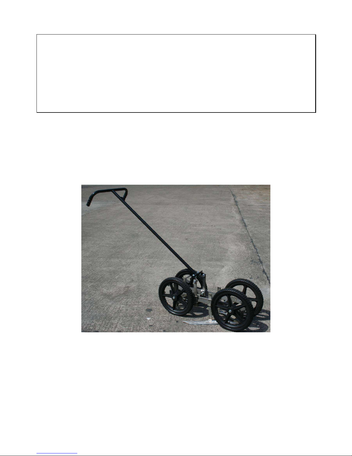
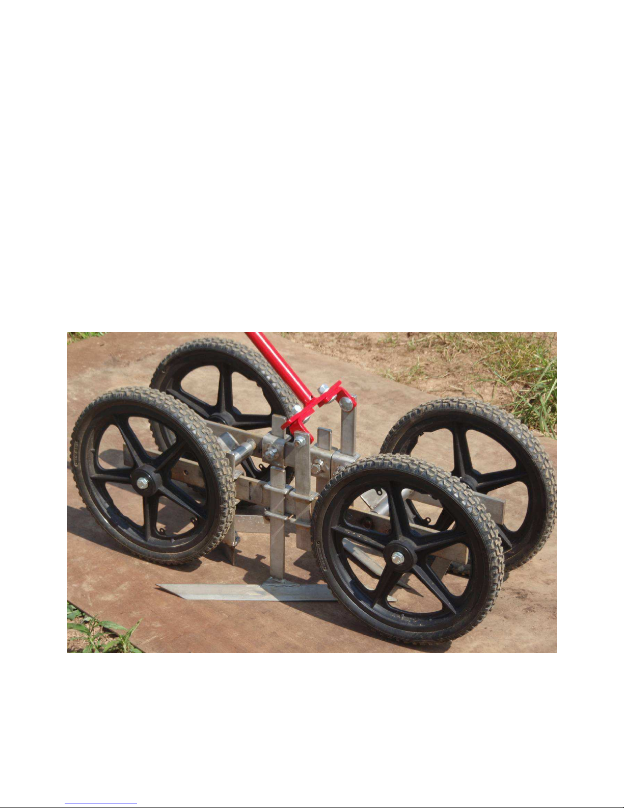
Figure 2. Fully assembled Four Wheel Hoe.
4.1.1. Main frame
The main frame comes pre-assembled. If the main frame is ever dismantled (by completely undoing the
bottlescrews), then the threaded bar will only go into one end of the bottlescrew body as one end has a
left-handed thread while the other has a right handed thread, i.e., the left handed threaded bar has to
be matched to the left hand threaded end of the bottlescrew body.
© 2009 Steam Weeding Ltd. www.physicalweeding.com Page 5
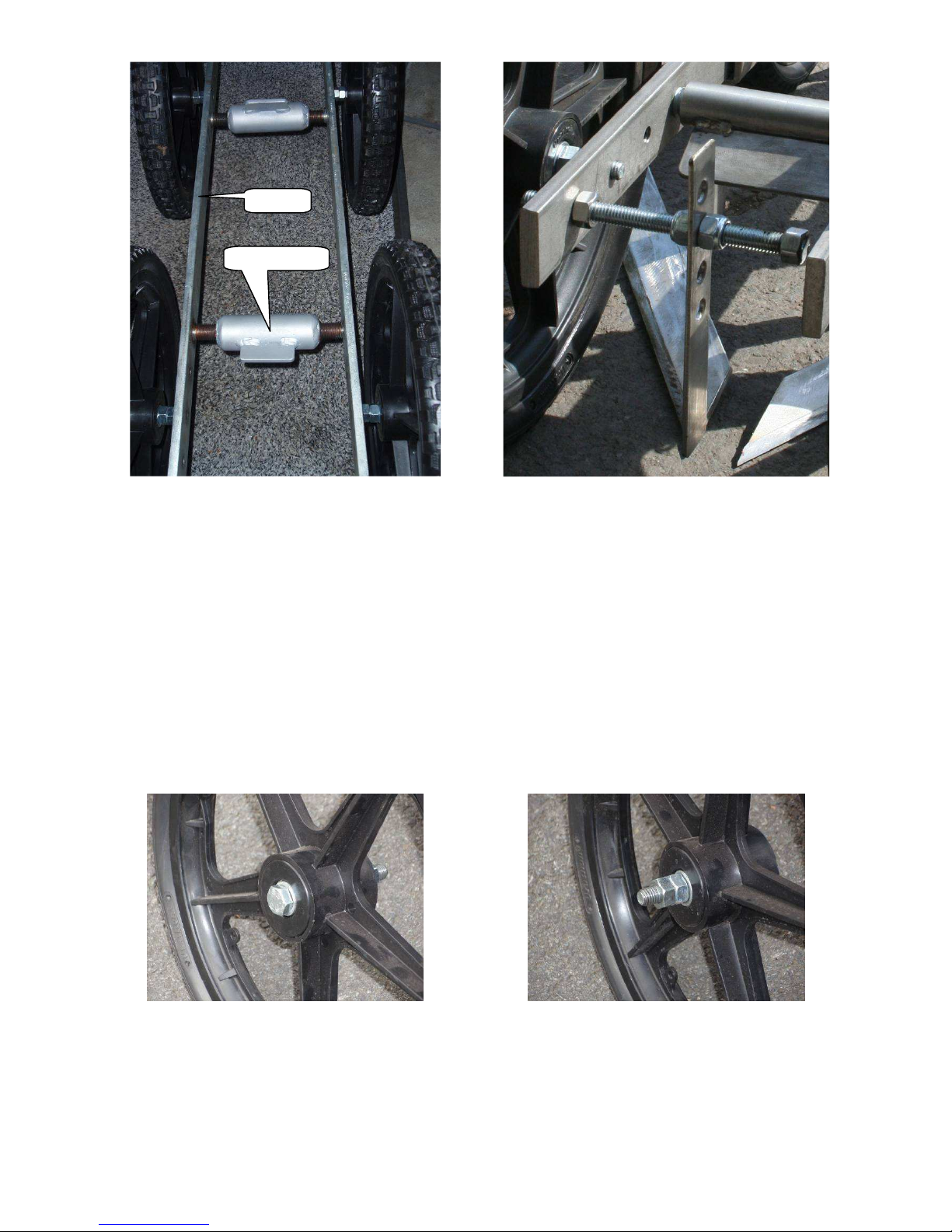
Figure 3. Main frame: Two long ‘toolbars’ connected by two
bottle screws
Figure 4. Sight guide.
4.1.2. Wheels
Next bolt the wheels into the threaded holes at either end of the main frame. The bolts should already
be fitted to the wheels, but if not use the 90 mm long fully threaded bolts (technically called a screw),
use flat washers on either side of the wheel axle hole and use two nuts to lock the bolt to the wheel (this
acts as a spacer). Then screw the bolt into the frame, making sure the nuts and attachment to the frame
are not so tight that it stops the wheels freely rotating, but tight enough so the wheels do not wobble or
otherwise feel loose (Figure 3 and Figure 5). To start with it is suggested that the rear pair of wheels are
fitted to the center pair of holes at one end of the main frame and the front wheels are bolted to the
inner most pair of holes (Figure 6). Having the rear wheels further towards the end of the frame helps
when manoeuvring the hoe on its rear wheels as it creates greater clearance between the hoe blades,
mini-ridgers and the ground.
Figure 5. Axle bolts for wheels showing washers on either side of the wheel, with two nuts on the bolt.
Toolbar
Bottlescrew
 Loading...