

Page 1
MODELS
W
H
I
S
P
E
R
Q
U
I
E
T
B
U
I
L
T
-
I
N
A
U
T
O
D
R
A
I
N
C
O
N
T
I
N
U
O
U
S
S
T
E
A
M
Q
U
I
C
K
S
T
A
R
T
4.5KW
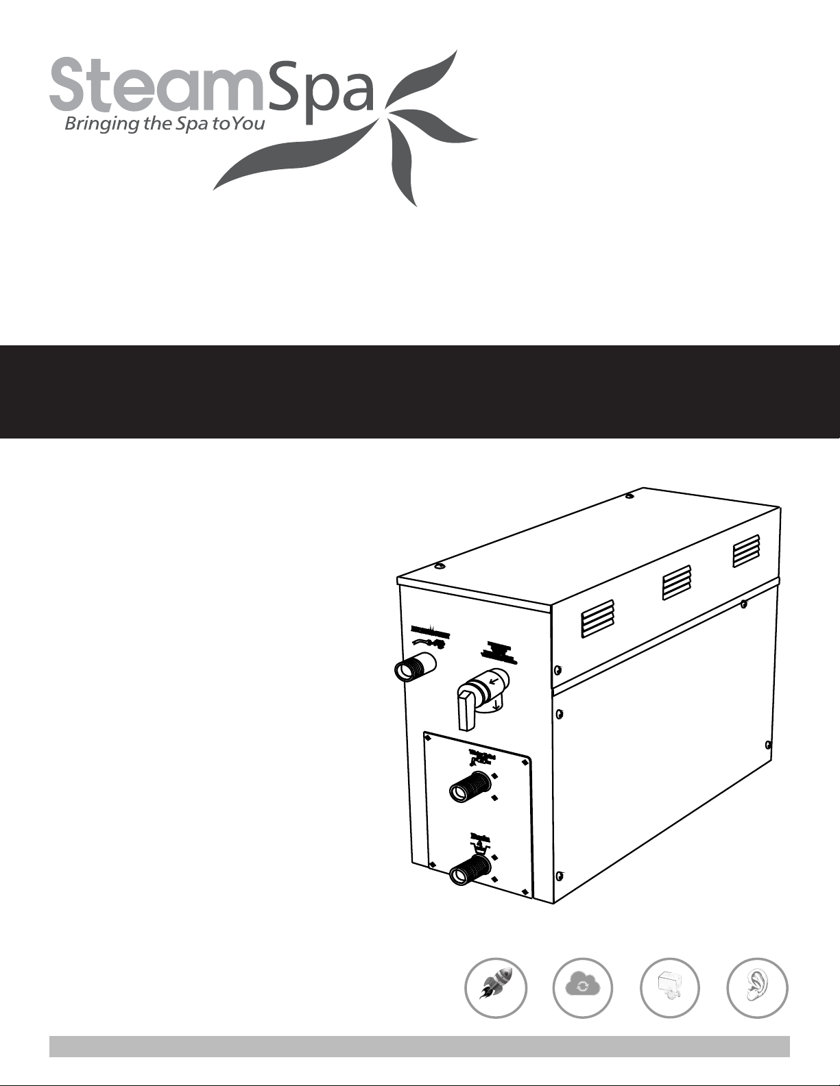
STEAM BATH GENERATOR USER GUIDE
BLACK SERIES
6KW
7.5KW
9KW
10.5KW
12KW
Steam Spa PHONE: 800-856-0172 FAX: 866-560-1060 http://steamspa.com [email protected]
V2.1
Page 2
Steam Spa PHONE: 800-856-0172 FAX: 866-560-1060 http://steamspa.com [email protected]
Page 3
TABLE OF CONTENTS
PROLOGUE ....................................................................................................................... 4
USER INSTRUCTIONS ......................................................................................................... 4
CHOOSING THE RIGHT LOCATION .......................................................................................... 4
INSTALLATION DRAWING OF STEAM GENERATOR ..................................................................... 5
PLUMBING INSTALLATION ................................................................................................... 8
STEAM GENERATOR SPECIFICATIONS ................................................................................... 10
ELECTRICAL REQUIREMENTS ............................................................................................. 11
ASSEMBLY GRAPH FOR POWER WIRE .................................................................................. 12
INSTALLATION OF THE TOP LIGHT ........................................................................................ 14
STEAM GENERATOR DISSECTION DIAGRAM ........................................................................... 15
CARE & USE FOR THE CONTROL PANEL ................................................................................ 16
CONTROLLER BOX CONTENT .............................................................................................. 16
CONTROL PANEL INSTALLATION INSTRUCTIONS ..................................................................... 17
TESTING THE MACHINE ..................................................................................................... 18
CONTROL PANEL DIAGRAM ................................................................................................ 18
CONTROL PANEL OPERATION ............................................................................................. 19
STEAM GENERATOR MAINTENANCE ..................................................................................... 25
TECHNICAL PARAMETERS .................................................................................................. 29
WIRING DIAGRAMS .......................................................................................................... 30
IMPORTANT!
PRIOR TO INSTALLATION, LET WATER RUN THROUGH THE WATER PIPE TO CLEAN ANY POSSIBLE
DEBRIS BEFORE CONNECTING THE GENERATOR.
INSTALLATION & USER GUIDE
SteamSpa PHONE: 800-856-0172 FAX: 866-560-1060 http://steamspa.com [email protected]
Page 3
Page 4

PROLOGUE
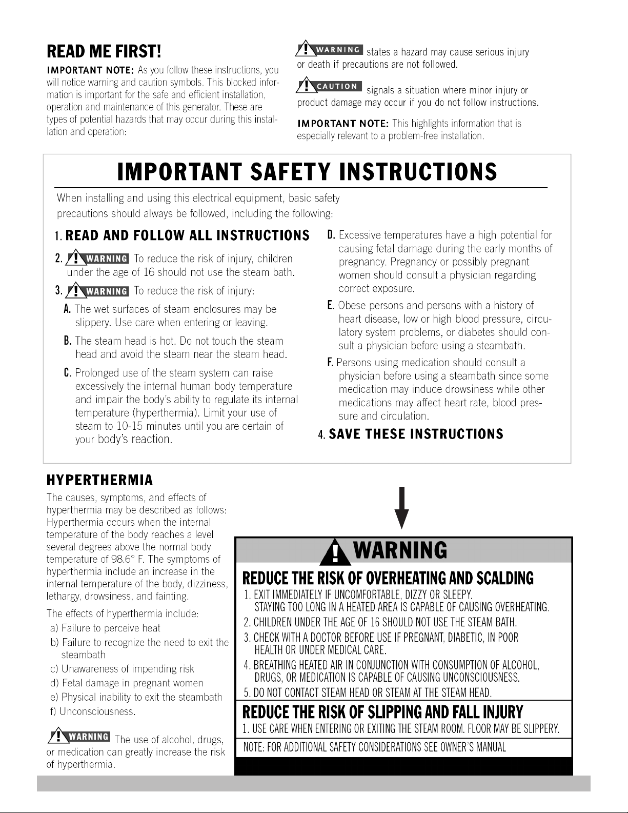
Thank You for choosing SteamSpa for health, beauty and relaxation. Now you can enjoy your own private sanctuary in the comfort
of your own home. Let your stress melt away as you relax in your state of the art Steam Room.
For Centuries people have recognized the health benefits of saunas. Leave your stress behind and enter a world of total relaxation,
ridding you of pain, toxins, and sore muscles as well as increasing your blood circulation etc., leaving your skin glowing. Besides
these physical effects, a SteamSpa Session will leave you totally relaxed by providing you a peaceful and relaxing environment
away from all.
Our advanced technology, engineering, and product development provides Steam Generators that enhance the lifestyles of people
throughout the world. SteamSpa is continuously refining, updating and developing their products assuring the optimum quality
and performance of their products. Working with the industries top engineers we have developed the most efficient, dependable
and highest quality products.
USER INSTRUCTIONS
1. Check for visible damages upon delivery of Generator. Any damages to packaging should be reported immediately to shipping
company delivery representative and SteamSpa’s Customer Service Dept.
2. Check model and accessories are correct, including voltage input. Any discrepancies are to be reported to SteamSpa’s
Customer Service Dept. within 48 hours of delivery.
3. Read installation instructions in detail for a secure and effective installation of SteamSpa generators.
4. SteamSpa recommends the use of a licensed plumber and electrician for proper installation of SteamSpa generators.
5. SteamSpa shall not be responsible for product damage or malfunction caused by self-installation or installation procedures
which do not comply with user manual.
6. SteamSpa generators should be installed indoors only.
CHOOSING THE RIGHT LOCATION
1. The generator should be less than 25ft from the steam room for best performance.
2. The steam generator should not be installed in the steam room
3. Do not install outdoor or in any places that will influence the performance of the machine by the environment.
4. Do not install in a frigid location or any places where the water will freeze.
5. Do not install near flammable chemicals.
6. Install in a dry place where the ventilation is good.
7. Install an exhaust fan outside of the steam room for the excess steam to be expelled from the shower room.
8. The steam generator has a hanging groove for wall installations..
9. Both sides and the top of the steam generator need to reserve at least 12 inches space.
10. The area where the machine is installed must be easily cleaned up and convenient for the disassembly of the machine.
11. The installation area must be convenient for the steam generator draining system.
12. The steam tube, safety valve, drain valve, water tube and steam outlet remain very heated after the steam generator has
stopped working for some time.
13. The controller panel should be installed away from the steam head to avoid false readings,please read the instructions for the
controller’s installation and operation.
Page 4
INSTALLATION & USER GUIDE
SteamSpa PHONE: 800-856-0172 FAX: 866-560-1060 http://steamspa.com [email protected]
Page 5
INSTALLATION DRAWING OF STEAM GENERATOR
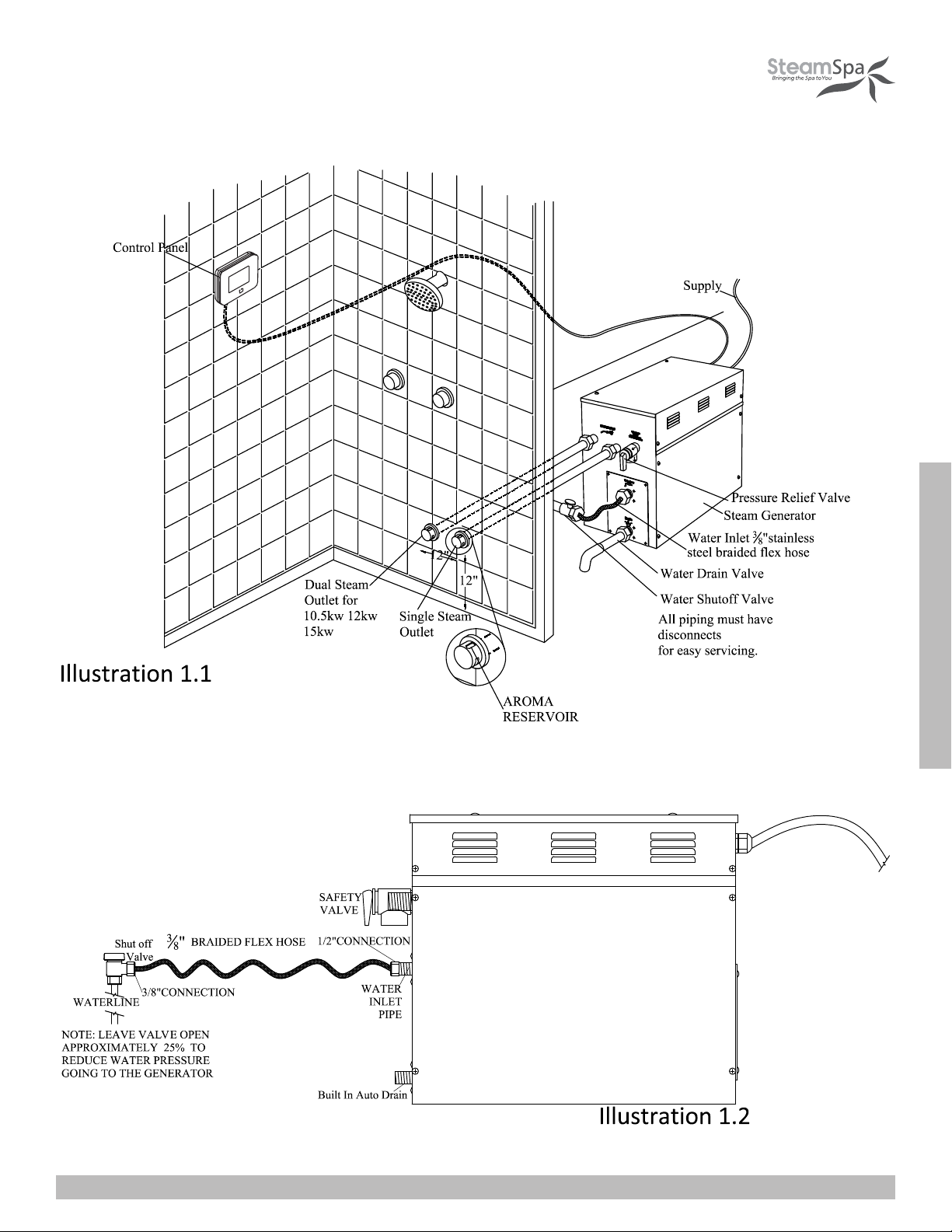
ATTENTION! The drawing is only for explanation purposes. As for practical design of steam room, please consult with a qualified
designer, architect or builder.
Page 5
INSTALLATION & USER GUIDE
SteamSpa PHONE: 800-856-0172 FAX: 866-560-1060 http://steamspa.com [email protected]
Page 6
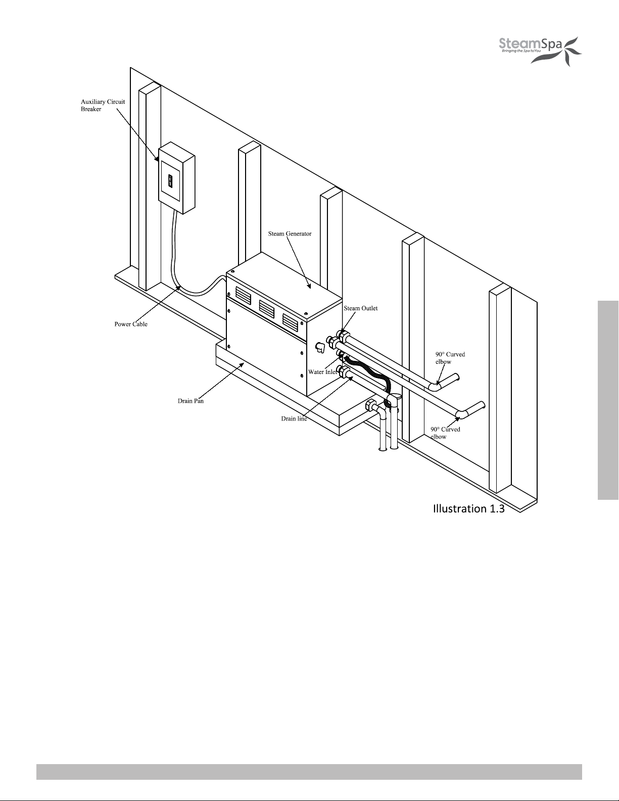
ATTENTION! The drawing is only for explanation purposes, please consult with a qualified designer, architect or builder.
IMPORTANT! All pipe connections should have unions and adapters for easy disconnect.
INSTALLATION & USER GUIDE
Page 6
SteamSpa PHONE: 800-856-0172 FAX: 866-560-1060 http://steamspa.com [email protected]
Page 7

110
ATTENTION! The illustration is just an example; the practical installation must comply with the nation’s electrical criteria, and be
done by a professional electrician.
The steam generator maybe installed in these location.
1. In closet located behind the shower.
2. In Attic
3. In basement etc.
INSTALLATION & USER GUIDE
ATTENTION! If the installation of the steam generator will be more then 10 to 15 feet away from the steam room. It is
recommended to increase the size of the generator 1 or 2 kilowatts higher to increase the steam flow.
SteamSpa PHONE: 800-856-0172 FAX: 866-560-1060 http://steamspa.com [email protected]
Page 7
Page 8

PLUMBING INSTALLATION
WARNING! The installation of all water supply lines should be in accordance to all national and local codes by a licensed plumber.
1. Use unions when connecting pipes.
2. Use brass pipes or copper pipe only.
3. Do not use black and galvanized or PVC pipes.
WATER SUPPLY PIPE (1/2’’)
1. Connect hot water or cold water pipes. However it should not exceed 160F.
2. Install a shut off valve in the water supply line.The shut off valve should be installed in a place where it is easily accessible in
case of an emergency.
3. Flush the water supply line completely before connecting the water pipe to the steam generator, to remove any sediments in
the water.
4. Use a 3/8” steel braded flex hose with a shut off valve to connect the main waterline to the generator. See page 5 illustration
1.2.
5. The shut off valve should be open approximately 25% to reduce water pressure to the generator. The water pressure to the
generator should be between 15 to 20 PSIG if necessary, decrease the pressure accordingly.
6. It is highly recommended to install a pressure reducing valve to reduce the water pressure between 15 to 20 PSI.
STEAM PIPE (3/4’’)
1. Do not install any stop valves in the steam pipes. The steam can never be obstructed.
2. Install a ¾” copper pipe between the steam generator and the steam nozzle for all generators, except the 4.5KW which
requires a ½” copper pipe.
3. If needed, the heat insulation material used to insulate the steam pipe should be resistant to temperatures as high as 240F or
higher.
4. The shorter the distance, the better. Use curved elbows when connecting pipes to allow the steam to flow smoothly through
the steam pipe.
STEAM HEAD (3/4’’)
ATTENTION! Steam Head and the steam outlet gets very hot, try to avoid installing the steam head in a position which will easily
come into contact with the person bathing.
1. Install the steam head approximately 12 inches above the ground floor. If the steam room material is acrylic or non-heatresistant sheet, please consult with material manufacturer about steam room applications.
2. The steam head outlet should be installed face down. To prevent scalding bather with steam or water.
ATTENTION! Tighten steam head by hand. Do not use a spanner or other tools, use a little soap water and soft sponge to wipe,
and do not use erosive chemical solutions or crude cleaning tools.
IMPORTANT!
1. Please consult manufacturer of materials like acrylic, fiber glass or other anti-heat sheet about the installation of the steam
head.
2. In the entire steam room, it is required that steam does not leak out. The pipes, its accessories and the holes should be air
proof by applying sealant so that no steam will enter the holes in the wall.
INSTALLATION & USER GUIDE
SteamSpa PHONE: 800-856-0172 FAX: 866-560-1060 http://steamspa.com [email protected]
Page 8
Page 9

DRAINPIPE (1/2’’)
ACCORDING TO THE NATIONAL AND LOCAL PLUMBING CODES: The steam generator drain valve should be equipped with
a drainpipe. The steam generator drains the water by gravity.Check local code requirements for drain valves. Do not connect the
safety valve or steam line to drain line.
SAFETY VALVE (3/4’’)
1. Safety valve is an automatic system that is actuated by pressure in order to prevent steam pressure increasing in the interior
of the generator .
2. The pressure limit range of the safety valve is 15 PSIG and the pressure will begin to decrease if pressure should come over
this value.
3. If it is allowed by local codes, provide the safety valve with exterior drainpipe.
4. Do not dismantle the pressure relief valve while generator is in operation..
5. To maintain the proper automatic operation of the safety valve, make sure the safety valve connection pipe is smooth.
Page 9
INSTALLATION & USER GUIDE
SteamSpa PHONE: 800-856-0172 FAX: 866-560-1060 http://steamspa.com [email protected]
Page 10
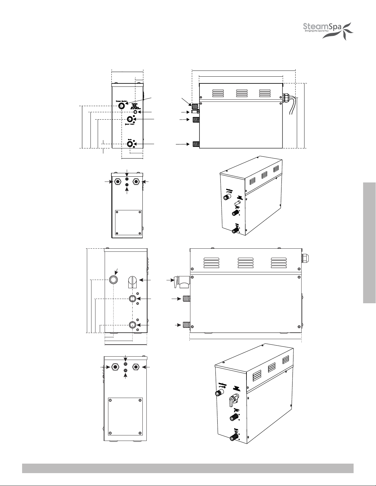
STEAM GENERATOR SPECIFICATIONS
20 6m m
18 8m m
15 1m m
Power wi re hol e
142mm
43mm
32mm
62mm
72mm
Fuse for wire power supply
C on tr oll e r w ir e
and l ight wire hole
Fuse for wire
power supply
St eam outlet
Sa fet y valve
Wate r i nlet
Wate r
drainage
395mm
304mm
302mm
266 mm
4.5kW
37 0mm
26 0m m
Pow er w ire hole
Steam outlet
18 0mm
30mm
30 mm
10 0m m
16 0m m
Fus e for wire powe r suppl y
Fuse for wire
power supply
S a f e ty
valve
Wat er inl et
Wat er drai nage
C on tro lle r wire
an d lig ht wi re
hole
6kW/7.5kW/9kW
INSTALLATION & USER GUIDE
40 0m m
SteamSpa PHONE: 800-856-0172 FAX: 866-560-1060 http://steamspa.com [email protected]
Page 10
Page 11
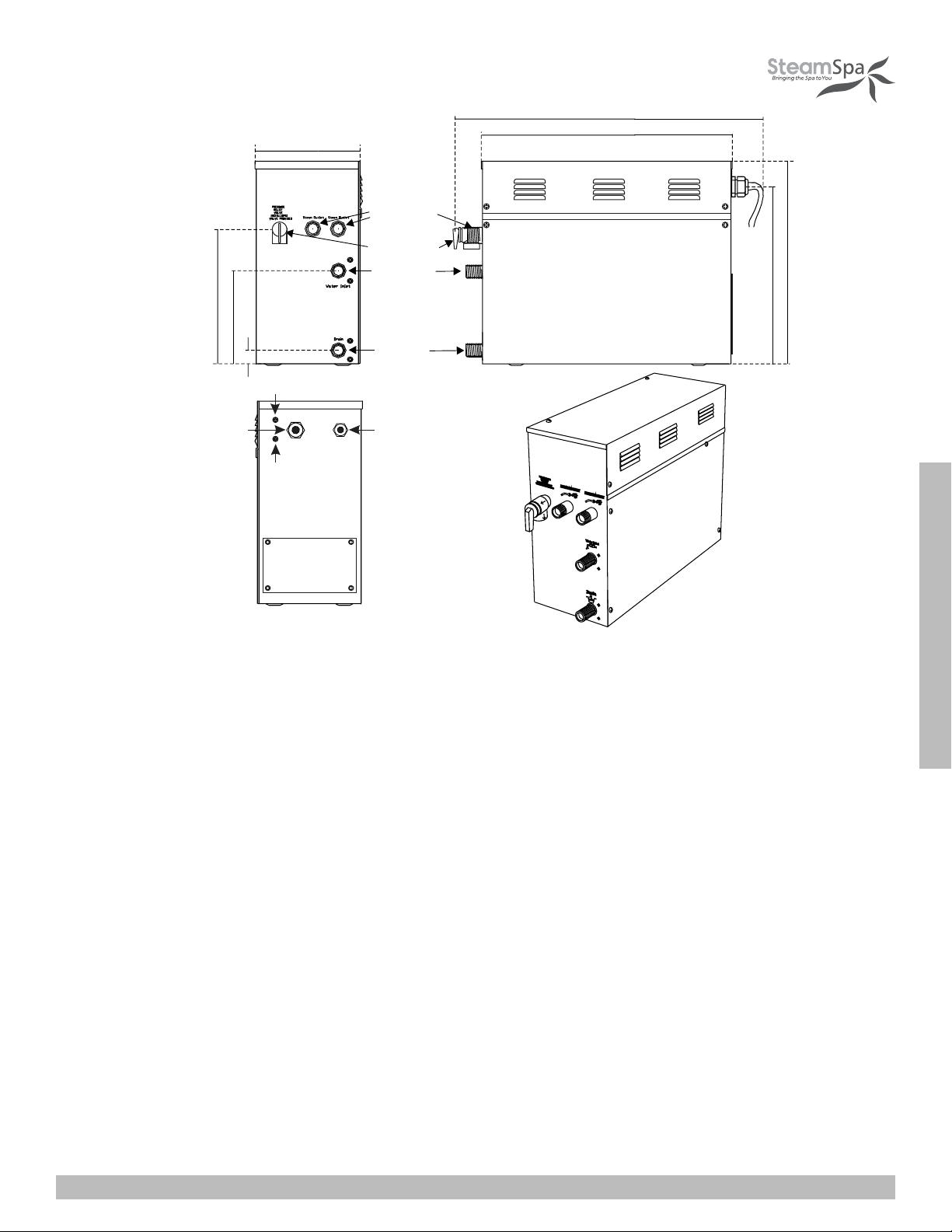
234mm
273mm
34mm
183mm
Fus e for wire power su pp ly
Steam outlet
Safety valve
Water inlet
Water
dr ainag e
535mm
435mm
35 0mm
38 5mm
Power wir e ho le
Fus e for wire
po wer sup ply
Co ntr oller wir e and
ligh t wire h ole
10.5kW /12k W/15kW
ATTENTION! To facilitate maintenance, keep the steam engine clean. If the information provided is limited, do not operate on the
pipeline and electric equipment arbitrarily as shown in the figure for proportion.
ELECTRICAL REQUIREMENTS
ELECTRICAL SUPPLY CIRCUITRY
1. Test the voltage of the power supply and make sure suitable voltage is used for the steam generator.
2. Insulated copper wire should be used with an anti-heat temperature of 90 C and a specified voltage of 300V. Refer to national
or local electricity consumption code for the specifications. Refer to the ammeter for the ampere.
3. Connect suitably sized equipment grounding wire into the ground terminal.
4. All the connections must be in accordance with national and local electricity consumption codes and be installed by
professional electricians.
INSTALLATION & USER GUIDE
SteamSpa PHONE: 800-856-0172 FAX: 866-560-1060 http://steamspa.com [email protected]
Page 11
Page 12
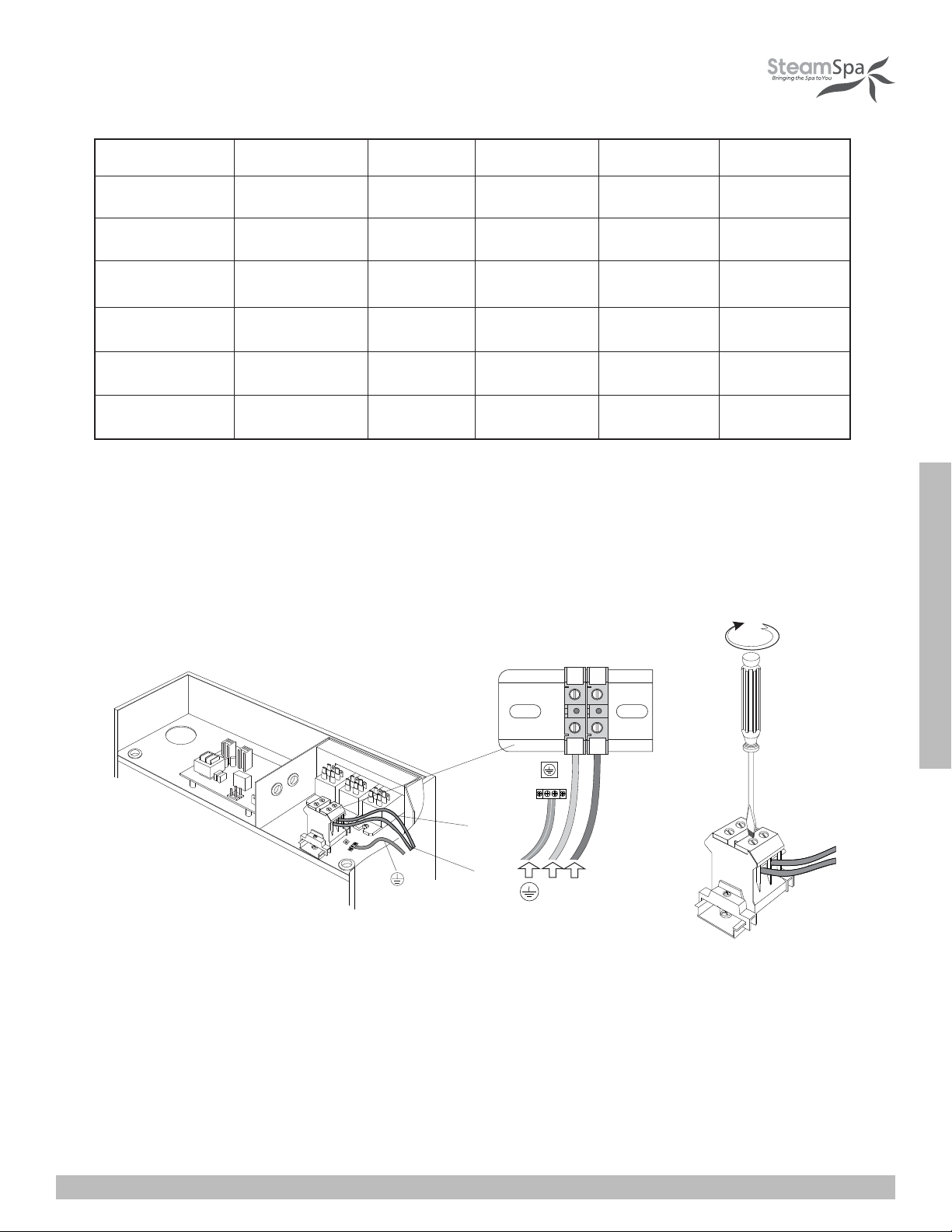
Ampere Meter
Ty p e Power KW
Ap p licab le s pace o f
the room (c u.Ft . *)
E l e c t r i c i t y
supply (1PH)
E l e c t r i c
current (A)
Spe ci fi cati ons for
power wire (AWG)
S450
S600
S750
S900
S1050
S1200
90
150
225
300
450
4.5 240V
6
7.5
9
10.5
12
240V
240V
240V
240V 44 6400
240V
240V
19
25
32
38
50
12
10
8
8
6
The data provided above is for 240V single-phased motors. Install an independent circuit breaker between supply line and steam
generator. Install a power disconnect within sight of steam generator to cut-off power when not in use.
ASSEMBLY GRAPH FOR POWER WIRE
Po wer co nnectio n term in al
L1 L2
L2
L1
L1
L2
Ground Hot
( 4 .5 - 1 2k W )
( 2 4 0 V ~ 1PH)
ATTENTION! To avoid damage to the equipment, do not connect electric current directly to heating elements.
WARNING! This graph is for explanation only. For actual installation, refer to national and local electricity consumption codes by
professional electricians.
Page 12
INSTALLATION & USER GUIDE
SteamSpa PHONE: 800-856-0172 FAX: 866-560-1060 http://steamspa.com [email protected]
Page 13
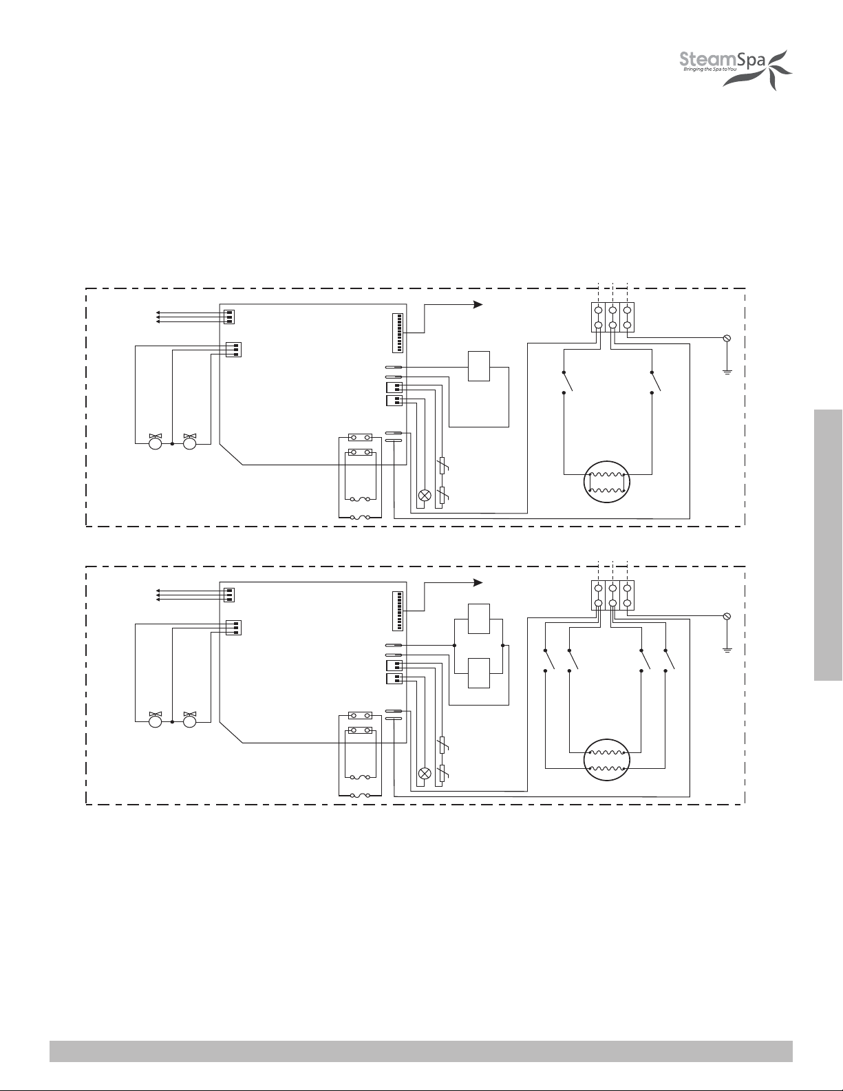
WIRING DIAGRAM
S600
Su p ply
Wa ter Le ve l Se nsor
Red ( S h o rt P i n )
Bl ac k (L o n g Pi n )
Yel l o w ( Mi d d l e P i n )
B la ck
R ed
Yellow
R ed
Bl a ck
Re d
T o C ont rol P an e l
J1
L1 G
L2
Ter m i na l B l oc k
Ye llow / G re en
Bla ck
J1-1
Red
J1-2
S S
Fill water valve
Wa ter Le ve l Se nsor
Red ( S h o rt P i n )
Bl ac k (L o n g Pi n )
Yel l o w ( Mi d d l e P i n )
S S
Fill water valve
R ed
Drain water valve
B la ck
Drain water valve
White
Black
B la ck
Red
Red
Red
Red
S450
B la ck
Black
Red
R ed
Su p ply
L1 G
T o C ont rol P an e l
J1J2
R ed
Yellow
Red
Red
Red
Red
Bl a ck
Black
Re d
White
B la ck
B la ck
Black
J1-1
Black
L2
Ter m i na l B l oc k
Ye llow / G re en
INSTALLATION & USER GUIDE
Blac k
J2-1
Black
Red
Red
J2-2
J1-2
Red
Red
R ed
SteamSpa PHONE: 800-856-0172 FAX: 866-560-1060 http://steamspa.com [email protected]
Page 13
Page 14
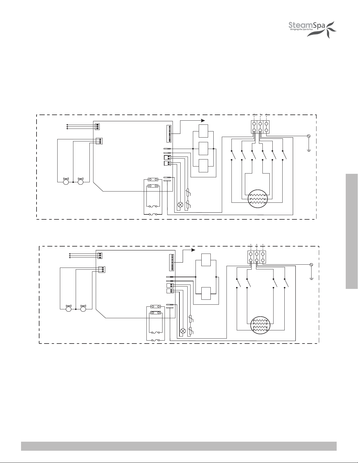
WIRING DIAGRAM
J1-1
J2-1
J2-2
J1-2
J1J2
S S
L1 G
S600
Su p ply
Red
Black
R ed
B la ck
Black
L2
Red
Red
T o C ont rol P an e l
Fill water valve
Drain water valve
Ter m i na l B l oc k
Ye llow / G re en
R ed
B la ck
Re d
Black
White
Bl a ck
Yellow
R ed
B la ck
Red
Red
Red
Red
Wa ter Le ve l Se nsor
Red ( S h o rt P i n )
Bl ac k (L o n g Pi n )
Yel l o w ( Mi d d l e P i n )
Su p ply
S750 S900
Blac k
Red
Black
J1-1
J1-2
J1
S S
L1 G
S450
Su p ply
Red
R ed
B la ck
Black
L2
Red
T o C ont rol P an e l
Fill water valve
Drain water valve
Ter m i na l B l oc k
Ye llow / G re en
R ed
B la ck
Re d
Black
White
Bl a ck
Yellow
R ed
B la ck
Red
Red
Red
Red
Wa ter Le ve l Se nsor
Red ( S h o rt P i n )
Bl ac k (L o n g Pi n )
Yel l o w ( Mi d d l e P i n )
Bla ck
Wa ter Le ve l Se nsor
Red ( S h o rt P i n )
Bl ac k (L o n g Pi n )
Yel l o w ( Mi d d l e P i n )
Wa ter Le ve l Se nsor
Red ( S h o rt P i n )
Bl ac k (L o n g Pi n )
Yel l o w ( Mi d d l e P i n )
R ed
S S
Fill water valve
R ed
S S
Fill water valve
B la ck
Yell ow
Drai n water valve
B la ck
Drain water valve
Red
Red
Red
Red
R ed
Red
Blac k
White
Black
B la ck
T o C ont rol P an e l
J1J2J3
Black
B la ck
Black
J1-1
J2-1
J3-1
Black
Black
Black
G
L1L2
Ter m i na l B l oc k
RedBlack
J3-2
Red
Red
J2-2
Red
Ye llow / G re en
Red
J1-2
Red
R ed
R ed
Bl a ck
Black
Re d
White
T o C ont rol P an e l
B la ck
Yell ow
Red
Red
Red
Red
Su p ply
G
L1
L2
J1J2
B la ck
Black
Black
J1-1
J2-1
Black
Black
Ter m i na l B l oc k
Ye llow / G re en
Red
Red
J2-2
J1-2
Red
Red
R ed
INSTALLATION & USER GUIDE
S1050
S1200
SteamSpa PHONE: 800-856-0172 FAX: 866-560-1060 http://steamspa.com [email protected]
Page 14
Page 15
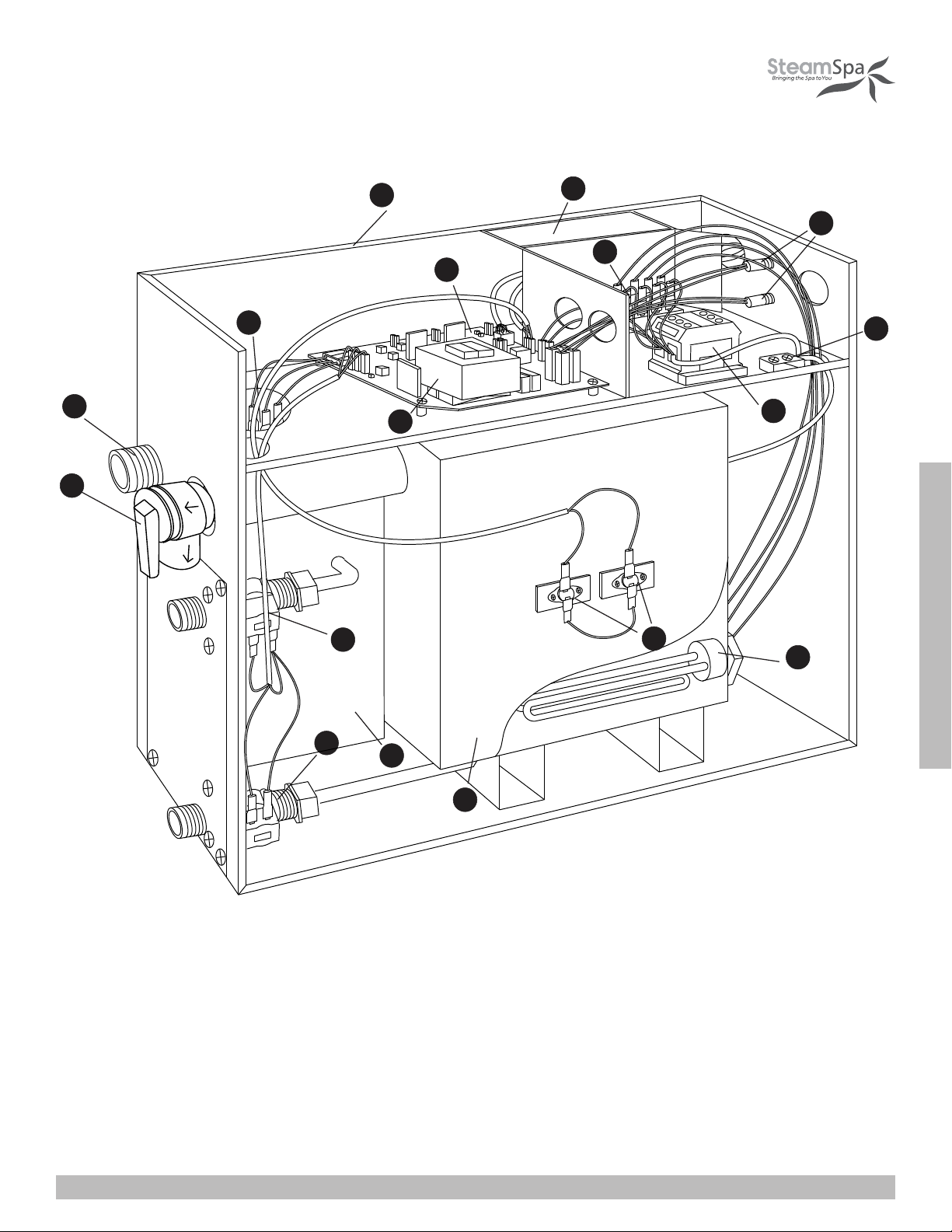
STEAM GENERATOR DISSECTION DIAGRAM
1
3
17
4
12
5
6
2
14
16
15
13
11
10
1. ENCLOSURE
2. INSULATION BRACKET
3. CIRCUIT BOARD
4. STEAM OUTLET
5. PRESSURE RELIEF VALVE
6. WATER FILL VALVE
7
8
9
7. WATER DRAIN VALVE
8. SUBSIDIARY WATER TANK
9. MAIN WATER TANK
10. HEATING ELEMENT
11. 221 F HI-LIMIT
12. TRANSFORMER
INSTALLATION & USER GUIDE
13. TERMINAL BLOCK
14. FUSE
15. GROUND WIRE CONNECTOR
16. RELAY
17. WATER LEVEL SENSOR
Page 15
SteamSpa PHONE: 800-856-0172 FAX: 866-560-1060 http://steamspa.com [email protected]
Page 16
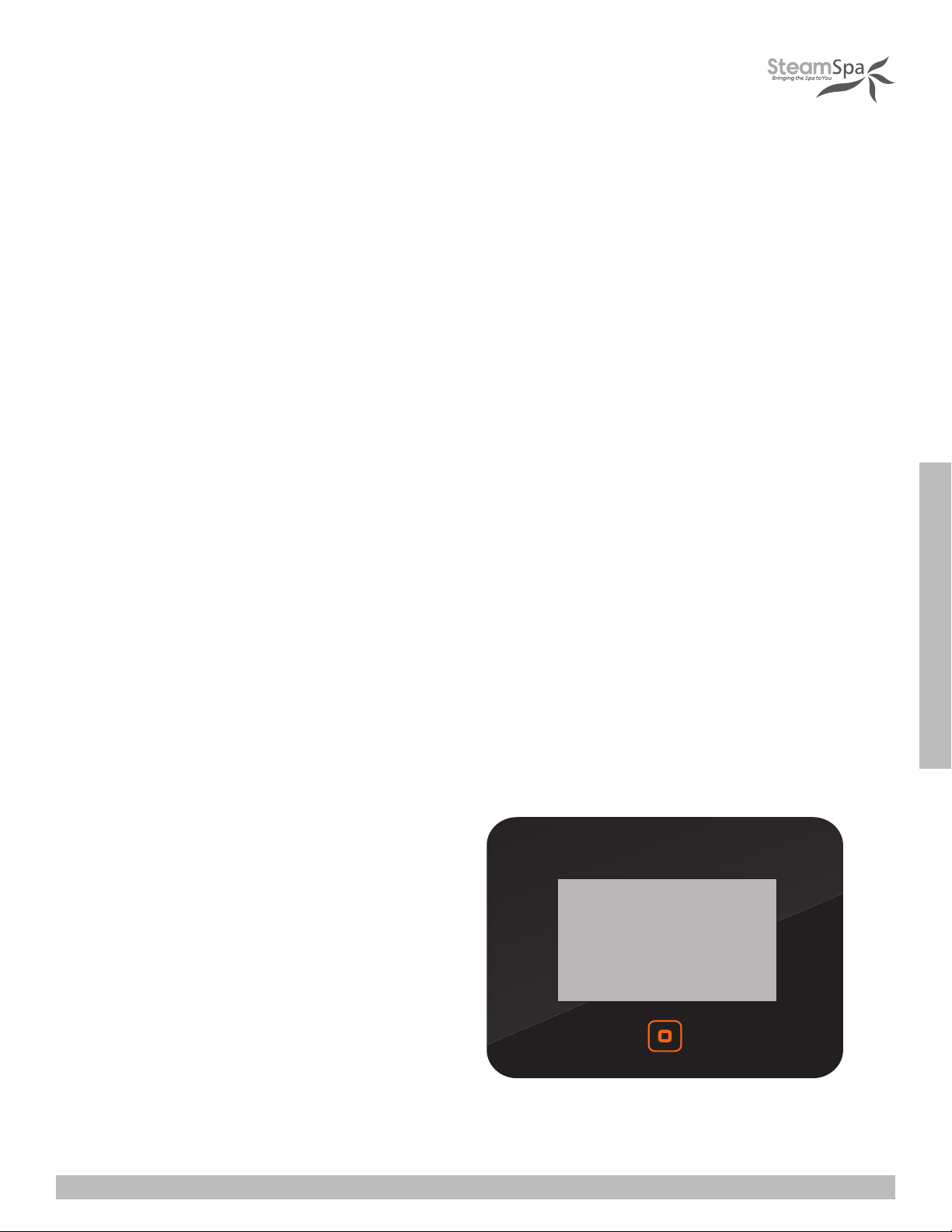
CARE & USE FOR THE CONTROL PANEL
1. Use soft cloth with a little soap water to clean the control panel.
2. Do not use crude cleaning tools.
3. If the decorating facade is damaged, contact service electrician to change it.
Do not install any SteamSpa controls without reading and understanding the SteamSpa generator Installation and Instruction
manual. Failure to read and understand these instructions will result in inoperative control, generator, hazardous overheating, and/
or inadequate heating of the steam room.
Do not route control wiring inside or close to power lines conduit, hot water or steam piping. Doing so may result in an inoperative
control, generator, and/or hazardous installation.
Do not install SteamSpa controls with other than SteamSpa compatible steam generators. Doing so may result in possible
generator damage or inoperative installation.
Single Control Panel with Temperature sensor must be installed inside bathing area 5 feet above floor. Do not install Control
directly above Steam Head or below shower head but rather in the seating area on a vertical wall. Doing so may result in improper
temperature reading and/or inoperable control.
Turn power to the steam generator off before connecting the control to the generator. Failure to turn the power off generator prior
to connecting controls will result in an inoperable control.
Discontinue use of the steam generator or control if the steam generator is damaged. Continue to do so may result in an
inoperative or hazardous installation.
CONTROLLER BOX CONTENT
• One (1) SteamSpa Black Control Console
• Two (2) Chroma Color Light
• One (1) LED White Light
• Two (2) Shower Speakers with Grills
• One (1) Rim Extension
• One (1) Control Box
• Four (4) Extension Cables
• User guide
INSTALLATION & USER GUIDE
SteamSpa PHONE: 800-856-0172 FAX: 866-560-1060 http://steamspa.com [email protected]
Page 16
Page 17
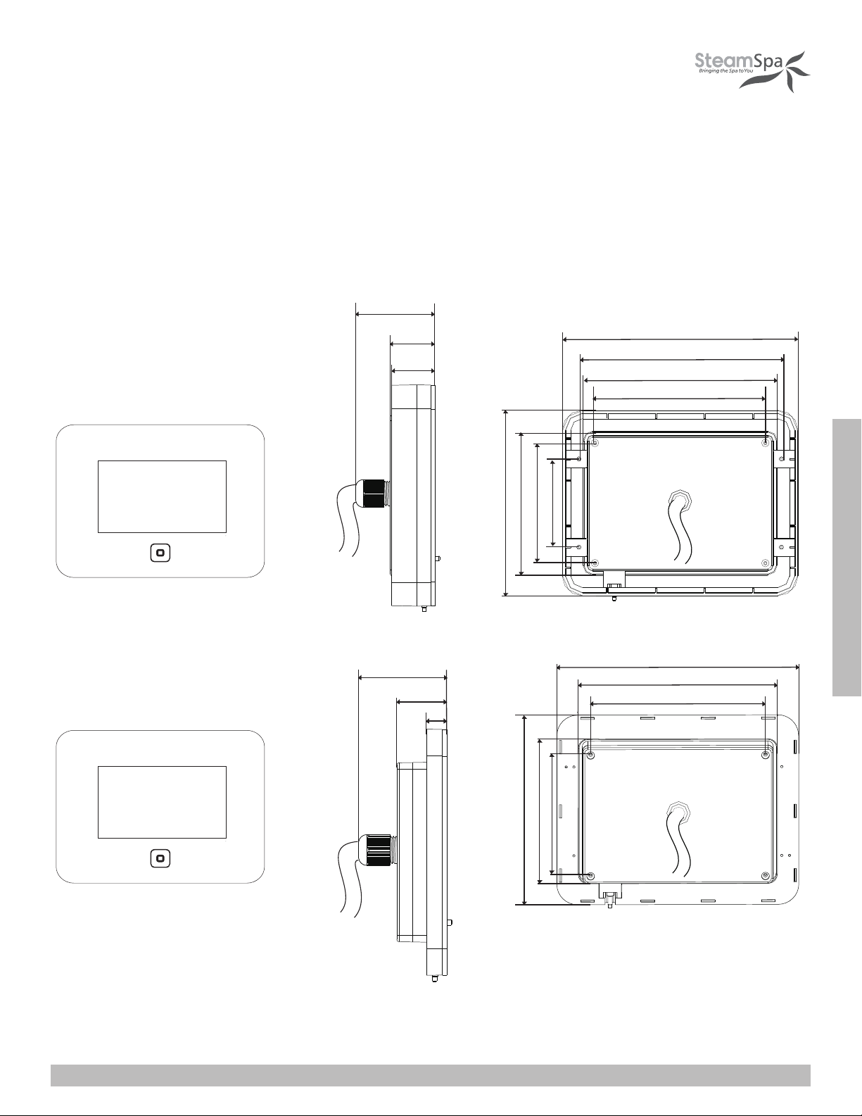
CONTROLLER SPECS
WITH EXTENSION RIM
1. 7
0
I NCH
0. 92 I NCH
0. 89 I NCH
5. 5 4INCH
4. 7 8INCH
4. 4 1INCH
4 I NCH
3.10 I NCH
3.20 I NCH
2.07 I NCH
4. 37 I NCH
NO EXTENSION RIM
1. 70 I NCH
0. 92 INCH
0.3 1 INCH
INSTALLATION & USER GUIDE
5. 5 4 I NCH
4. 4 1 I NCH
4 I NCH
3.20 I NCH
3.10 I NCH
4. 37 I NCH
Page 17
SteamSpa PHONE: 800-856-0172 FAX: 866-560-1060 http://steamspa.com [email protected]
Page 18
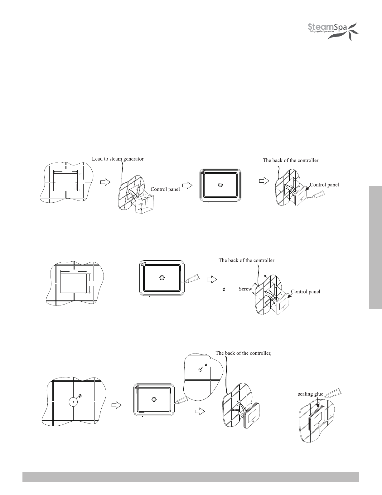
CONTROL PANEL INSTALLATION INSTRUCTIONS
Create the hole for control
box. Make it 47 to 50 inches
from the ground.
A. Recess mount onto the wall using the control box.
Place control box into the
hole. Insert screws to hold
control box in place.
Fix the control panel to the control
box. Add a bead of silicone around
the edge to seal.
Apply the double sided tape.
4.72”
3.5”
2.95”
Create the hole for control
box. Make it 47 to 50 inches
from the ground.
Create the hole for mounting
plate. Make it 47 to 50 inches
from the ground.
A. Recess mount onto the wall using the control box.
B. Recess mount with mounting plate.
Place control box into the
hole. Insert screws to hold
control box in place.
Fix the control panel to the control
box. Add a bead of silicone around
the edge to seal.
Fix the control panel to
the mounting plate.
Apply the double sided tape.
Apply the double sided tape to the
back. And add a bead of silicone
around the inner lip to seal.
4.5”
3.3”
4.72”
3.5”
2.95”
.15”
STEP ONE
Determine the installation location of the control panel. The master control panel is designed to be installed in the steam room only,
please install:
1. 4-5 feet from the ground.
2. Keep away from the steam head and do not expose under the direct spray of steam.
3. Install in the perpendicular wall.
4. The position of installation should facilitate easy operation and convenient wiring.
A. Recess mount onto the wall using the control box.
4.72”
3.5”
2.95”
Create the hole for control
box. Make it 47 to 50 inches
from the ground.
Place control box into the
hole. Insert screws to hold
control box in place.
B. Recess mount with mounting plate.
4.5”
3.3”
Create the hole for mounting
plate. Make it 47 to 50 inches
from the ground.
C. Using the double-sided adhesive.
Apply the double sided tape to the
back. And add a bead of silicone
around the inner lip to seal.
Apply the double sided tape.
Fix the control panel to the control
box. Add a bead of silicone around
the edge to seal.
.15”
.4”
Apply the sticker to the back
of the controller. And press
onto the wall.
INSTALLATION & USER GUIDE
Fix the control panel to
the mounting plate.
1.25”
Open a hole as shown above.
Make it 47 to 50 inches from
the ground.
SteamSpa PHONE: 800-856-0172 FAX: 866-560-1060 http://steamspa.com [email protected]
Apply the double sided tape to the
back. And add a bead of silicone
around the inner lip to seal.
Make sure to add the extension rim
behind the control panel’s edge.
Page 18
Page 19
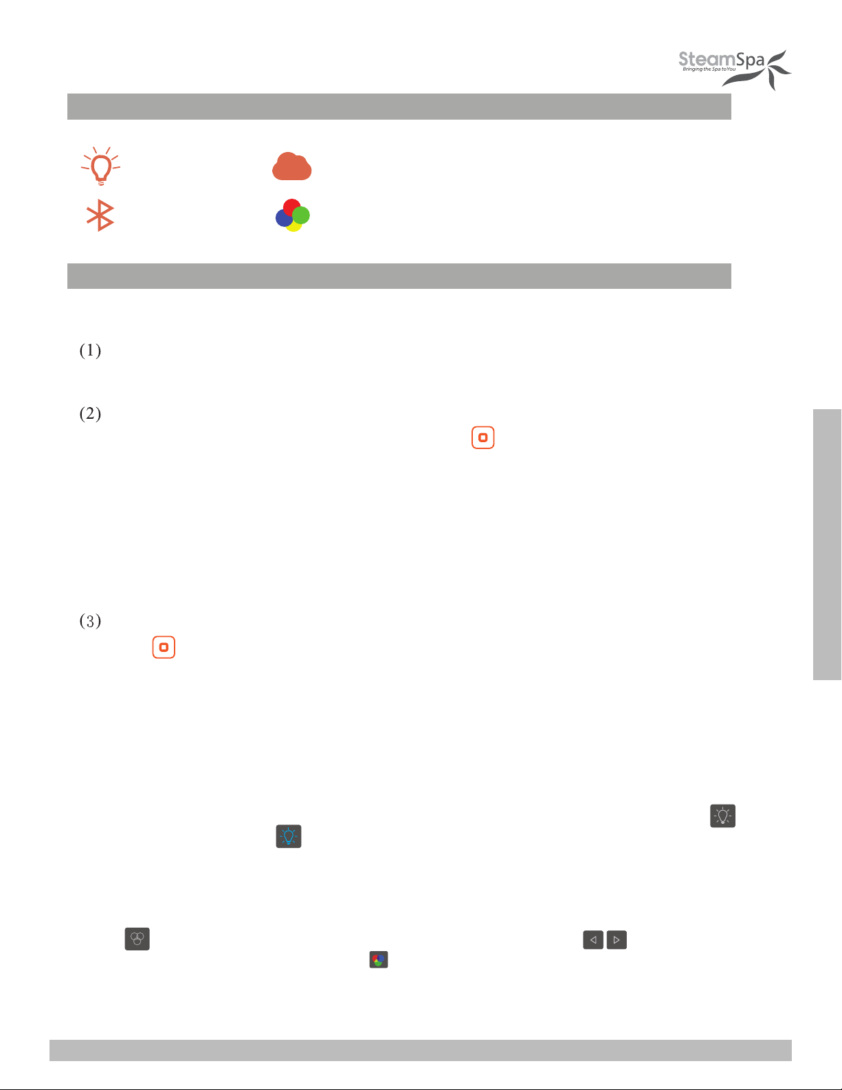
LED LIGHT
FUNCTIONS
STEAM
BLUETOOTH
OPERATIONAL APPROACH
1. START-UP/SWITCH OFF
POWER ON
The control panel will BEEP when it’s connected to a power source.
START-UP
When the system is under stand-by mode, press the key to start-up. The current
ambient temperature in the room and bluetooth music icon will be displayed on the
screen as shown in Figure 1. After the interface is fully displayed, press the function
key on the screen to unlock.
If a user has set the a scheduled start up function, when the secduled time arrives, the
system will start-up automatically and begin the process of producing steam.
CHROMA LIGHT
POWRE-OFF
Press the key to power down the control panel and enter standby mode. During this
mode the clock will be displayed on screen.
The system will power-off automatically when the pre-set time is reached. (The
system will be shut down after 2 minutes of the steam function closed.)
2. Control of White LED Light (If Equipped)
After power-on, the lighting section interface is shown in Figure 4 as follows: Press
to turn on the light ; Press to turn off the light.
3.Control of Color Changing Light (If Equipped)
When the system is power-on, enter in the lighting interface as shown in Figure 4:
Press key to turn on the Color-Changing light, and then press key to
change the color of the light. Press the key to turn off the Colored-light Function
after the color-changing light function is started.
INSTALLATION & USER GUIDE
Page 19
SteamSpa PHONE: 800-856-0172 FAX: 866-560-1060 http://steamspa.com [email protected]
Page 20
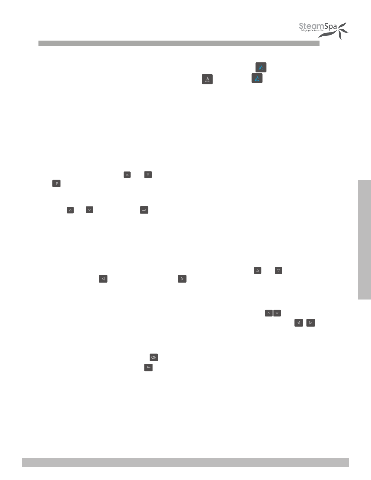
4.STEAM FUNCTION
Select the steam interface shown in Figure 1 after power-on: Press to start the
steam function; The steam key is shown as Figure ; Press the again to stop
the steam Function.
Steam temperature setting: Set temperature by pressing the key of "temperature+" or
"temperature-". Steam time Settings: Set to 5-60 minutes of steaming in 5 minute steps
by pressing the “time+” or “time-” keys.
Save user information: Through the user interface shown in Figure 5; select the user
bar to be used by pressing or key, then save your temperature and timing by pressing
the button.
To select your setting: Through the user interface shown in Figure 5: Select the setting to be used
with the or key, and press to select the saved user setting.
Scheduled start-up setting: Select the function bar of "Working Mode" shown in
Figure 6 on the setting interface, press OK key to enter the interface shown in Fig
ure 7
to set relative parameters.
① Time setting: Stop the cursor on the desired “Timing” by using the or key, set
hours by pressing key, and minutes by key. The parameters are set in loop
with 1 hour increments and a range of 0-23 hours; And a 10 minute increments and a
range of 0-50 minutes.
② Working mode: Move the cursor from Sunday to Monday bar with key, Then
select the function options of: off, one-time schedule, or repeat schedule with
key. If the one-time schedule mode is selected, the system will change the
setting to “off ”automatically after one-time scheduled cycle is complete.
③ Save information by pressing key and run as per the set parameters. Exit the
ting interface by pressing the key.
set
④ When system is running under the scheduled start-up mode, the temperature and
steamer working time set by user1 shall be taken as default. For example, if the
temperature is 110℉ and the working time is 30 minutes set by user1, then the
temperature shall be 110℉and the working time shall be 30 minutes under the
scheduled start-up mode. If the working time is adjusted after start-up, the scheduled
shut off time shall subject to the final set time.
INSTALLATION & USER GUIDE
SteamSpa PHONE: 800-856-0172 FAX: 866-560-1060 http://steamspa.com [email protected]
Page 20
Page 21
⑤ The system will automatically drain the generator 30 minutes after the last use for 5 minutes.
⑥ The system can be manually drained by holding the key after the system has been turned
on but steam generation has not started. Holding the key again or starting up the steam will
stop the drainage process. The drainage process will automatically stop when all water is gone.
5.CHANGE BETWEEN FAHRENHEIT & CELSIUS
Selection "F/C" function bar on the setting interface shown in fig.6 after power on,
press OK key to enter the interface shown in Figure 9. Press the "OK" key again to
shift between degrees Celsius and Fahrenheit.
6. RESTORE FACTORY SETTINGS FUNCTION
Select "Factory Setting" bar on the setting interface, and press the "OK" key shortly to
restore the factory parameter. The steam control temperature will return to 110℉ and
the steaming time to 30 minutes.
7.SET REAL-TIME CLOCK
Select the "Real Time" function through setting interface shown in Figure 6 after
power on, and press OK key to enter the interface shown in Figure 8. Move the cursor
to the parameters need to be set by pressing key, e.g.: Hour, minute, date,
month, year, displaying time or not after power off etc. Then adjust the parameters by
pressing key. The parameter of "week" will be calculated automatically by date
input system. Press the "OK" key to save the parameters set. Exit the interface by
pressing "ESC" key. The parameters won't be saved if the "OK" key is not pressed
before pressing "ESC" key.
INSTALLATION & USER GUIDE
Remarks: The real-time clock shall be recalibrated after they powe
system is more than one week.
r interruption of the
8.BLUETOOTH MUSIC FUNCTION
(1)Starting up Bluetooth: Connect your phone or other device to the control panel
after power on, select the interface as shown in Figure 3 and press key to power
on/off the bluetooth music function. The key state prompts under play mode are shown
as .
(2)Song switching: When the bluetooth music is playing: It can be switched to the
previous song by pressing key and the next song by pressing key.
(3)Volume adjustment: The music volume can be adjusted by pressing key
on the interface of bluetooth. The volume range (0-15) e.g. "10dB" may be shown on
the screen. ll be recalibrated after they power interruption of the syst
one week.
SteamSpa PHONE: 800-856-0172 FAX: 866-560-1060 http://steamspa.com [email protected]
em is more than
Page 21
Page 22
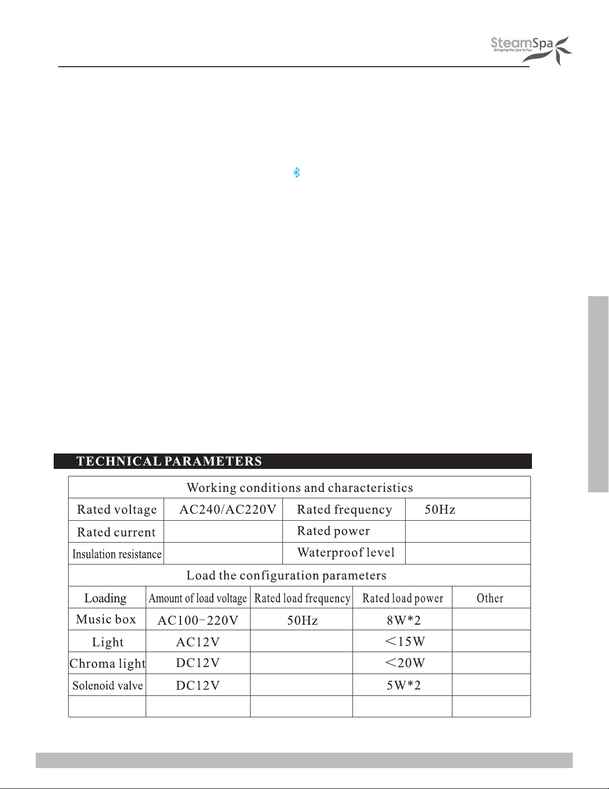
(4)The bluetooth connection will be cut off automatically10 seconds after system
power-off. When the cell phone is going to be restarted after 10 seconds, the bluetooth
shall be connected through the cell phone, then start the music player to play the
music. The bluetooth can be operated normally only after the synchronous success.
The bluetooth equipment was named as "sauna".
(5)The bluetooth status indicating icon will be flash on the bluetooth interface
when the bluetooth equipment is not connected, then, otherwise, it will stop flashing.
Page 22
INSTALLATION & USER GUIDE
SteamSpa PHONE: 800-856-0172 FAX: 866-560-1060 http://steamspa.com [email protected]
Page 23
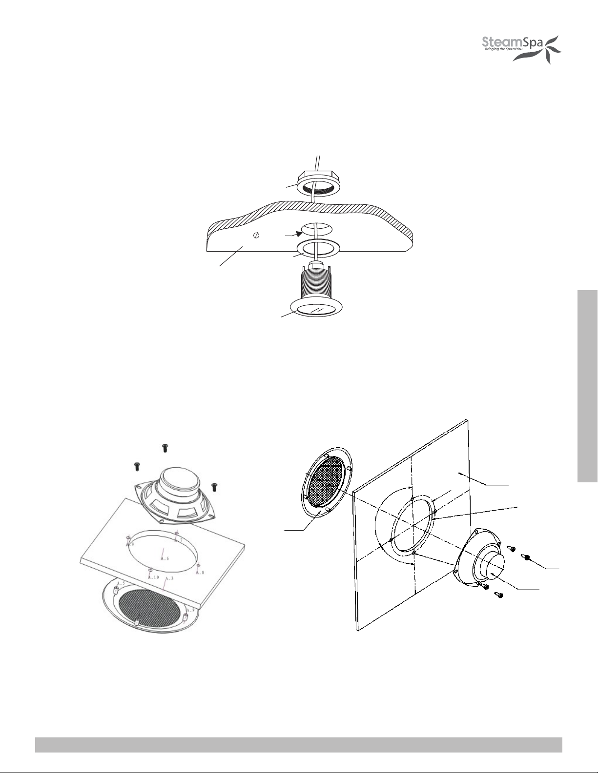
INSTALLING LIGHT
CAUTION! Installer must take some moisture proof measures in the process of installation. Electrophorus components cannot be
exposed to moisture, as it will cause damage to the light components causing a possible short circuit.
Tighten N ut
4 5m m
Rubber Gas ket
Ceiling of steam room
LED li ght
INSTALLING SPEAKERS
1. Chose a proper place on ceiling inside the steam room.
2. Open 4 holes with 5mm depth and 100mm diameter.
3. Fix the speaker and grill on the ceiling with the provided screws as pictured.
speaker
grill
90°
90°
INSTALLATION & USER GUIDE
ceiling
Ø4.58”
Ø3.9”
Ø4 to 7 holes
screw
speaker
SteamSpa PHONE: 800-856-0172 FAX: 866-560-1060 http://steamspa.com [email protected]
Page 23
Page 24
TESTING THE MACHINE
1. Make sure the power switch of the control panel is turned on (the control panel displays ---), and the water supply valve will
open.
2. Press the steam switch, , the control panel will display the temperature of the environment, the steam engine begins to input
water to start the steam function, and while opening the steam, press the button to open light function.
3. When there is steam output, press again, the steam will stop and the light will go off automatically.
4. Press the button to start the steam, the steam will come out of the steam generator in no more than 1-2 minute. As time goes
on, the temperature displayed in the control panel will rise with the temperature in the room before it stops and stays at the set
temperature.
5. Based on different requirements of the user for temperature and steam time, the control panel can adjust temperature and
steam time.
6. When the set steam time is due, the system will shut off the steam and light function automatically to stop water input and
steam production .
7. 30 minutes after the steam is shut off, the system will start drainage automatically for 7 minutes. After testing the machine and
it is working properly. Then the machine can be operated normally.
WARNING! Do not dismantle the safety pressure decrease valve arbitrarily.
IMPORTANT! Do not switch the water input pipe when the steam generator is working.
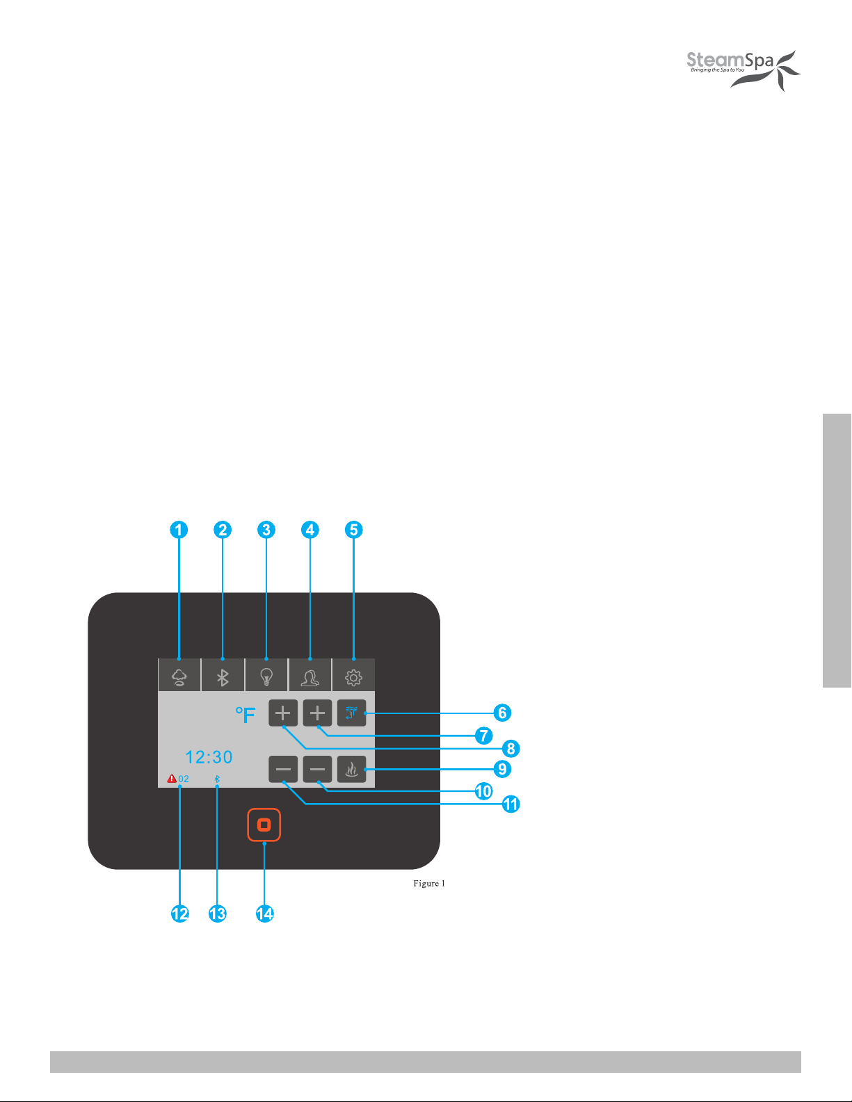
110
1. Steam Controls
2. Bluetooth Controls
3. Light Controls
4. User Presents
5. Settings
6. Steam Temp +
7. Steam Time +
8. Drain Water
9. Steam Temp -
10. Steam Time -
11. Start Steam Production
12. Error Codes
13. Bluetooth Icon
14. Standby Button
INSTALLATION & USER GUIDE
SteamSpa PHONE: 800-856-0172 FAX: 866-560-1060 http://steamspa.com [email protected]
Page 24
Page 25
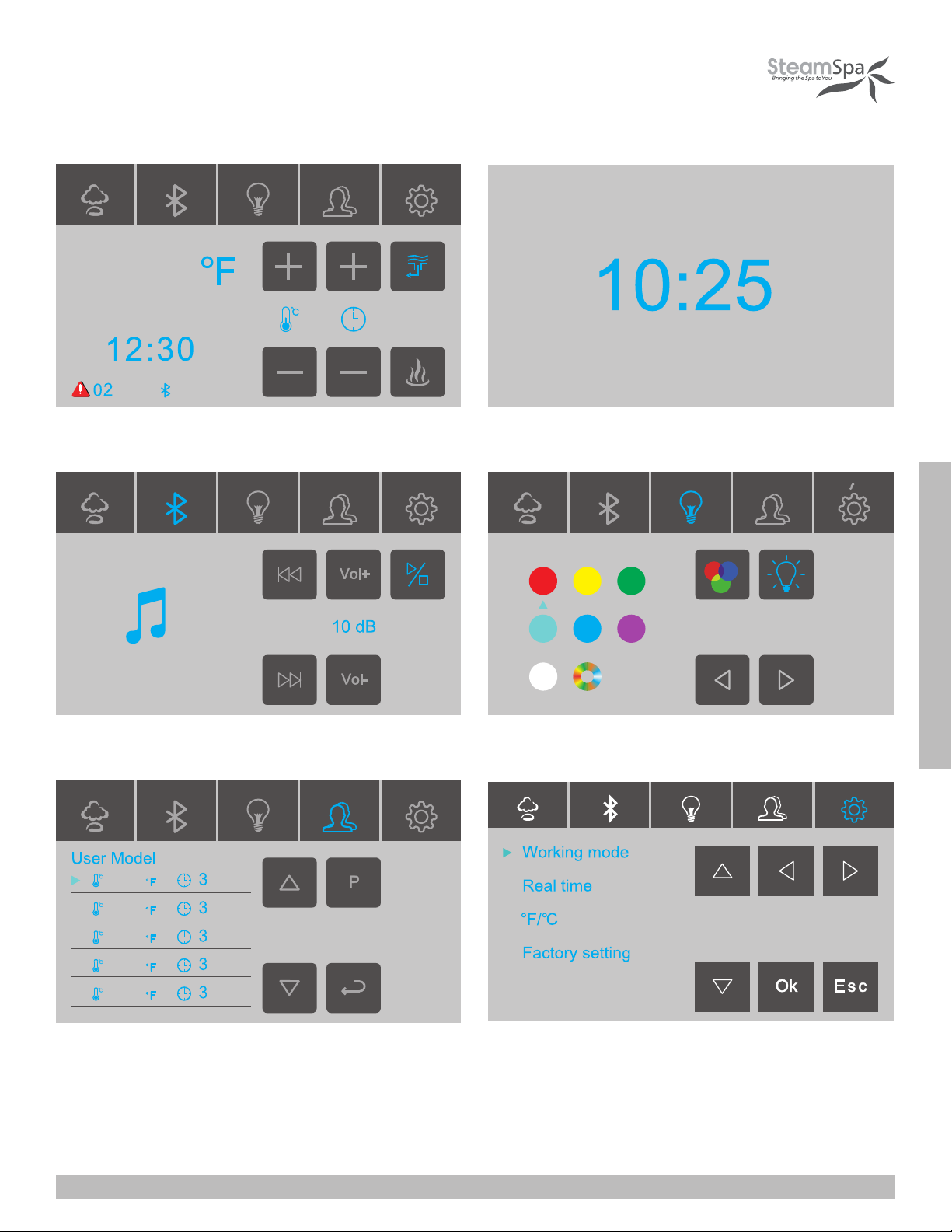
110
figure1 - main screen figure 2 - clock screen
figure 3 - bluetooth screen figure 3 - light screen
INSTALLATION & USER GUIDE
110 0
110 0
110 0
110 0
110 0
Min
Min
Min
Min
Min
figure 4 - user presents figure 5 - se�ngs
SteamSpa PHONE: 800-856-0172 FAX: 866-560-1060 http://steamspa.com [email protected]
Page 25
Page 26
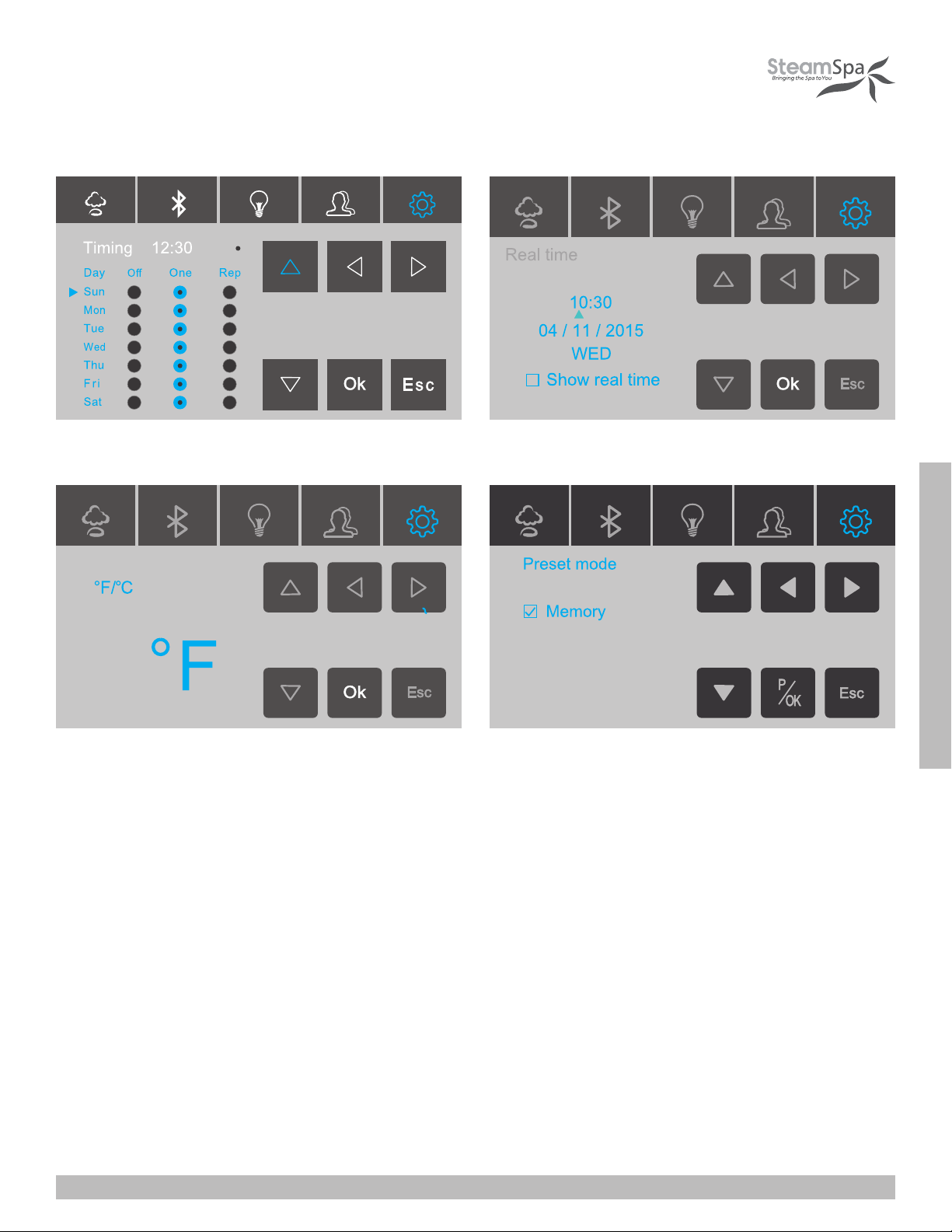
figure 8 - clock se�ngs
figure 10 - presents mode
INSTALLATION & USER GUIDE
SteamSpa PHONE: 800-856-0172 FAX: 866-560-1060 http://steamspa.com [email protected]
Page 26
Page 27
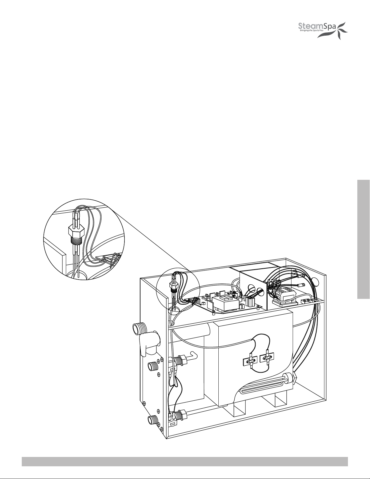
STEAM GENERATOR MAINTENANCE
IMPORTANT! The steam generator automatically performs a water discharge operation after each use.
1. Wait for the completion of automatic water discharge after each time using the steam generator to make sure the water in the
tank is discharged completely before cutting off power supply.
2. There should not be any leakage or damage among the steam generator, steam nozzle, components and pipes. They should
be checked and repaired annually.
3. Clean the water supply pipes of the steam generator once a year.
4. Check all the pipe connections, to ensure wether they are tight and not damaged due to overheat.
5. It is recommended that the water sensor prong gets clean once every six month.
1. Remove the casing of the generator.
2. Locate the water sensor.
3. Label each electrical connections then carefully remove all connections.
4. With a wrench or a 32mm ratchet socket carefully unscrew the water senor.
5. Thoroughly clean any residue buildup accumulated on the prong.
Page 27
INSTALLATION & USER GUIDE
SteamSpa PHONE: 800-856-0172 FAX: 866-560-1060 http://steamspa.com [email protected]
Page 28
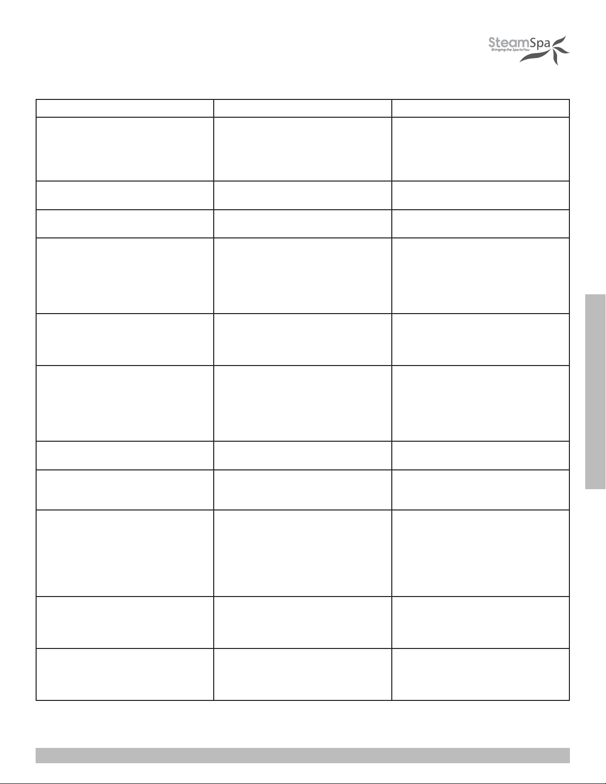
TROUBLESHOOTING GENERATOR
PROBLEM POSSIBLE CAUSES SOLUTIONS
The machine does not start when
powered
Breakers are tripping
When the machine is started, hot water
comes out with little or no steam
The display screen on the control panel
does not display anything
Water leakage
No steam when starting the machine
The steam does not come out, the water
sounds in the machine
Light doesn’t turn on
1. Burned out fused
2. The electrical wiring became loose
3. Control panel connection loose
1. Check gauge size
2. Damaged heating element
1. Check inlet valve
2. Check cable pins
1. The control panel wire is not
connected properly
2. Trouble with generator
motherboard
1. The water pipe connector becomes
loose or pipe is broken.
2. Water leakage in the water input
valve or the water drainage valve
1. No electricity
2. No water
3. The set temperature is too low
4. Wiring connection problem
1. Check heating element 1. Clean or replace heating elements
1. Bad LED light bulb
2. Wiring connection improperly
connected or light cable damage
1. Replace fuse (0.8A/240V)
2. Cut power Supply and reconnect
wiring
3. Reconnect control panel and reset
4. Controller (turn off and on)
1. Replace wire with correct gauge
2. Replace heating element
1. Clean or replace valve
2. Clean or replace pins
1. Check whether the connection plug
between the control panel and the
generator has become loose, and
whether the power circuitry has
good contact
2. Replace the motherboard
1. Tighten the loose connection or
change the broken pipe
2. Change the water input valve or the
water drainage valve
1. Check the power supply and
connections
2. Check the water input pipe and water
input valve
3. Reset the temperature
4. Check wiring connection and tighten
INSTALLATION & USER GUIDE
1. Change LED light bulb
2. Tighten connection or replace light
cable
1. The water sensor cable is loose or
Cold water is coming from the steam
head
05 Error Code 1. Water inlet problem
SteamSpa PHONE: 800-856-0172 FAX: 866-560-1060 http://steamspa.com [email protected]
water level sensor is defected
2. Check cable pins
3. Check inlet water valve
1. Make sure that the water level
cable isn’t loose if the cable is well
connected replace the water sensor
2. Replace cables
3. Clean or replace inlet valve
1. Check water supply for proper flow
2. Check inlet valve for blackage. It
many need cleaning or replacement.
Page 28
Page 29
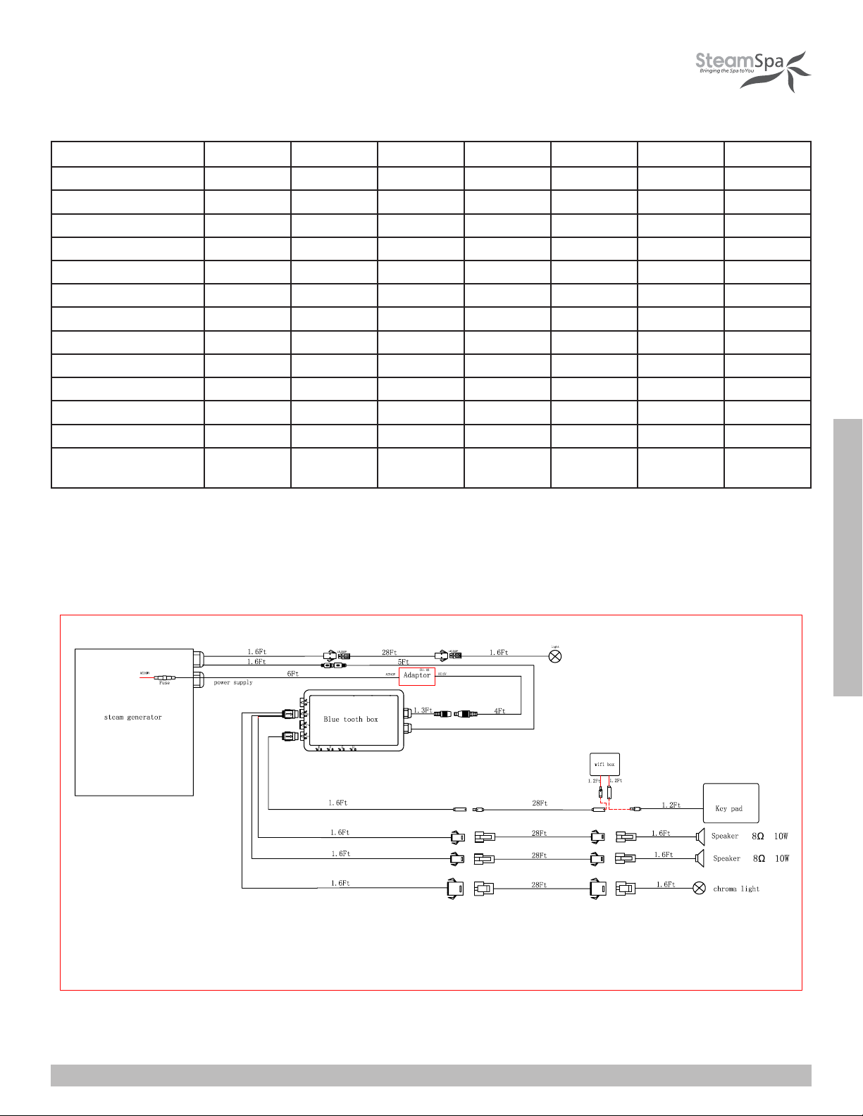
TECHNICAL PARAMETERS
Type
Power (KW) 4.5 6 7.5 9 10.5 12 15
Voltage (V) 240 240 240 240 240 240 240
Current (A) 19 25 32 38 44 50 63
Errors Range +10% +10% +10% +10% +10% +10% +10%
Anti-Static Constant >1500V >1500V >1500V >1500V >1500V >1500V >1500V
Insulation Resistance >20M Ω >20M Ω >20M Ω >20M Ω >20M Ω >20M Ω >20M Ω
Head Lamp ~12V/3W ~12V/3W ~12V/3W ~12V/3W ~12V/3W ~12V/3W ~12V/3W
Time Set Range (min) 1-60 1-60 1-60 1-60 1-60 1-60 1-60
Steam Press (psi) 3 4 4 4 5 5 5
Steam Vol. (cu. in./min) 9 11 13 16 19 21 25
Steam Spray Time (sec) 100-180 180-240 150-210 120-180 170-230 150-160 120-150
Water Vol. (cu. in.) 80 160 160 160 330 330 330
Applicable Space of the
Room (cu. ft.)
IMPORTANT! The list above is for reference only. Actual checking and repairing should be based on national and local codes, ask
professional service personnel to operate.
IMPORTANT! The parameter listed above will vary by geographical location and environment. Please consult a qualified designer
and architect for more detailed use.
4.5KW 6KW 7.5KW 9KW 10.5KW 12KW 15KW
90 150 225 300 400 450 500
Page 29
INSTALLATION & USER GUIDE
SteamSpa PHONE: 800-856-0172 FAX: 866-560-1060 http://steamspa.com [email protected]
Page 30

STEAM SPA TROUBLE SHOOTING
Generator Maintenance and Service should be completed by Licensed Plumber or Electrician
*Turn Off Electrical Breaker and Water Supply Before Any Work On Electrical Connection is attempted*
UNIT LEAKING WATER OUT OF THE STEAM OUTLET:
• PSI TO UNIT GREATER THAN 15-20PSI: Confirm that the PSI going to the unit is regulated between 15-20 PSI (Most
House Lines Run Off approx. 50-100, (a Pressure Regulating Valve may be required).
• WATER SENSOR IS DEFECTIVE: (New Generator/Elements): Remove heating elements and check for corrosion/burn out
of element.
• SEDIMENT STUCK IN LINE: Remove threaded line to water intake. Remove Screen before the solenoid valve and check
for sediments. If sediment found look into adding or replacing the filter and removing sediment.
MY CONTROL IS NOT TURNING ON:
(To test, plug control panel directly into the Generator via the shorter 1 ft. cable)***Turn Off Breaker Before Any Work On Electrical
Connection is attempted***
• BREAKER IS NOT TURNED ON: Have the customer check if the breaker has been turned on for the unit.
• LOOSE CONTROL PANEL CABLE CONNECTION: Check to see if “XYZ” arrow on the connection are lined up and
plugged into each other completely. The wires need to snap completely in, to where there is no space between both sides
of the connector
• WIRE GAUGE FOR ELECTRICAL CONNECTION INCORRECT: Check the gauge of wire installed, and compare to the
“Ampere Meter” chart on pg. 13 of the manual, to ensure correct gauge wire is being used.
• AMPERAGE NOT SUFFICIENT: Check breaker size against the “Ampere Meter” chart on pg. 13 of the manual. If breaker
is not sufficient, the breaker will need to be changed.
• VOLTAGE NOT SUFFICIENT: Ensure that the generator is connected 240v electrical supply.
• DAMAGED 1FT. CONTROL CABLE: Have customer check the pins at the male connection coming from the back of the
generator. If pins look to be okay, remove lid to see if connection made at terminal block is loose. If so press connection in
completely.
• DAMAGED CONTROLLER EXTENSION CABLE: Look at the male and female end of the 20ft extension. Check if there is
visible damage to the pins and connection, or if any pins are missing from the male end of the cable.
• LOOSE CONNECTION AT TERMINAL BLOCK: Make sure all connection made at the terminal block are inserted and
tightened securely.
• BROKEN FUSE HOLDER: Unscrew top panel and look at fuse connections. If any damage seen to the fuse holder or
connection.
• FUSE HAS BURNT OUT: Unscrew fuses (2 black rubber screws located on the exterior of the generator in-between the
electrical connection and control panel connection cable). Look to see if fuse wire is broken or dark residue on inside of
fuse.
• MOTHERBOARD MALFUNTION: please contact Technical Support to request new Motherboard.
INSTALLATION & USER GUIDE
CONTROL PANEL READING E1 (CONTROL CONNECTION) ERROR:
• CONTROL CABLE CONNECTION LOOSE: Confirm that control cable connections are tightly made by pressing together
firmly at xyz connections.
• CONTROL CABLE PINS BROKEN: Confirm that the cable connections are intact and no pins are missing from the
generator to extension connection or the extension to control panel extension.
• LOOSE SHORT CONTROL CABLE: Remove the top of the unit. Then look to see where the large grey wire runs to the
mother board. Press down on white connection and snap into place.
• DAMAGE TO CONTROL PANEL CONNECTIONS: Inspect the grey cable that runs from the motherboard to the control
panel inspecting the 3 Cables. (1 ft. Generator Cable, 20 ft. Cable Extension, and the grey Control Panel Cable) , looking
for kinks in the line where wiring could have broken.
• LOOSE RELAY CONNECTION: Check to see if all connections are completely secured on the motherboard and connection
points. If any are loose, secure connection.
Page 30
SteamSpa PHONE: 800-856-0172 FAX: 866-560-1060 http://steamspa.com [email protected]
Page 31

STEAM SPA TROUBLE SHOOTING
CONTROL PANEL READING EO (WATER LEVEL) ERROR:
• WATER PRESSURE NOT SET CORRECTLY: Confirm that the PSI going to the unit is regulated between 15-20 PSI (Most
Homes can have approx. 50-100psi).
• FLOW TO UNIT NOT REDUCED: Reduce flow of water by closing shut-off valve on water intake line to 20% open and
80% closed.
• WATER LEVEL SENSOR CONNECTION IS LOOSE: Remove top panel of generator and check to see if there are loose
connections on the water level sensor by removing rubber cover. If so snap into place and replace rubber cover.
• WATER LEVEL SENSOR HAS SEDIMENT OR CALCIUM BUILDUP: Remove Water level Sensor and check for corrosion/
buildup. If there is build-up on the sensor prongs, soak for approx. 15-20 min in vinegar then wipe off the residue
buildup. If the sensor is corroded, contact Technical Support to request a new Water Level Sensor.
• SEDIMENT STUCK IN LINE: Remove threaded line to water intake connection. Check inside of the inlet connection
for sediments. If sediment found look into adding or replacing the filter and removing sediment from the inside of the
connection. (Water inlet valve may need to be removed from generator for service)
GENERATOR TRIPS BREAKER:
• INSUFFICIENT VOLTAGE: Confirm that Voltage to the unit is 208v/220v/240v.
• INSUFFICIENT AMPERAGE: Confirm that Amperage to the unit sufficient (max output + 20%)
• IMPROPER GAUGE WIRE: Confirm gauge of wire for the electrical connection to the unit. If it is larger than the required
size decrease until you are at the recommended gauge or lower.
CONTROL PANEL ON WITH NO FUNCTION:
• CONTROL CABLE PINS BROKEN: Confirm that the cable connections are intact and no pins are missing from the
generator to extension connection or the extension to control panel extension.
• CONTROL CABLE CONNECTION IS LOOSE: Confirm that control cable connections are tightly made by pressing together
firmly at xyz connections.
• LOOSE RELAY CONNECTION: Check to see if all connections are completely secured on the motherboard and connection
points. If any are loose, secure connection.
• DEFECTIVE MOTHERBOARD: Faulty motherboard. Faulty motherboard; please contact Technical Support to request new
Motherboard.
DECREASED STEAM PRODUCTION/ NO STEAM PRODUCTION :
• HEATING ELEMENTS ARE CORRODED/DAMAGED: Remove top, side, and small back access panels. Disconnect
leads from the heating elements and remove the elements from the generator, and inspect the elements for corrosion or
damage.
• HEATING ELEMENTS HAVE CALCIUM OR SEDIMENT BUIDLUP: Remove top, side, and small back access panels.
Disconnect leads from the heating elements and remove the elements from the generator, and inspect for build-up. Soak
for approx. 15-20 min in vinegar then wipe off the residue buildup. (Buildup on elements a sign that the filter may need
to be changed or added)
• FILTRATION TO THE UNIT HAS NOT BEEN CHANGED: Customer has not changed the filter to their unit in the
recommended time frame (provided within our warranty policy). Remember that heating elements do vary depending on
the wattage of the unit.
• LOOSE WIRE CONNECTION TO HEATING ELEMENT: Remove the panel underneath the electrical connection and the
control panel power cable. Look to see that connection made at element are both properly and securely made.
INSTALLATION & USER GUIDE
SteamSpa PHONE: 800-856-0172 FAX: 866-560-1060 http://steamspa.com [email protected]
Page 31
Page 32

STEAM BATH GENERATOR USER GUIDE
W
H
I
S
P
E
R
Q
U
I
E
T
B
U
I
L
T
-
I
N
A
U
T
O
D
R
A
I
N
C
O
N
T
I
N
U
O
U
S
S
T
E
A
M
Q
U
I
C
K
S
T
A
R
T
Steam Spa PHONE: 800-856-0172 FAX: 866-560-1060 http://steamspa.com [email protected]
 Loading...