

Steam Planet WS-112 Installation & Operation Manual
Rev 3/2012
WS-112
Installation & Operations Manual
Note: You must read all installation & operation instructions prior to assembly and use of this unit.
1 | P a g e

Rev 3/2012
Part 1
Installation Manual …………………………………………… 3 – 15
Cleaning & Maintenance …………………………………………… 16
Part 2
S6 Operations Manual
Table of Contents
a. Safety Notes …………………………………………… 17
b. Parameter for Steam Cabin …………………………. 17
c. Control Box Electrical Diagram ………………… 18
d. S6 Wiring Diagram ………………………..………… 19
e. Control Diagram ……..…………………………… 20-21
f. Operation Instructions ……..…………………………… 22-25
g. Wireless FM Transmitter ………………………… 26
h. Steam Generator Cleaning ………………………… 27
i. Troubleshooting …………………………………………… 27-28
NOTICE TO INSTALLERS (if applicable)
THE FLEXIBLE DRAIN HOSE THAT IS INCLUDED WITH THIS UNIT IS FOR INSTALLATION
INTO AN OPEN FLOOR DRAIN ONLY. SUBSTITUTING THE EXISTING DRAIN SHOE FOR A
DIFFERENT ONE WILL NOT VOID THE WARRANTY AS LONG AS THERE NO DAMAGE OR
EVIDENCE OF MISUSE TO THE BASE
Note: Within the Warranty period, please don’t take off the decals from the computer
control boxes and the steam generator without manufacturer’s permission. Please do not
maintain or change the circuit by yourself. Usually most of the problems could be
troubleshoot over the phone. When calling for service questions, please provide your model
number, serial number, Purchase Order, and type of problem you are having.
2 | P a g e

Rev 3/2012
Part 1
Electric Parameter
Size
Model
System
Voltage
Power
Frequency
Length
Width
Height
WS112(32)
Steam System
220V
3KW
60-50Hz
59 Inch
32 Inch
84.5 Inch
WS112(36)
Steam System
200V
3KW
60-50Hz
59 Inch
36 Inch
84.5 Inch
WS112(40)
Steam System
200V
3KW
60-50Hz
59Inch
40 Inch
84.5 Inch
3 | P a g e

Rev 3/2012
4 | P a g e

Rev 3/2012
Tools required for installation:
Leveler
Screw driver
Silicone
Spanner
Electric Drill
Triangle Ruler
Hammer
5 | P a g e
Rev 3/2012
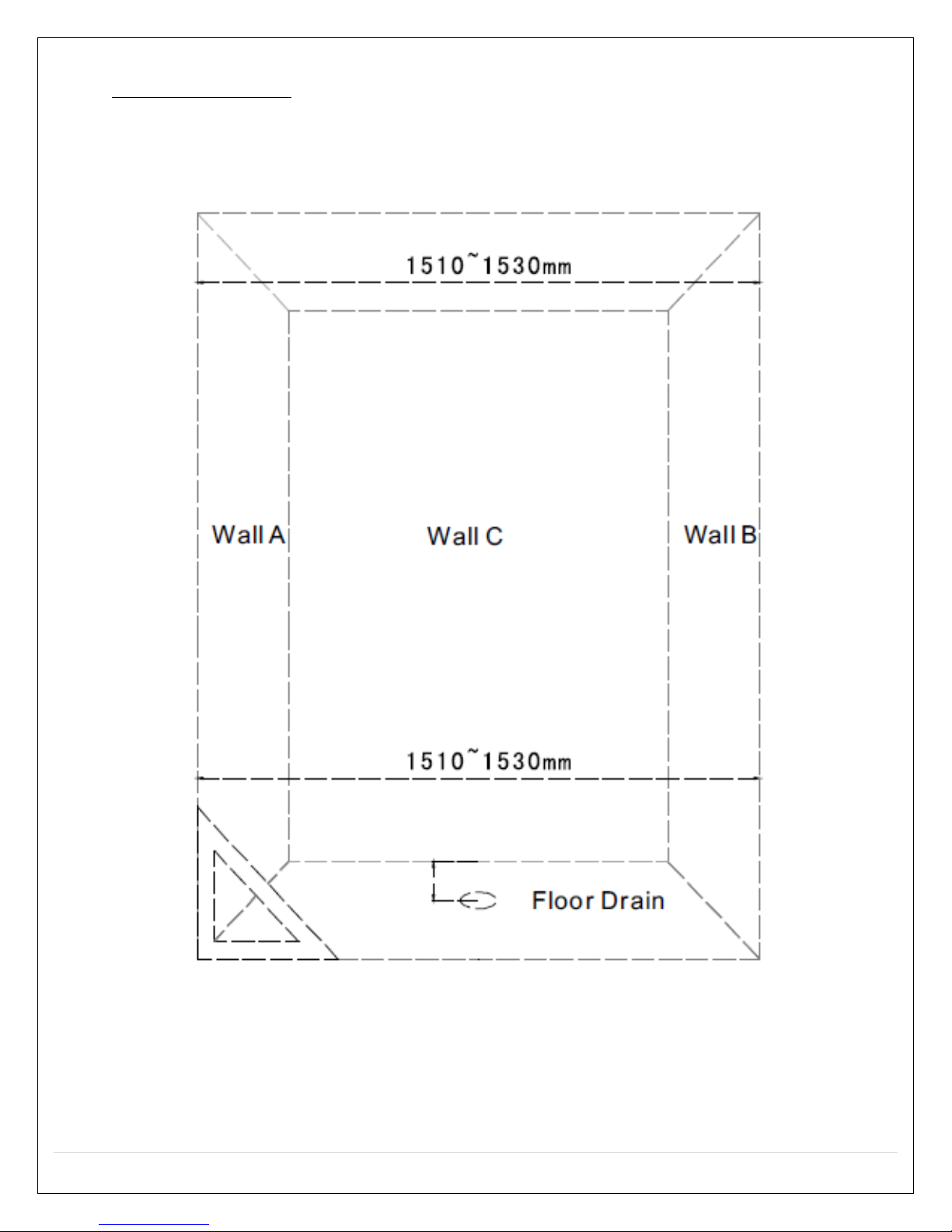
Place of Installation
The distance between Wall A and Wall B should be within 1510 to 1530mm
(59.5 to 60.3 inches). The distance between Wall A and Wall B bottom to
2000mm (78.75inches) height should be less than 10mm (.4inches).
1510mm to 1530mm = 59.5” to 60.3”
6 | P a g e
Rev 3/2012
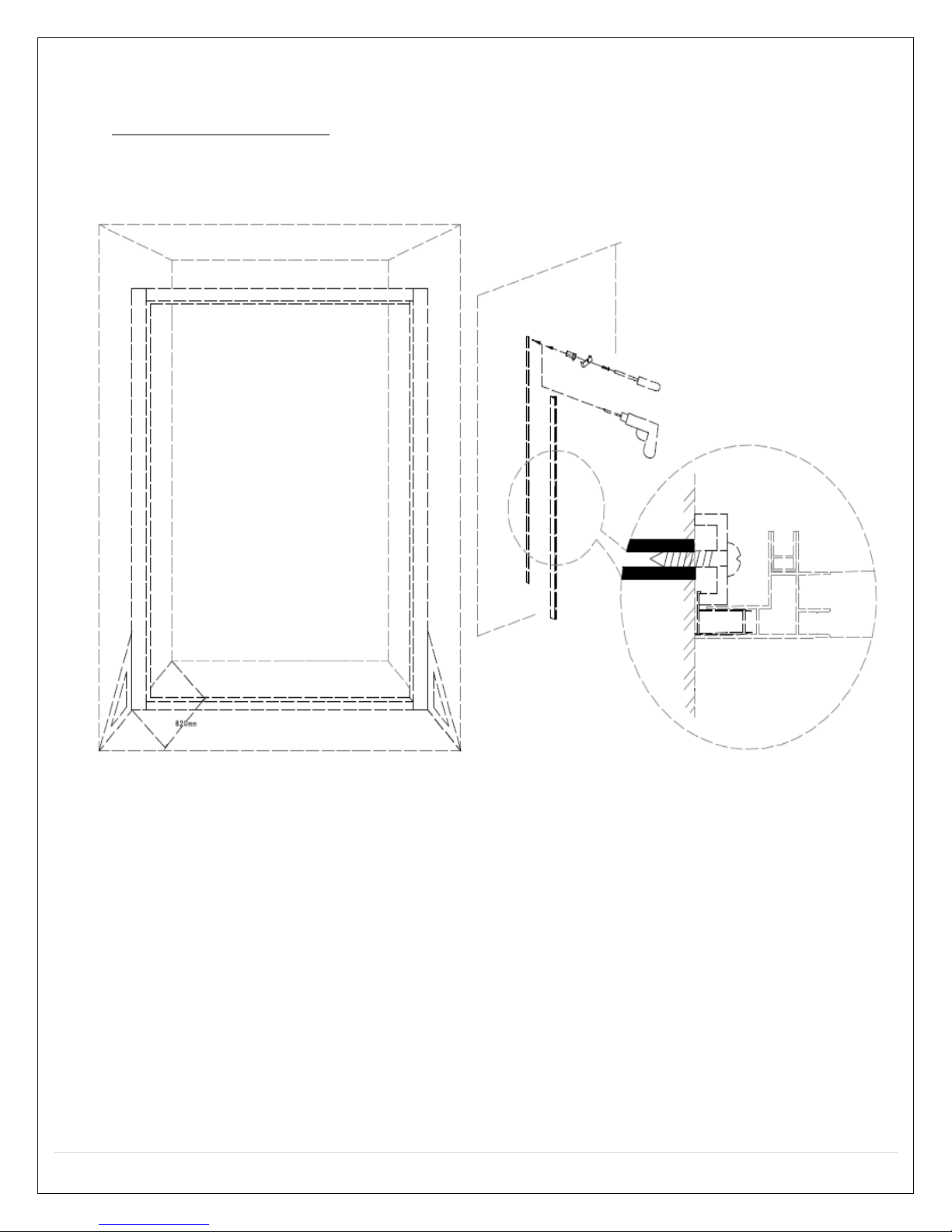
Door Frame Installation
Drill holes on Wall A and B, use the inflating nut.
i. Note: For California: Get the door frame fixed to wall with tapping screws
and blocks
820mm = 32.3in
7 | P a g e
Rev 3/2012
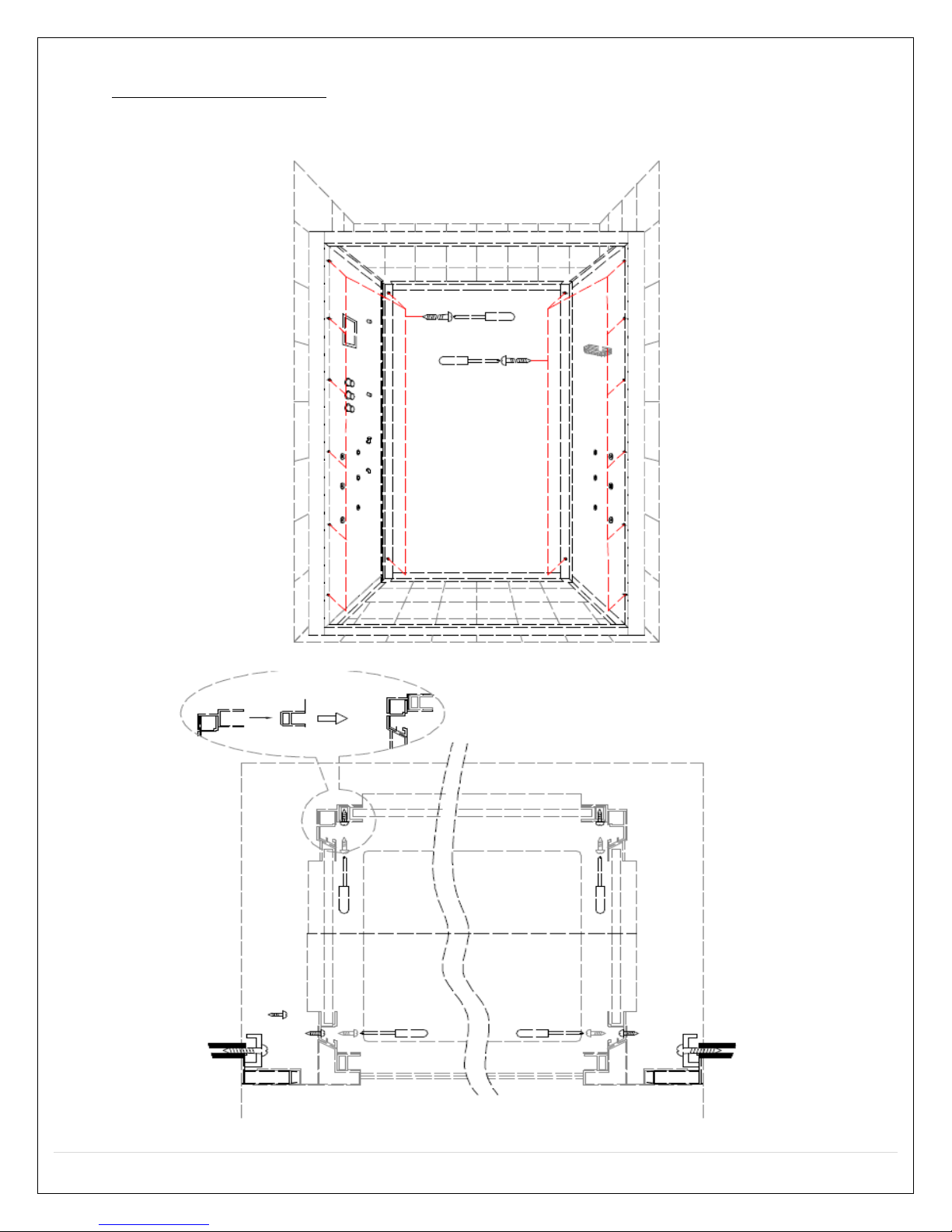
Installing Shower Walls
Get Power supply and water supply connected
Attach all the panels with taping screws
8 | P a g e
Rev 3/2012
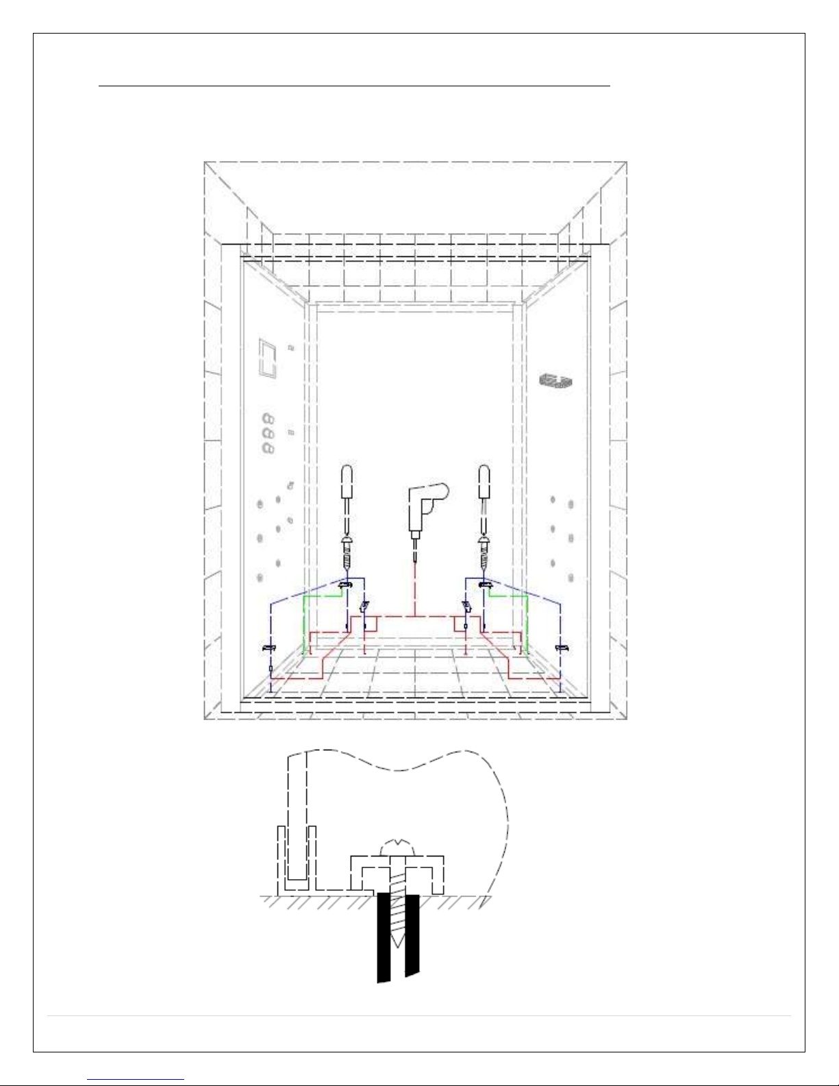
Attach All Side Panels to the Floor (not with custom stone base)
Drill hose on the floor (or optional acrylic base)
Attach all sides with tapping screws and blocks
9 | P a g e
 Loading...