

Steam Planet M-A020 Installation & Operation Manual
REV 03/2012
Installation & Operation Manual for M-A020
1 | P a g e

REV 03/2012
Table of Contents
Specification Page …………………………………………… 3-4
Unit Parameters …………………………………………… 5
Drain Disclosure …………………………………………… 6
Rough-In Diagrams …………………………………………… 6-7
Tools Need for Installation …………………………………………… 8
Feature Locations …………………………………………… 9
Installation Manual …………………………………………… 10-18
Troubleshooting …………………………………………… 19
Replacing Door Rollers …………………………………… 20
Replacing Curved Glass …………………………………… 21-22
Cleaning & Maintenance …………………………………………… 23
Shower Control Panel …………………………………………… 24
Remote Control …………………………………………… 25
Function Instructions …………………………………………… 26-27
Technical Data ……………………………...…………… 28
Thank you for selecting Steam Planet Corp Computerized Steam Room, we hope that our
exquisite design will meet your life’s needs; it’s our honor to promote your health and
longevity with comfortable enjoyment.
In order to operate and use the product well, please read carefully and follow all
instructions provided in this User’s Manual. We are dedicated to providing satisfied service
for you.
Our company reserves the right to change the Manual. The manual takes effect since the
date it is published. This manual shall prevail if there’s any difference between this and
previous documents and manuals.
Thanks for your support.
2 | P a g e
REV 03/2012
TECHNICAL INFORMATION
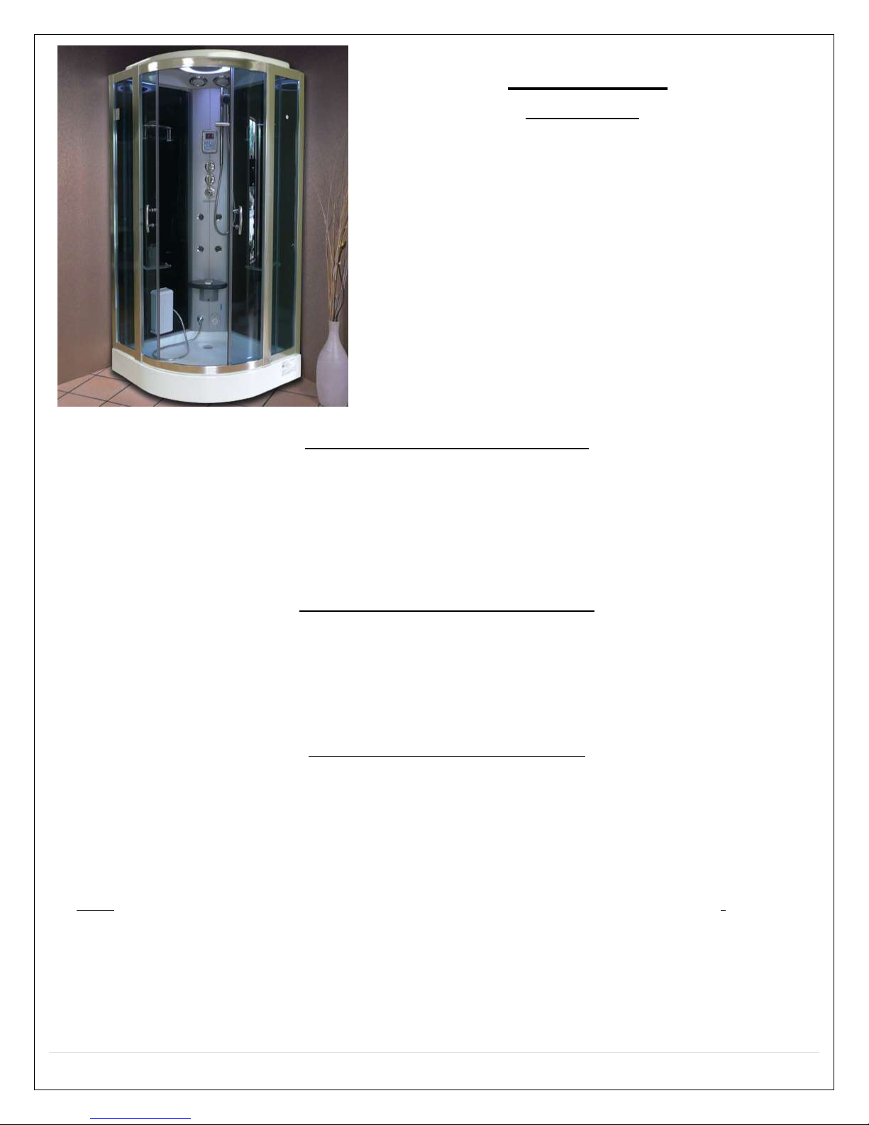
FEATURES
M-A020
Factory tested
Corner Unit
Polished Finish
Phone
Auxiliary RCA input
Steam Aromatherapy Cup
Towel bar & Accessory rack
Blue tinted doors and solid
black walls
Foot Massage
Body Massage Jets
Rainfall Shower Head
Mood light
Sliding Doors
Hand-held Shower w/
Height-Adjustable Bracket
Adjustable Time & Steam
Temperature Settings
Control Panel with Remote
Circulation Fan
Tempered Glass
2.5kW Self-Cleaning Steam
Generator
Folding Seat
Pressure Balance Valve
(optional extra)
FM Transmitter (optional
extra)
Materials: Acrylic, Aluminum, Tempered Glass
Power Supply: 220V
Steam Ready: 2-5 MIN
Dimensions: 37 x 37 x 87 IN
1 dedicated 12-2 line for steam (line 1, line 2, and ground)
220 volt, 20 amp GFCI breaker
There is a length of wire from the control box supplied to connect to power source.
The unit is equipped with hot and cold, metal braided ½ inch 3 foot long water supply hose with ½
national pipe thread.
Need to install hot and cold shutoffs with ½ -male national pipe thread (not included).
Supply hoses are to connect from the faucet manifold on the unit to the shutoff valves.
All water jet features are pre plumbed with reinforced braided flexible supply hose
All fixtures and fittings must be checked for tightness as they may have been loosened during transport.
Access panel area recommended.
Note: The flexible drain hose included with this unit is for installation into a floor drain only. Substituting
the existing drain setup for a setup of the installers’ choice will not void the warranty of the unit as long
as there is no evidence of misuse or damage to the base. If the substitute drain system is used, a 3/8 in
stub must be added to the main shower drain line to connect the steam generator’s automatic flushing
drainage hose.
Please call the manufactured for updated drain info 1-866-STEAM-61
ELECTRICAL INFORMATION
PLUMBING REQUIRMENTS
3 | P a g e
REV 03/2012
GENERAL INFORMATION
Units come broken down in panels and are assembled with screws, nuts and bolts on site. All seams and
joints are to be caulked with 100% silicone at room temperature (no latex caulking)
Note: It is advised to have base onsite before preparing drain location. All shower bases need to be leveled
in its final resting position, mark the placement, then pull base out and begin assembly.
Access panel near controls panel and jets recommended.
Manufacturer reserves the right to change specs or features at anytime. Please check to confirm
details. 1-866-783-2661
4 | P a g e
REV 03/2012
Unit Parameters
5 | P a g e

REV 03/2012
System
Electric Data
Size (mm/inch)
M-A020
Voltage
Power
Frequency
Length
Width
Height
220V
3.5kW
50~60Hz
950/37
950/37
220/86
6 | P a g e
REV 03/2012
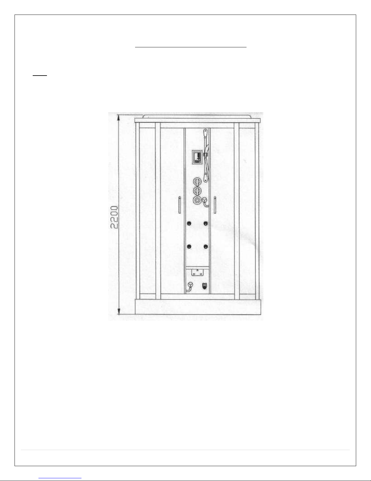
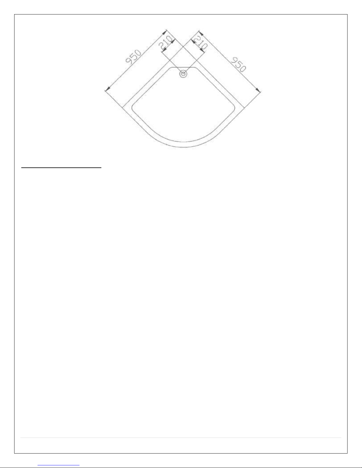
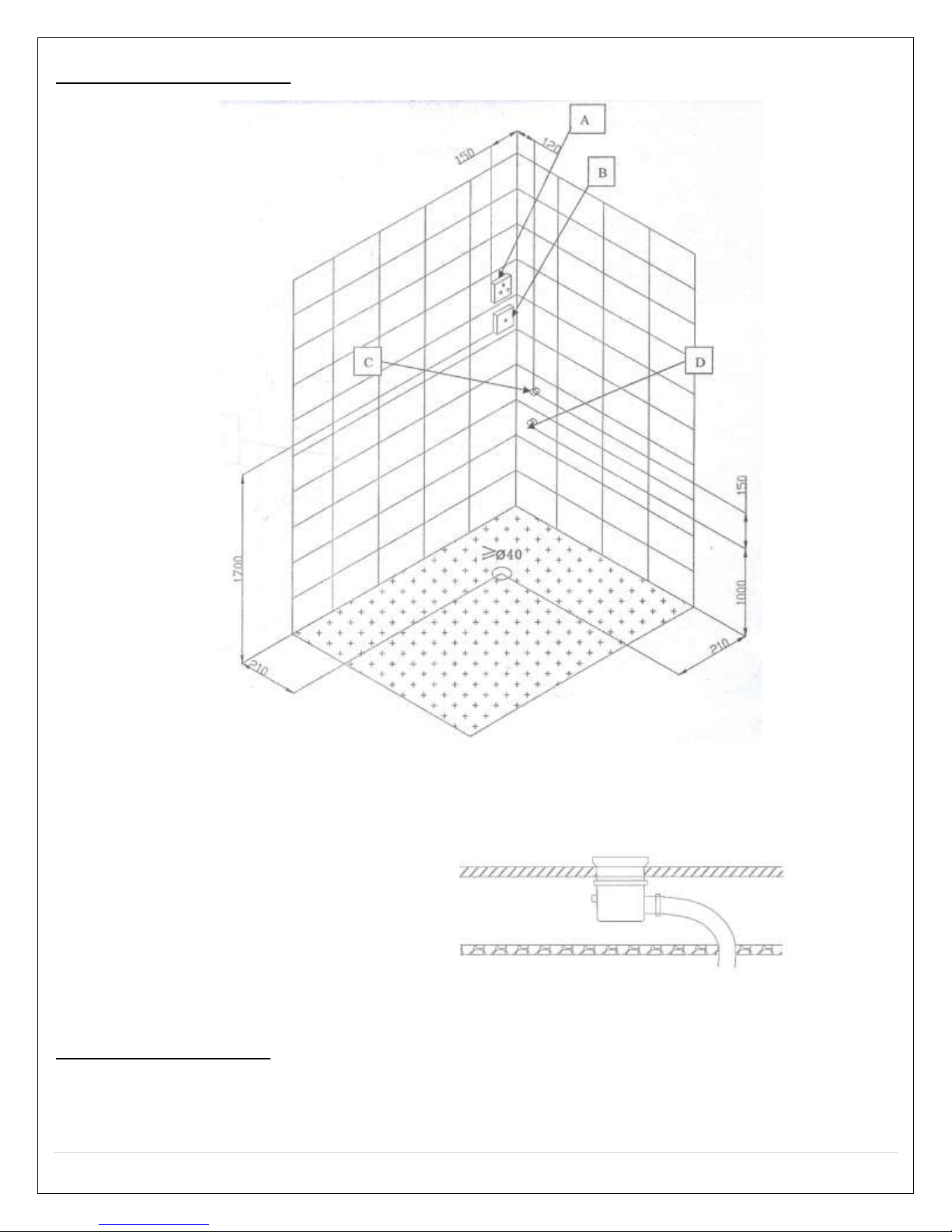
Rough-In Diagram
Diagram Key:
a. Hot Water Inlet
b. Cold Water Inlet
c. Phone Hook-up
d. Power Hook-up
e. Ø40 Drain Hole
Drain Disclosure
NOTE: a flexible drain hose is provided with the unit. We strongly recommend taking off the flex
drain hose and hard pipe the unit into existing drain. This will not void the warranty. Call 866STEAM-61 for any questions.
7 | P a g e
REV 03/2012
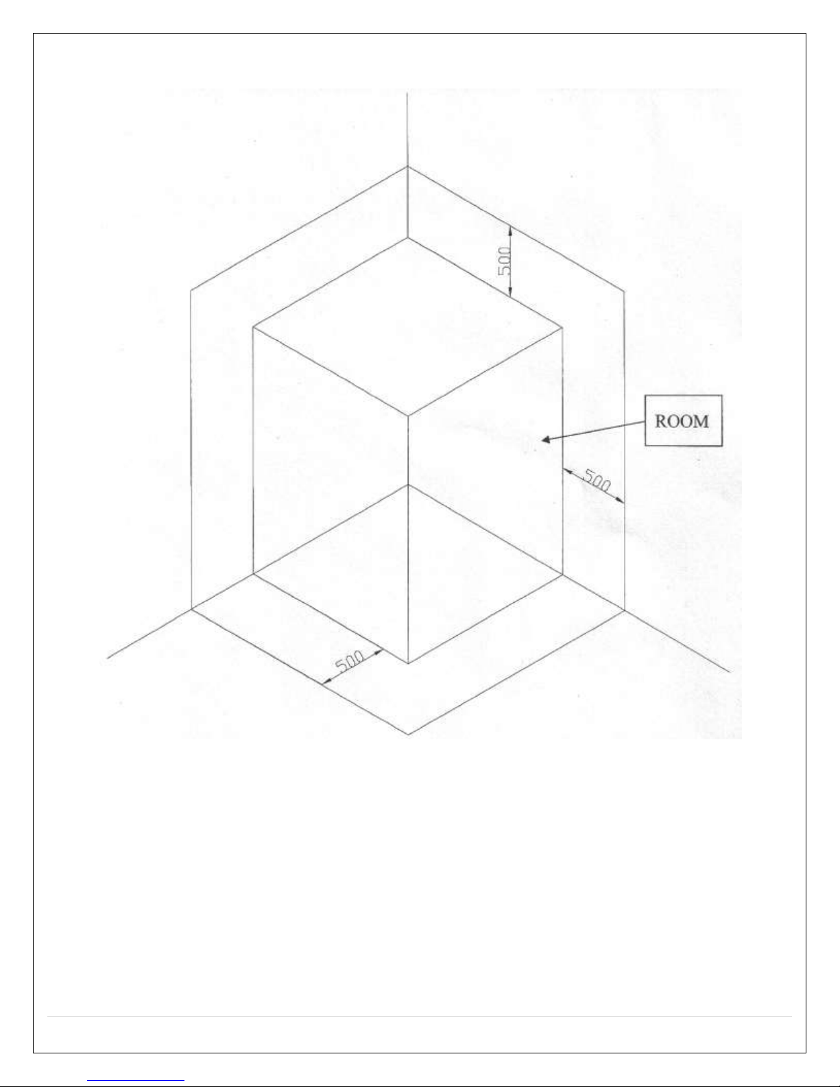
Attention: do not put anything in the safe area, the distance between the top shower cover
and ceiling should be greater than the safe area. Room must be left clear on both sides of the
shower.
8 | P a g e
REV 03/2012
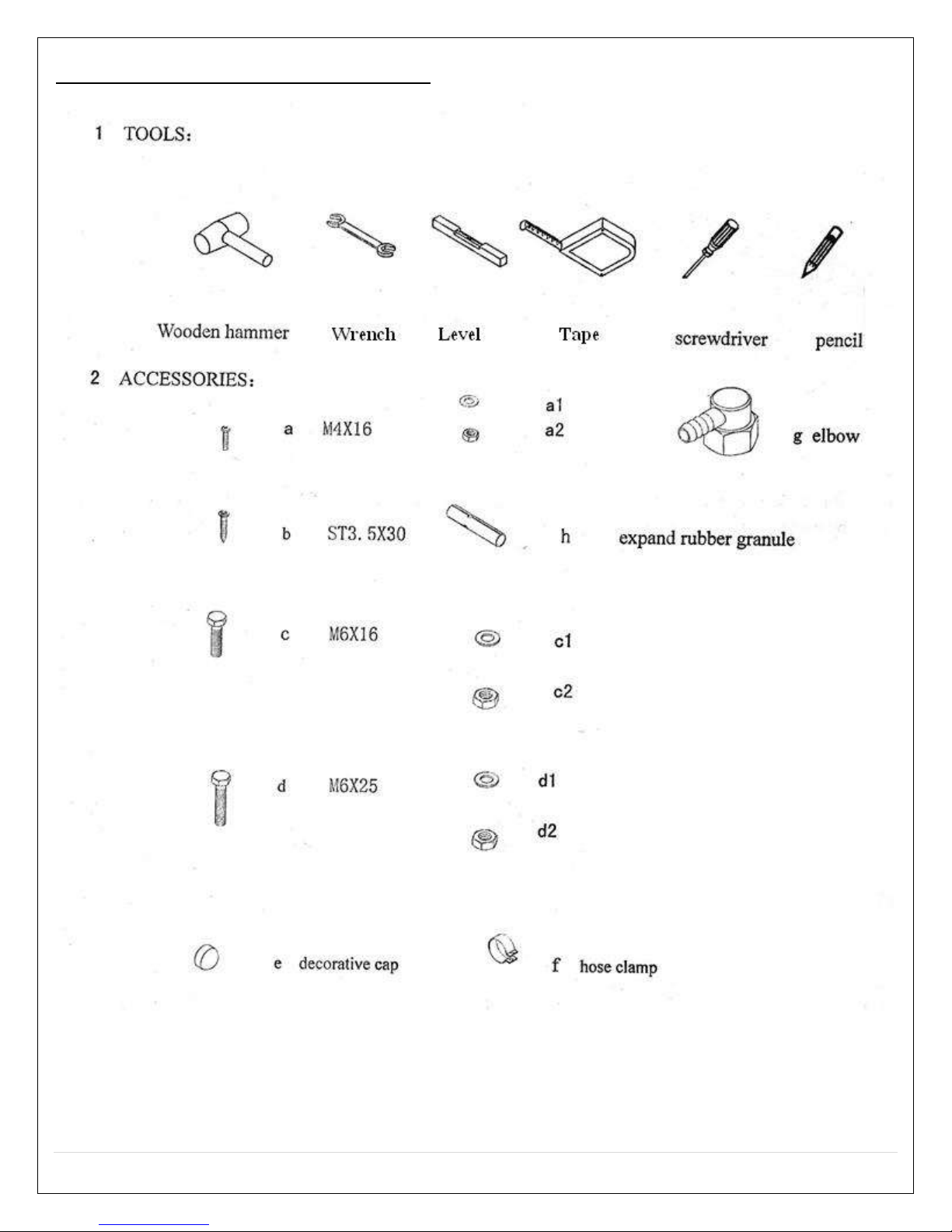
Tools Needed for Installation
9 | P a g e
 Loading...