

Page 1

Installation & Operating Instructions
®
®
C
Steambath Control Models: TSC-250 & TSC-250R
Important: Locate Publication No. 199 “Steam Bath Important Safety Instructions”. This publication includes a Warning
label that the contractor must install on the wall near the entrance to the steam room in a highly visible location. This
label and its additional safety information are packaged with the generator in the envelope containing the installation
!
instructions. If it is lost or missing contact Steamist (201-933-0700) for a replacement Publication No. 199. This publication along with all documents must be left with the owner.
Control Features
1. Display: The digital readout displays the ambient temperature,
set point and cycle time, system status, and diagnostic error
codes.
2. Steam Icon: When illuminated the steam cycle is running.
3. Water Icon: When steam shower is not in use the blue water
icon indicates the **InstaMist feature is on. This is also illuminated during a steam bath cycle.
4. Menu button: Used to change cycle time, turn **InstaMist on or
off and switch between ºF and ºC. When steam is off, pressing
this button will toggle between these settings. The settings are
changed with the up/down arrow buttons.
( *New for 2017 )
Cleaning Instructions: Use a damp cloth and mild soap. Do
NOT use abrasive cleaners which might scratch the surface
or the base of the control.
*If your model TSC-250 control does not match the picture
below, please see Pub. No. 271-D.
**InstaMist option is ONLY available when connecting to a
“TSG” model steam generator (InstaMist function is not
available on the “SMP” models). InstaMist is a preheat
function that keeps the water heated for quick starts.
TSC-250R (Round control)
5. Stop button: Pressing this button stops the current steam cycle
and the Menu mode.
6. User 1 button: Starts the user one cycle and is the up function
when changing Menu settings. Pressing this button while in a
cycle will change the temperature and remaining time left on
that cycle.
7. User 2 button: Starts the user two cycle and is the down
function when changing Menu settings. Pressing this button
while in a cycle will change the temperature and remaining time
left on that cycle.
MENU
__
__
__
__
STOP
21
X
US
IMPORTANT: This control must be installed inside the steam room
for proper operation of the system and will ONLY function with TSG
and SMP model steam generators.
TSC-250 Digital Temperature Control ( 2017 Model )
TSC-250 Digital Temperature Control
1
4
6
03/17
MENU
__
__
__
__
21
STOP
X
- 1 -
2
3
5
7
Pub. No. 271-E
Page 2

Installation Instructions
1.
Pre-Installation - Control Location
a) The TSC-250 Control must be installed inside the
steam room. For convenience the recommended height
from the floor is four feet. Provide a 1½" hole in the wall
at this location (see Figure 1).
IMPORTANT: Multi-conductor cable must be installed
so that the end will not be buried inside the wall. The
unit will not operate unless the control is installed.
2. Electrical Rough-in
a) Locate the multi-conductor cable. Carefully route the
multi-conductor control cable from the steam generator
to the TSC-250 located inside the steamroom (see
Figure 1). Route multi-conductor cable through a ¾"
conduit to protect the cable from damage and to
facilitate replacement if necessary.
3. Control and Cable Installation
a) Locate the previously installed cable and black plastic
strain relief clamp which is in the control packing box.
Locate the knockout on the steam generator for the
control cable (see Figure 3).
b) Place strain relief around cable about seven inches
from the end and insert into the hole. Remove the
protective covering labeled “Remove Before Installation” from the modular jack found on the PC board.
c) Remove the protective cap from the multi-conductor
cable plug. Connect the cable to the modular jack.
d) Close and secure generator cover.
e) Locate Telco Jack at female coupler, on back of the
TSC-250 control. Remove the protective covering
labeled “Remove Before Installation”. Remove protec-
tive cap from cable and plug into jack. Check that the
orientation of the plug properly aligns with the jack. A
snap will indicate the plug is installed correctly (see
Figure 3).
IMPORTANT: Test the control for operation before
continuing on to the next step.
f) Peel adhesive liner from back of the control. Apply the
control to the wall. Press firmly and hold for a few
seconds.
g) After the control is in place, apply silicone (supplied)
around the control to form a watertight seal (see Figure
2).
Installation & Operating Instructions
Figure 1
IMPORTANT: Run the
Control Cable through
a ¾” conduit.
To Steam Generator
Inside Installation:
TSC-250 Control.
Locate away from the
Coupler
direct line of shower
spray and do NOT
1½“ Hole
located four feet
from the floor
Double-Sided
Adhesive Pad
STOP
2
MENU
1
__
X
__
__
__
Figure 2
M
A
D
E
eN
t
1
/
2
NI
LC
E
.U
LF
.S
O .
RA
A
02513 .oN metI
.
.Z
ENOCILIS
Coupler
Control Cable
to Generator
Adhesive Liner
IMPORTANT: The adhesive on the back of the TSC-250 control
will NOT seal this control. It is the responsibility of the installer to
seal this control to the wall with the supplied silicone. Water
damage to the control is not covered by the warranty.
Figure 3 - Cable Installation on Steam Generator
¾" Conduit
To Control
03/17
Modular Jacks:
All modular jacks are
identical and work in
any combination.
Connect to any jack.
- 2-
Pub. No. 271-E
Page 3

Operating Instructions
Installation & Operating Instructions
Operation: Make sure the water and power are turned on.
Simply press USER 1 or USER 2 button to begin the cycle.
Press the Stop button will end the cycle. After a cycle is started
it will take a few minutes for the Steam Generator to heat up
and begin producing steam. This time will be less if the
InstaMist has been ON. During operation the display will show
the ambient temperature.To view the remaining cycle time,
press the Menu button.
Programming: Adjustments can be made to temperature and
cycle time, while a cycle is started. When the temperature is
displayed, the set temperature can be viewed or changed by
momentarily pressing the up or down button. Temperature
adjustments made when USER 1 cycle is started will be saved
to USER 1 and likewise for USER 2. All changes made to the
temperature control are stored in memory until changed again.
The temperature range is 60°F to 125°F (16°C to 52°C). While
a cycle is running, pressing the Menu button will show the
remaining cycle time and this can be adjusted with the up or
down buttons. This time adjustment is only for remaining time
of the current steam bath cycle.
NOTE: The TSC-250 and TSC-250R controls operate and install the same way, only difference between them is the physical shape.
Default Time Setting: The default time is programmed when
the cycle is off using the Menu button. Any adjustments made
to time, when the cycle is off are stored as the new default time
for both users.
InstaMist Setting: The InstaMist feature can be turned on or
off when the steam cycle is in the off mode. To adjust this
setting, press the Menu button until you see the Water Icon,
press the Up or Down button to change this setting. Display
“On” or “OF” will appear. InstaMist keeps the steam generator
warm, for a faster heat up and is ONLY available on the TSG
model steam generators. (InstaMist function is not available on
the “SMP” models)
Fahrenheit or Celsius setting: To change this setting, while
the steam cycle is off, press the Menu button until you see an
“F” or “C” in the display. Use the up or down button to change
the displayed letter, to correspond to your temperature choice.
Press the Stop button to exit the Menu mode. Your last setting
will be saved.
Additional Features
Memory: The temperature set points for USER 1, USER 2, the
default time, and the selection of InstaMist and other settings
are retained even if there is a power failure.
Service Mode: To enter the service mode press and hold the
Menu button for 5 seconds, until a blue dot lights up in the
display. The control is now in the service mode. There are two
features in the service mode. Pressing the Up arrow displays
the program version, pressing the down arrow, restores to
factory default.
Error Messages: This control is programmed with a diagnostic feature to help isolate any potential problems. Errors are
displayed by flashing an “Er” followed by a 2 digit number. The
first digit is the device number. Zero for the control and 1-4 for
the generators. The second digit is the error code for that
device. Error messages “Er 01”, “Er 02”, and “Er 04” indicate a
problem internal to the control. If this occurs, the control
should be replaced. Error messages “Er 03” means the
control could not communicate with a steam generator and
may be a cable connection problem. If this error occurs, check
both ends of the control cable for clean, dry and secure
connections. Dirty contacts can be cleaned with alcohol and a
cotton swab or a toothbrush. This can also happen if the
control is not sealed and the cable connections get wet. Also
make sure the generator is not in test mode. Try resetting the
breaker. Generator error codes are not covered in this
document.
03/17
- 3 -
Pub. No. 271-E
Page 4
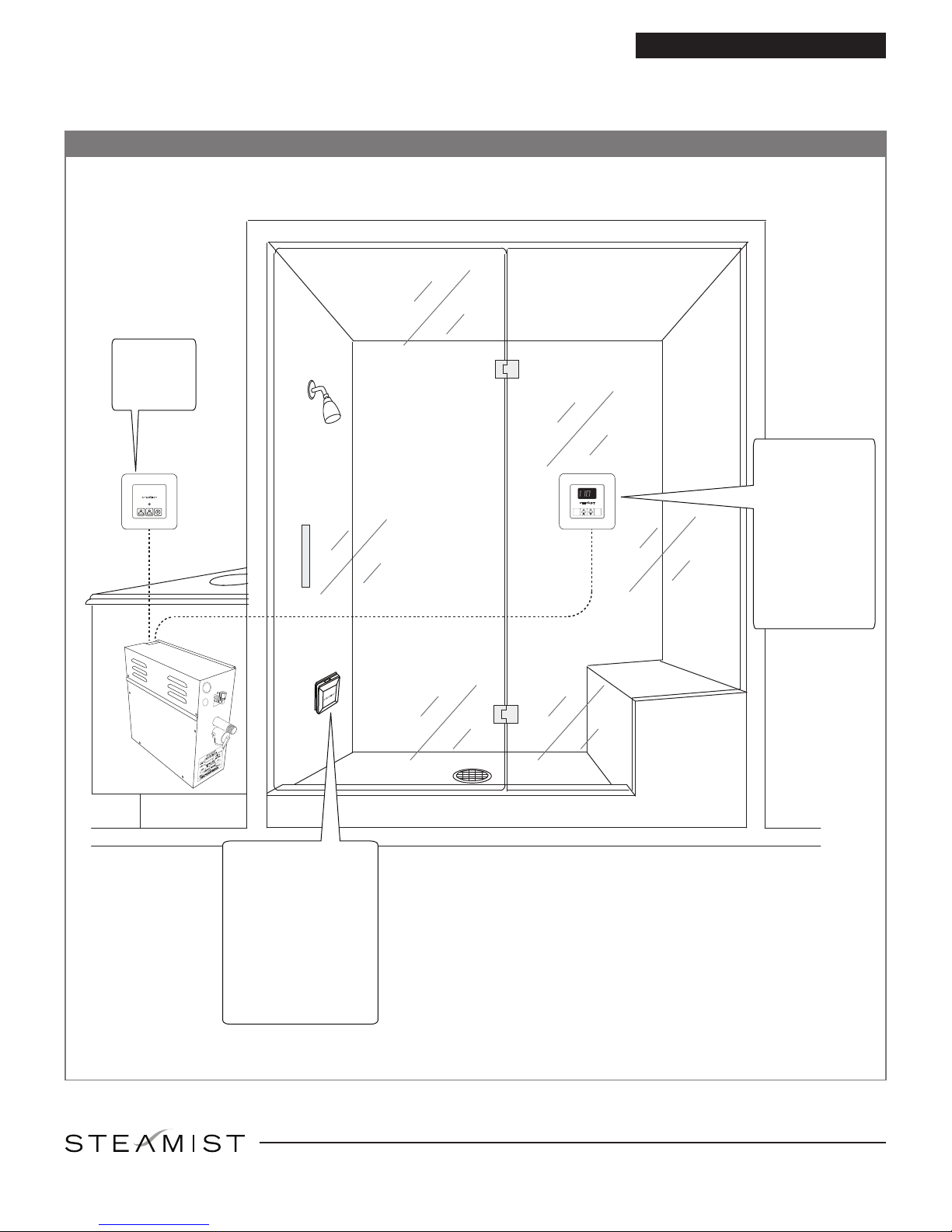
Figure 4 - Installation Suggestions
TSX-220
Auxilary
Outside
Control
1
2
Installation & Operating Instructions
TSC-250 must
be mounted
inside the
STOPXMENU
2
__
1
__
__
__
1
2
X
steamroom.
Locate away
from the direct
line of shower
spray and do
NOT locate
above steam-
head.
Steamhead
Installation
Steamhead should
be mounted 12” to
18" above the
finished floor or 6"
above the rim of the
tub as far from the
bather as possible
All Instructions must be given to the homeowner for future
East Coast Office: 25 E. Union Ave., East Rutherford, NJ 07073 • Tel: 800-577-6478 • Fax: 201-933-0746
®
West Coast Office: Tel: 800-355-6478 • Fax: 661-940-1617
03/17
- 4 -
Pub. No. 271-E
 Loading...