

Page 1

Steambath Control
Model: TC-150
®
C
LISTED 995C
US
Installation and Operating Instructions
WARNING: Elderly persons, pregnant women, or those suffering from heart disease, high blood
!
IMPORTANT: the TC-150 Control will only function with one of the following Steamist steam generator
models: SM-46, SM-79, SM-4, SM-5, SM-7, SM-8, SM-11, SM-12, SM-15, System-18, System-24,
System-30, and all InstaMist Generators.
IMPORTANT: This control must be installed inside the
steam room for proper operation of the system.
4
pressure, diabetes, or who are otherwise not in good health, do not use this device unless
directed to do so by a physician. Also, do not use steambath while under the influence of alcohol.
Control Features
1.
Temperature Display: Indicates steam room or set
point temperature.
2.
Start/Stop Key Pad: Press key pad and generator
will begin producing steam in a few minutes. The
generator will remain on for 30 minutes when used
TEMPERATURE
START
STOP
1
3
2
with the models SM-46, SM-79, SM-4, SM-5, SM-7,
or SM-8 steam generators and 60 minutes for larger
generators. Pressing the key pad a second time will
stop the steam generator.
Steam Icon: Indicates the generator is producing
3.
steam when illuminated. The heater in the generator
and the steam icon will cycle on and off as the
temperature is maintained automatically in the steam
room.
Up/Down Key Pads: Press to adjust the temperature
4.
set point.
TC-150
Digital Temperature Control
Installation Instructions
1. Pre-Installation - Control Location
a)
The TC-150 control must be installed inside the
steam room. For convenience the recommended
height from the floor is four feet. Provide a 1½” hole
in the wall at this location (see Figure 1).
IMPORTANT: Multi-conductor cable must be
installed so that the end will not be buried inside the
wall. The unit will not operate unless the control is
installed.
2. Electrical Rough-in
a)
Remove the multi-conductor cable from the control
packing box. Carefully route the multi-conductor
control cable from the steam generator to the
TC-150 located inside the steamroom (see Figure
2). Route multi-conductor cable through a ¾”
conduit to protect the cable from damage and to
facilitate replacement if necessary.
Cleaning Instructions: Use a damp cloth and mild soap.
Do NOT use abrasive cleaners which might scratch the
surface or the base of the control.
IMPORTANT: Run the
Control Cable through
a ¾” conduit.
1½“ Hole
located four feet
from the floor
Figure 1
TC-150 Digital
Temperature Control
Double-sided
Adhesive Pad
To steam generator
Coupler
07/07
- 1 -
Pub. No. 122-A
Page 2

3. Control and Cable Installation
a)
Locate the previously installed cable and black
plastic strain relief clamp which is in the control
packing box. Locate the knock-out on the steam
generator for the control cable (see Figure 2).
b)
Place strain relief around cable about seven inches
from the end and insert into the hole. Remove the
protective covering labeled, “Remove before
installation,” from the modular jack found on the PC
board.
c)
If TC-150 is used in conjunction with the optional
TC-125 control or Dual System, plug the splitter
into the modular jack, this will allow two cables to
be plugged into the PC board (see Figure 2).
IMPORTANT: When used with the Optional
TC-125 control or Dual System, the Steamist
supplied splitter must be used. Locally purchased
telephone splitters will NOT work and void the
warranty.
d)
Remove the protective cap from the
multi-conductor cable plug. Connect the cable to
the modular jack.
e)
Close and secure generator cover.
f)
Locate Telco Jack at female coupler, on back of the
TC-150 control. Remove the protective covering
labeled “Remove before Installation”. Remove
protective cap from cable and plug into jack.
Check that the orientation of the plug properly
aligns with the jack. A snap will indicate the plug is
installed correctly (see Figure 2).
WARNING: Test the control for operation before
continuing on to the next step.
¾“ Conduit
Multi-conductor
Control Cable
To Control
(25 feet)
Figure 3
Coupler
Adhesive Liner
Control Cable
to Generator
g)
Peel adhesive liner from back of the control. Apply
the control to the wall. Press firmly and hold for a few
seconds.
h)
After the control is in place, apply silicone (supplied)
around the control to form a water tight seal.
M
A
I
t
D
N
e
m
e
E
t
N
I
1
C
N
/
o
2
L
.
U
F
3
E
L
1
.
A
S
.
5
O
2
.
R
A
0
Z
.
.
S
L I
I
C
O
N
E
Figure 4
IMPORTANT: The adhesive on the back of the
TC-150 control will NOT seal this control. It is the
responsibility of the installer to seal this control to the
wall with the supplied silicone. Water damage to the
control is not covered by the warranty.
Steamist splitter
supplied with Optional
TC-125 control or Dual
System.
Modular Jack
Figure 2
Cable Installation
on Steam Generator
07/07
Printed
Circuit Board
Knock-outs for
Strain Relief
Clamps
Protective Covering
“Remove Before
Installation”
Pub. No. 122-A- 2 -
Page 3
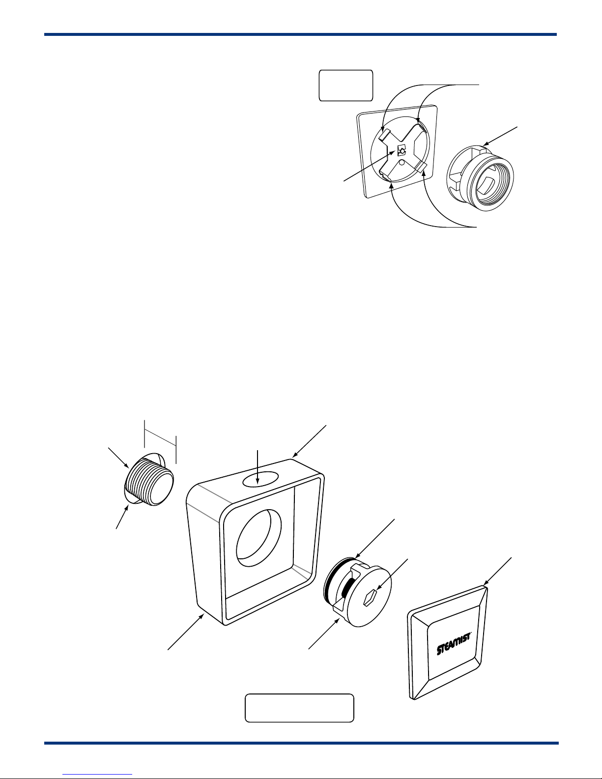
1. Make sure the 3/4” nipple protrudes beyond
the tile approximately 1/2”. (See Figure 5)
2. Wrap the nipple with pipe sealant tape.
Figure 6
Center Hub
Installation
IMPORTANT:
Install top first
3. Put a bead of silicone around the outer edge
of the Back Plate (see Figure 5) and center the
back plate over the pipe in an upright position.
While holding it in place screw the Center Hub
on to the nipple, using a ⅜” Hex Key to tighten.
4. The Center Hub MUST be aligned with the
four walls in the vertical and horizontal position.
(See Figure 6) Make sure the steamhead o-ring
is fully seated into the Back Plate. If the nipple
is sticking out too far the o-ring will not make a
proper seal and the nipple must be adjusted.
5. Apply a small amount of silicone at the back
center point of Cover Plate. This will aide in
preventing movement of this plate.
(See Figure 6)
MUST be vertical
Apply a small
amount of
silicone to
prevent
movement
After inserting the top
snap in the bottom.
6. Place the Cover Plate over the Center hub.
This is accomplished by first hooking the top
and then snapping the bottom into place.
7. Adjust the Back Plate and Cover Plate to line
up squarely and clean excess silicone with
rubbing alcohol.
3/4” NPT (Brass Pipe)
Must use sealant tape.
Apply silicone around
the steam pipe to form a
water tight seal.
1/2”
Back Plate
Aroma Therapy
Reservoir
Center Hub
Apply silicone around
the back edge of Back
Plate to seal and
prevent movement.
O-Ring MUST
seal to inside of
the Back Plate.
3/8” Hex key
Hole
Cover Plate
07/07
Figure 5
Steamhead Installation
- 3 -
Pub. No. 122-A
Page 4

Operating Instructions
Operation
Make sure the water and power are turned on. Simply
press the Start/Stop keypad to begin the previously
programmed cycle. Pressing the Start/Stop a second
time will cancel the cycle. After a cycle is started it will
take a few minutes for the Steam Generator to heat-up
and begin producing steam. During operation the display
will show the ambient temperature. The heat icon will
cycle on and off as the temperature is maintained.
Additional Features
Memory
The temperature set point is retained even if there is a
power failure.
Fahrenheit/Celsius
The temperature display may be changed to Fahrenheit
or Celsius by simultaneously pressing and holding the up
and down keypad for 5 seconds while the system is off.
The display will show the current setting “F” or “C” and
then alternate when the change is complete.
Programming
Adjustments can be made to the temperature control
while the system is on or off. Any time the temperature is
displayed, it can be adjusted by simply pressing the up or
down keypad. All changes made to the temperature
control are stored in memory until changed again. The
temperature range is 50°F to 130°F (10°C to 55°C).
Error Message
This control is programmed with a diagnostic feature to
help isolate any potential problems. Error messages E0,
E1, E2 and E3, indicate a problem internal to the control.
If this occurs the control should be repaired or replaced.
Error messages E4, E5 and E6 indicate a communication
problem with the steam generator. If this error occurs,
check both ends of the control cable for clean, dry and
secure connections. Dirty contacts can be cleaned with
alcohol and a cotton swab or a toothbrush. This can also
happen if the control is not sealed and the cable
connections get wet.
All Instructions must be given to the homeowner for future use.
Optional Outside
Steamhead Installation
Steamhead should be mounted
18” above the finished floor or 6”
above the rim of the tub as far
from the bather as possible
Installation
TC-125 Control
START
STOP
Installation Suggestions
TEMPERATURE
START
STOP
Inside Installation
TC-150 Control. Locate away
from the direct line of shower
spray and do NOT locate
above steamhead.
East Coast Office: 275 Veterans Blvd., Rutherford, NJ 07070 ● Tel: (800) 577-6478 ● Fax: (201) 933-0746
West Coast Office: 315 W. Pondera St., Suite F, Lancaster, CA 93534 ● Tel: (800) 355-6478 ● Fax: (661)940-1617
07/07
Figure 7
Installation Suggestions
Pub. No. 122-A- 4 -
 Loading...