

Page 1
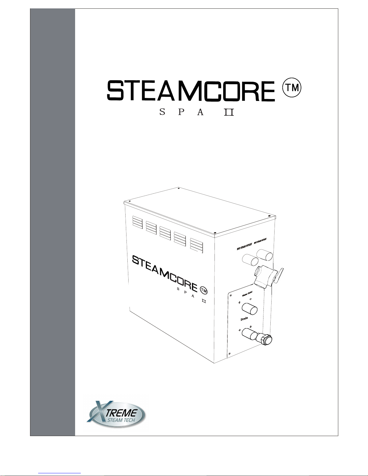
OPERATION & INSTALLATION MANUAL
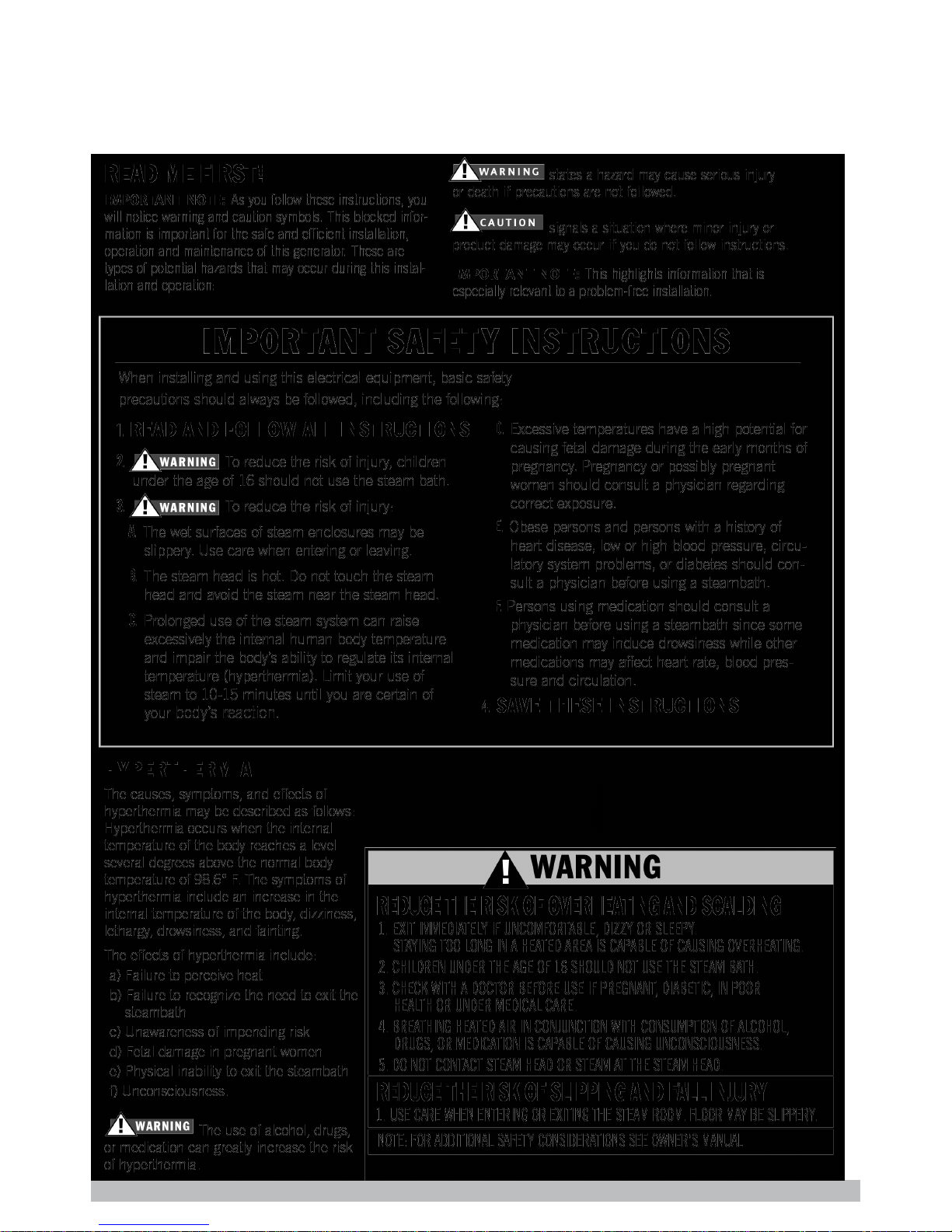
STEAM GENERATORSTEAM GENERATOR
aobsessed with qualiy...
aquality of life
TM
Auto Drain Equipped - Whisper Quiet - Quick Start - Continous Steam
Page 2
SAUNACORE PHONE: 905-951-6662 www.saunacore.com
Page 3
ÖØ
Òª
:
Prologue
Users instruction
Óû§ÐëÖª
¾¯
¸æ
:
Caution:
We are not responsible for the malfunction and damage from
installation that does not comply to the user manual.
Important:
Choosing a right location
Install an exhaust fan outside of the steam room so it can expel
the excessive steam from the shower room.
User Manual
Certified to CAN/CSA Std. No. 88
Conforms to UL. Std. 499
It is strongly recommended that the water intake solenoid be connected to a water supply using a braided hose line.
Teflon tape is required to make a liquid tight seal between the threads and a rubber gasket (washer) is used to seal
between the solenoid and the braided hose attachment. Incorporate thread sealant (teflon tape) on both the water intake
and drain solenoid for a tight seal to avoid leaks.
Technical Hotline 905-951-6662
1. Make surethe model and output are correct, including the voltage.
2. Make sure the power are matched with the steam room dimensions. Pay attention to the
steam room's cubic footage and wall finish materials. If you have any problems, please refer
page 11 for steam generator sizing and selection.
3. Read this entire manual before installation.
4. Saunacore will not be responsible for any damage or malfuntion due to the product by improper
installation.
5. Steamcore SpaII Series are pre-tested and inspected prior to packaging, please inspect package when received
to assure all is in proper condition. If you find any damage to the package, immediately put in a claim with the
delivering (courier) company for a claim of compensation.
6. The steam generator use in a heated indoor space only.
7. This unit must be completely installed with unions for easy removal, the steam lines must be 3/4" diameter
pipe for each steam line. Do NOT reduce steam line pipe diameter, do not connect steam lines, and a pressure
reducer valve must be used to reduce water pressure to 15-20 psi. Do NOT heat solenoids with any flame or
soldering torch.
Recommended installation locations.
1. The distance between the steam room and the steam generator should be 20ft or less. The steam generator is
supplied with a control cable of 20ft long. It can be extended if needed to a max of 60ft (with purchase of
additonal 20ft length control cables).
2. The steam generator should NOT be installed inside the steam room.
3. Do NOT install the steam generator outdoors or any place that will influence the operation, function, security
of the steam generator by the surrounding environment.
4. Do NOT expose generator to any place it may freeze, or near any combustible objects or chemicals.
5. Install steam generator in a dry well ventilated location.
NOTE: Do NOT apply any heat or source of flame to the intake/drain solenoids during installation. This can cause
damage or malfunction of components.
1
Page 4
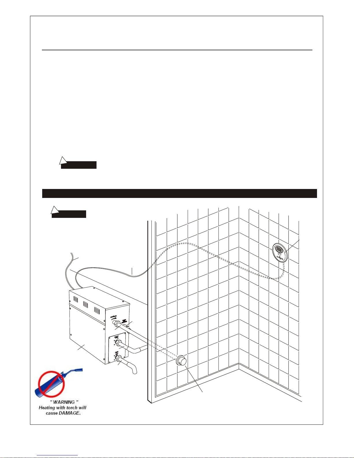
Steam generator
Water Drain Valve
Water Inlet Pipe
Steam outlet pipe
Control panel
Supply
Steam Outlet
Pressure
relief
valve
!
The steam generator( including the controller) comply with CE , CSA
and
UL certificat ion standards.
!
Attention:
Attention:
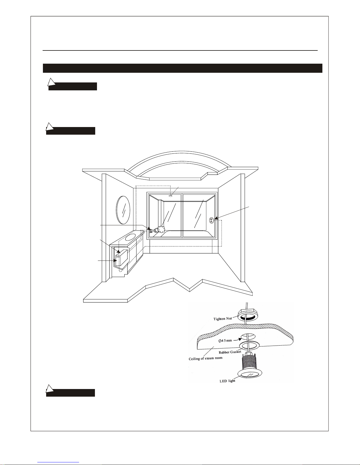
Installation drawing of the steam generator
The drawing is only
for sample. As for practical
design of steam room, please
consult with qualified designer,
architect or builder.
User Manual
Control Cable
(20ft max)
7. The steam generator should be securely mounted. Make adequate care that the generator
is stable and level, horizontally. The steam generator has hanging holes in the back side for
mounting onto a wall.
8. The steam generator requires a minimum of 12 inch clearance of space on both sides, top and front.
9. The steam generator must be installed in a place that is easily accessible, and convenient for removal,
or disassembly.
10. The installation area must have access to a drain.
11. The steam line(s), pressure relief valve, drain valves, water supply line, and steam outlets
are VERY HOT during and after use for some time. Keep the steam outlets away from any
body parts or bathers. Bodily injury or burn may occur if coming into contact or in the visinity
of the steam nozzles. Provide appropriate protection to avoid bodily injury.
(10.5 kw and higher require 2 steam outlets)
Intake or Drain Valves 2
Page 5
×°ÔÚÁÜÔ¡ÕßÈÝÒ×¾-
ÕßµÄΣÏÕ¡£
Òâ
:
!
Õô
°²×°ÔÚÁÜÔ¡ÕßÈÝÒ×¾-
³£
ÓÃÕßµÄΣÏÕ¡£
×¢
Òâ
:
!
Installation of pipeline
The installation of all the pipes should be done
by
a qualified
licensed plumber.
Warning:
Attention:
Atte ntion:
Attention :
User Manual
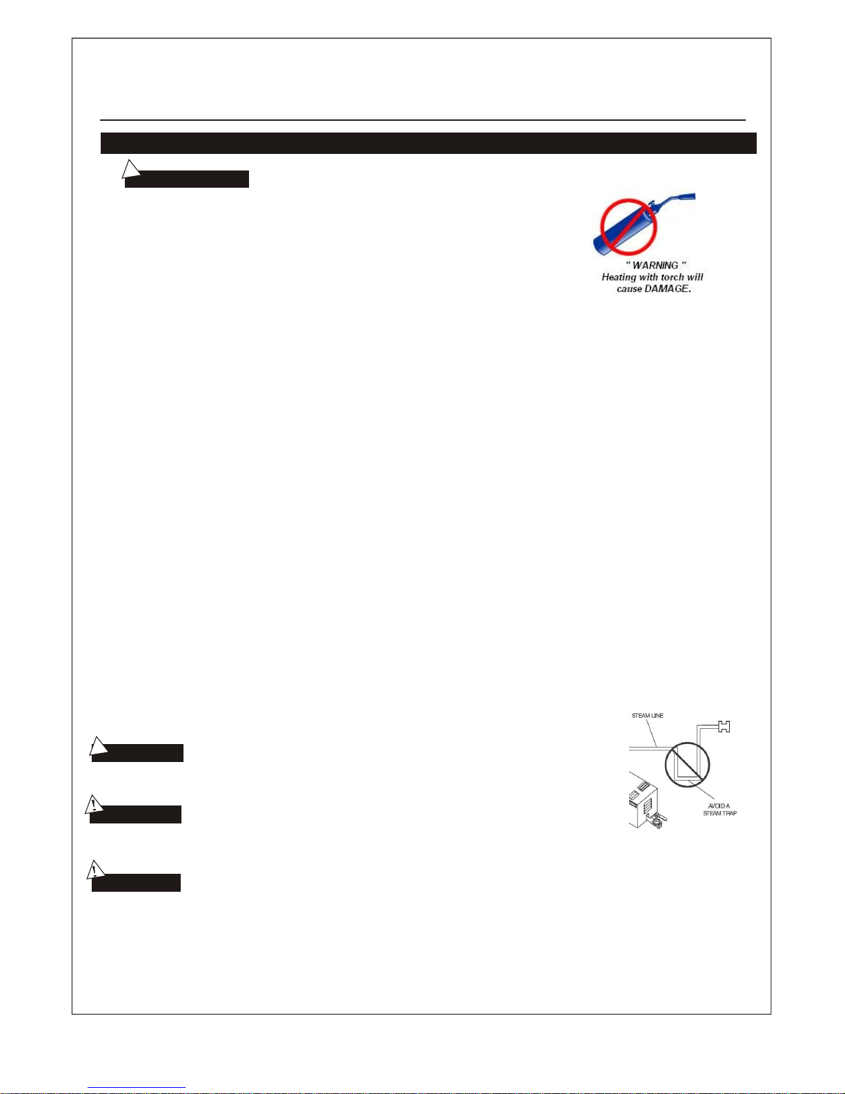
DO NOT HEAT AUTO FILL / DRAIN VALVES WITH TORCH DURING INSTALLATION.
This will cause damage to the plastic solenoid valve which will cause malfuction or leakage.
WATER SUPPLY LINE (1/2" WITH SHUT OFF VALVE)
1. Connect cold water supply with a shut off valve that is located in a that makes it
easily operated in an emergency.
2. Make sure the water supply line is clean before attaching to steam generator intake solenoid.
It is recommended that a 3/8 inch braided hose is used to supply water to the steam generator.
3. The water pressure should be between 15-20 psi. If necessary, decrease the pressure accordingly. Excess
pressure may cause leakage or malfunction of parts. The water flow rate should be aprox 8 gpm.
4. If necessary, install equipment to prevent water hammer noise. Also install an approved backflow preventer
as required by local codes. It is suggested that a thread on braided hose (3/8") with a rubber washer be used
for the water supply line attachment to the intake solenoid. Create a tight seal between the two fittings.
STEAM LINE PIPE (PIPE DIAMETER: 3/4" PER STEAM LINE - NO LESS!)
1. Do NOT install any valves in the steam line pipes. The steam should never be obstructed.
2. Steam generators up to 9KW require (1) 3/4 inch diameter steam line, 10.5 KW and higher steam generators
require (2) 3/4 inch diameter steam lines. Do NOT use or install steam lines in any configuration, in any less diameter
pipe, or connect them together.
3. The steam lines must be 3/4 inch diameter, the steam heads (nozzles) are 3/4 inch threaded. Steam lines must be
copper or brass material. Do NOT use ABS, galvanized, or PVC pipe. Use threaded unions to install all components
of the steam generator.
4. If steam lines are insulated, the insulating materials should be resistant to a temperature of no less then 250F.
5. The steam lines should be installed horizontally with a slight incline to allow condensate to run off. Incline can be towards
the steam room or the steam generator. Do NOT allow steam pipe to sag, or create any sort of trap that will allow condensate
to build up and block steam flow within the steam lines.
6. The shorter the steam lines, the better performance of the steam genarator. Keep the number of elbows and abrupt turns in
the steam lines to a minimal. Do NOT combine the steam lines if the generator has more then one steam line, do NOT attach
the steam line(s) to the pressure reducer valve line, or drain line.
Do NOT install steam line in an upper or lower direction repeatedly. This will
affect the output of steam and can create a blockage to the flow of steam.
Avoid installing the steam heads (nozzles) in an area that will come into contact
with any body parts or bathers traffic. Add appropriate protection to avoid bodily
injury or burns. It is VERY HOT in the vicintiy of the steam heads outlets.
The steam nozzles should be installed between 10 - 12 inches high from the finished floor. If
the steam bath is within a bath tub enclosure, the steam nozzles should be minimum 6 inches above
the bath tub. If the steam shower materials is acrylic or non-heat-resistance material, install
additional heat insulators.
The steam nozzles need to be intalled so the steam outlet escapes down towards the floor.
Do NOT install with any wrench or tool that will damage it finish. Best to hand tighten and
silicone to the wall finish. Do NOT use corrosive materials to clean the steam nozzle(s) or any
harsh cleaning products.
Flush water supply line before connection to eliminate sediments.
If necessary, install a Hydro pneumatic device which reduces pressure spikes.
Steam nozzles need to be a minimum of 6 inches from a corner.
3
Page 6
!
!
Important:
1. Please consult your distributors of building materials like acrylic, fiber glass or other
anti-heat sheet about the installation position of steam nozzle. It is suggested that MS103412 anti-heat material can be used.
2. In the entire steam room, it is required that steam must not leak out. The pipes, its
accessories and the holes in the wall should be airproof by applying silicone so
that no steam will enter the holes in the wall.
Attention:
User Manual
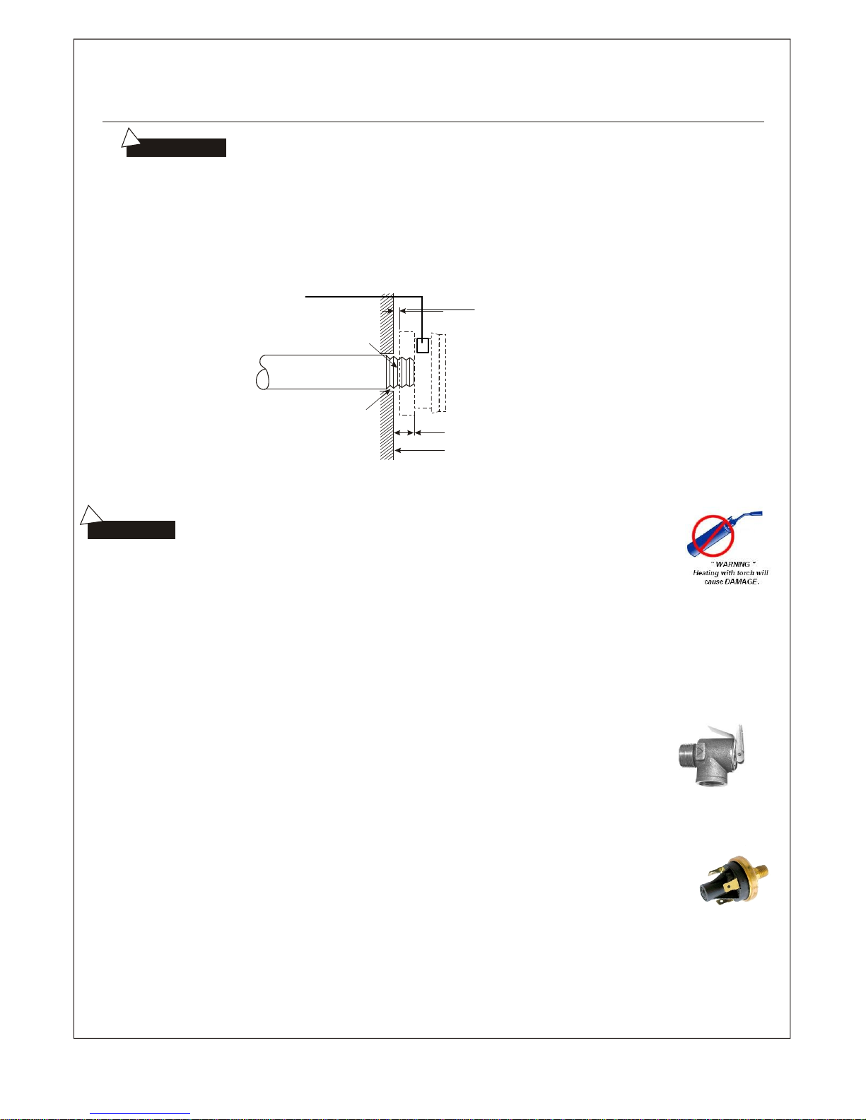
DO NOT HEAT AUTO FILL / DRAIN VALVES WITH TORCH DURING INSTALLATION.
Aroma Essence Reservoir
(apply a few drops prior to heating)
If non-heat-resistant material such as acrylic
is used a wall material, create a gap of no less
then 1.4" and fill with silicone.
Inside wall of steam room.
Use silicone to fill in the gaps in the wall
to achieve the proper water proofing
and damp proof effect.
Apply Silicone
The drain pipe should not incline to prevent gravity flow of draining water.
This may cause damage, leakage or malfunction to intake/drain solenoid valves
DRAIN PIPE: (1/2 inch diameter)
Steam generators up to 9 KW are equipped with an auto drain solenoid valve. The steam generators 10.5 KW and higher
are also equipped with an auto drain solenoid valve, plus an additional manual drain port that is capped. The manual drain port
is to remain capped at all times. This secondary port is for back up manual draining if required for
maintenance use only.
SAFETY PRESSURE RELIEF VALVE: Rated 15 psi.
1. Pressure relief valve is a safety device in order to prevent too much pressure build up within
the steam generator. Build up of pressure can be created by many different reasons; steam line
line blockage, undersized steam line pipr diameter, steam line traps, or vandalism. This build up
of excessive back pressure may cause the auto & manual high temperature limiting switches to
trip and cut power to the heating elements to stop producing steam.
2. The steam generator is shipped with plastic caps over the steam outlets, these are to be removed
and discarded only when making connection to the steam lines. The purpose of these caps is to
avoid any particles getting into the boiler tank while installing or handling the steam generator during
installation.
3. Steam bath generators that are 18 KW and Higher will have a factory installed pressure switch. This
pressure switch will cut power to the steam generator heating elements when the internal steam pressure
within the boiler tank or steam line(s) reaches over the manufactures recommended limit. The switch will
reset automatically when the excessive pressure has been substantially reduced. This will re-occure until
the cause of excessive pressure has been rectified. Usuall causes are listed in point 1.
4. Safety pressure relief valve is an automatic system that is actuated by pressure in order to prevent steam pressure
increasing in the interior of the generator. The pressure limit range of the saftey is 15 PSI and the pressure will begin
to decrease if pressure should come over this value. If it is allowed by local codes, provide the safety valve with exterior
drainpipe. Do NOT dismantle the pressure relief valve while generator is in operation. To maintain the proper automatic
operation of the safety valve, make sure the safety valve connection pipe is smooth.
4
Page 7
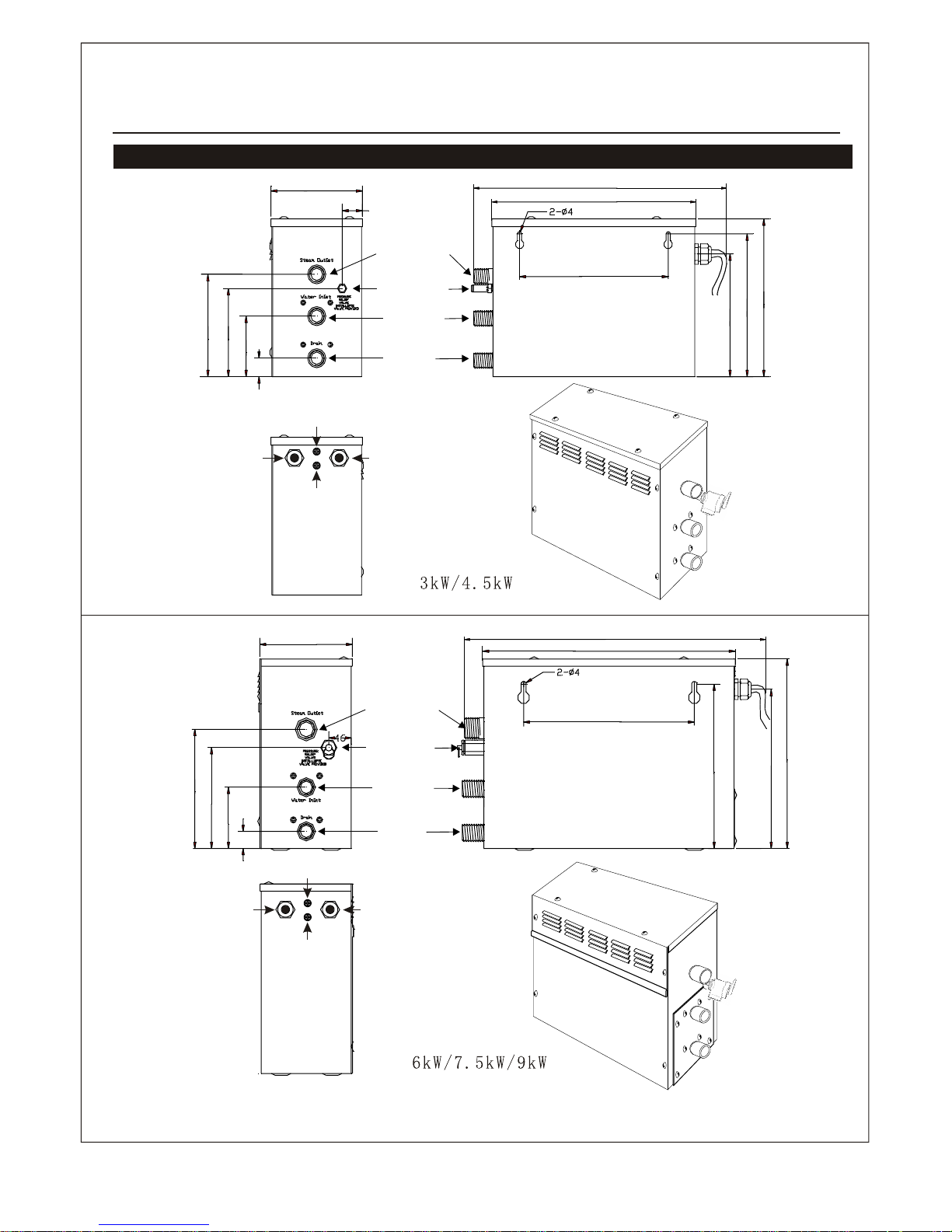
Steam generator blue print.
Safety valve
Steam outlet
Water inlet
Water
drainage
160mm
148mm
98mm
25mm
35mm
130mm
209mm
230mm
244mm
260mm
395mm
Fuse for wire power supply
Power wire hole
Controller wire
and light wire hole
304mm
Safety valve
Steam outlet
Water inlet
Water
drainage
213mm
190mm
115mm
29mm
156mm
260mm
307mm
315mm
335mm
465mm
383mm
Fuse for wire power supply
Power wire hole
Controller wire
and light wire hole
Fuse for wire
power supply
User Manual
Fuse for wire
power supply
(metal conduit connector
required)
(metal conduit connector
required)
5
Page 8
!
!
!
Electrical requirements:
All the connections must be in accordance with national and local
electricity consumption code and be installed by professional licensed electricians.
Attention:
to facilitate maintenance, keep the steam engine clean. If the information
provided is limited, do not touch the pipeline and electric equipment.
Attention:
Caution: to avoid damage to the equipment, do not connect strong electric current
directly to the components.
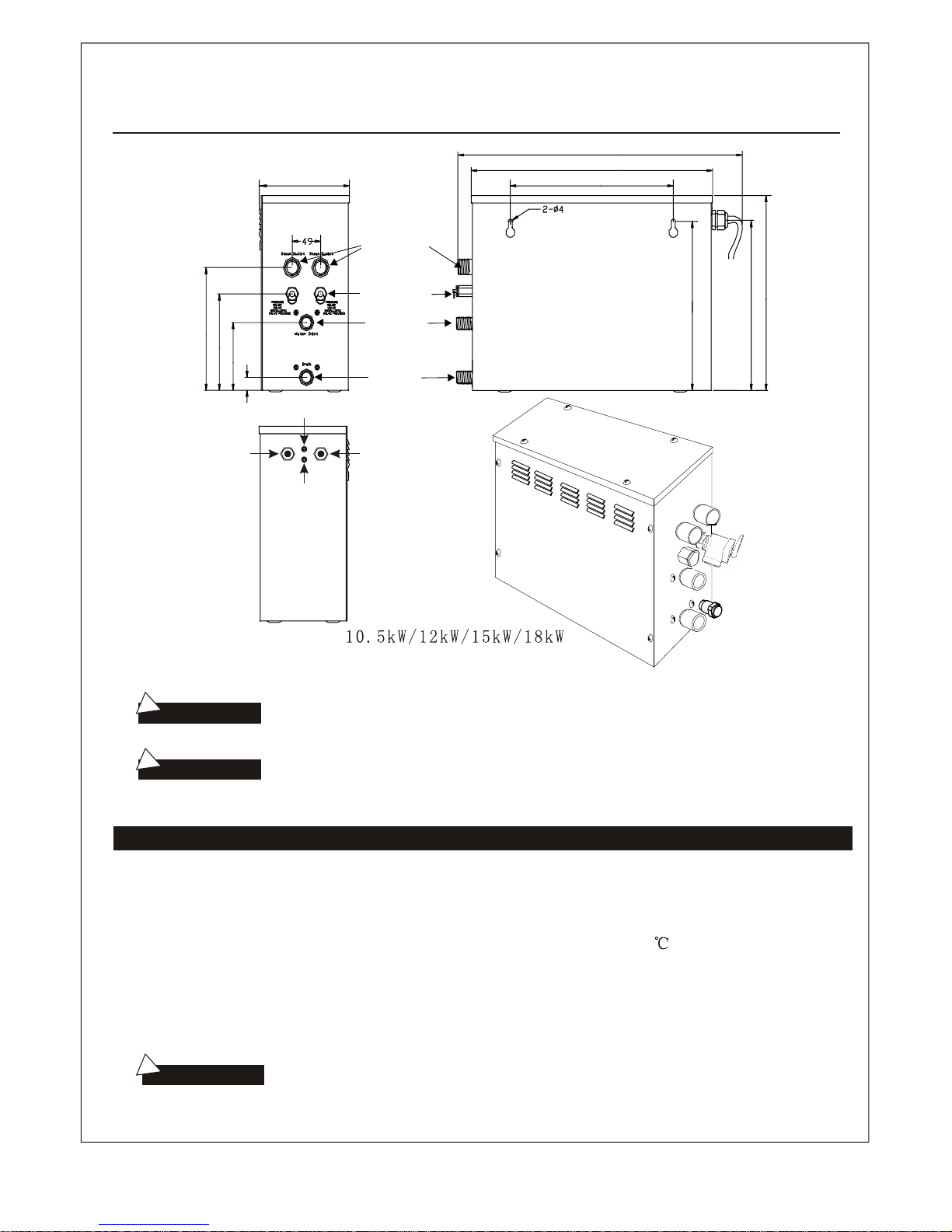
510mm
435mm
Steam outlet
Safety valve
Water inlet
Water
drainage
Fuse for wire power supply
Power wire hole
Controller wire
and light wire hole
300mm
340mm
350mm
385mm
205mm
265mm
215mm
142mm
28mm
User Manual
Fuse for wire
power supply
(metal conduit connector
required)
ELECTRICAL SUPPLY:
1. Test the voltage of electricity supplied to the steam generator, make sure the correct voltage is supplied
to the steam generator. Make sure ALL connections have been adequately torqued.
2. Insulated copper wire should be used with an anti-heat temperature of no less then 90 and a specified
voltage of 300V. Refer to your national or local electrical codefor specifications.
3. Intall an independant circuit breaker between the power supply and the steam generator unit in order to
provide an electricity supply with overload protection and electricity leakage protection.
4. A suitable metal conduit with connector should be used for the main power wiring connections. ALWAYS
disconnect the main power supply to the steam generator prior to attempting any service to the generator.
6
Page 9
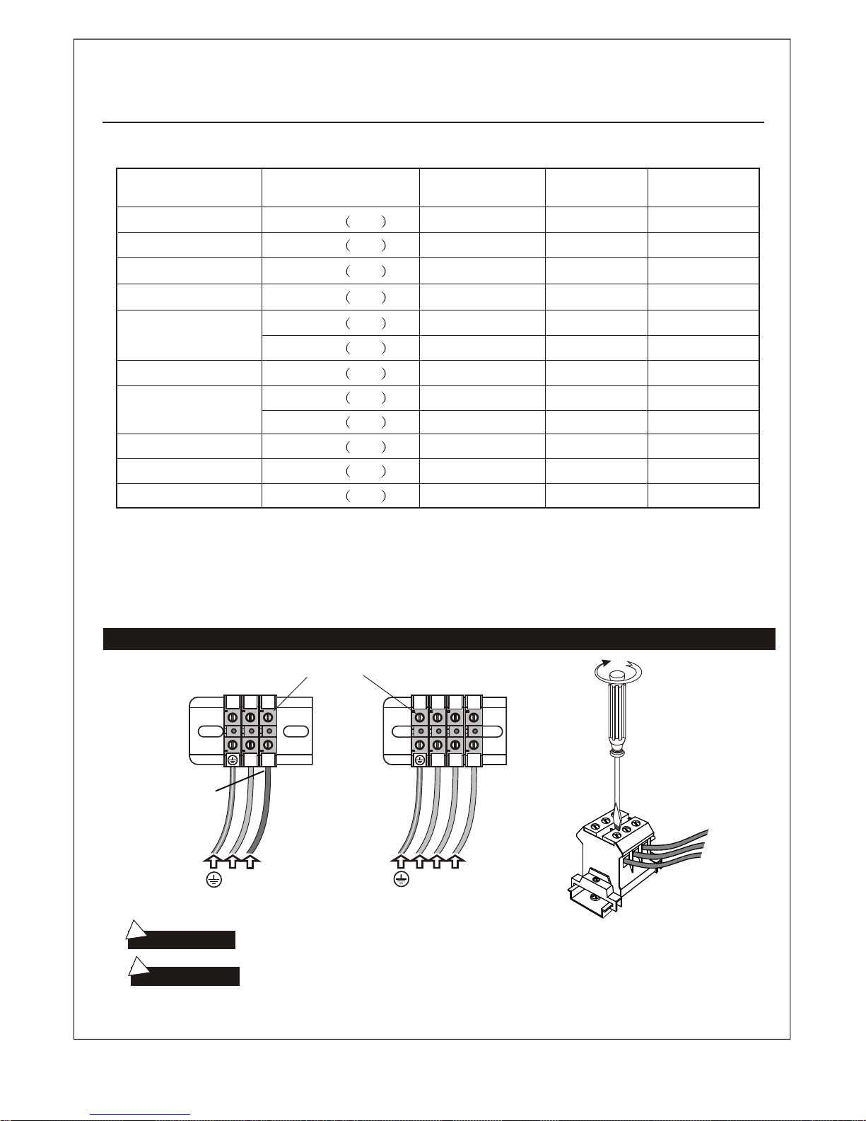
!
Ampere Meter
!
The data provided above are for 240V(1PH) and 208V(3PH). Consult the manufacturer for
three-phased electricity or electric voltage of other specifications. Within the steam generator,
install an independent circuit breaker so as to provide an electricity supply with
overflow protection and electricity leakage protection (ground fault interrupter.)
Power Supply Wire Connection
To avoid damage to the equipment, do not connect strong electric
current to the component directly.
This drawing is for explanation only. For actual installation, refer to
national and local electricity consumption codes by professional licensed electricians.
Attention:
Warning:
240V~ 1PH
240V~ 1PH
240V~ 1PH
240V~ 1PH
240V~ 1PH
208V~ 3PH
240V~ 1PH
240V~ 1PH
208V~ 3PH
12.5A
18.75A
25A x 3
Type
Applicable space of
3
the room (m )
Electricity
supply
Electric
current (A)
L1
L2
L3
(240V~ 1PH)
(208V~ 3PH)
L1
L1 L2 L3
Power connection terminal
User Manual
3kW
4.5kW
6kW
7.5kW
9kW
10.5kW
12kW
13.5kW
15kW
18kW
208V~ 3PH
208V~ 3PH
208V~ 3PH 18~22
15~20
14~18
12~15
12~15
10~13
8~12
8~12
6~10
5~8
4~7
3~6
25A
31.25A
37.5A
43.75A
50A
33.3A x 3
37.5A x 3
41.7A x 3
50A x 3
L2
L1
L2
The total connected load should not be more then 80% of the rating of the overcurrent devices.
European Connection
( L2 = N "Neutral")
7
Page 10
J2-1
J2-2
J1-2
J1-1
J1J2
S S
Supply
Red
Black
Red
Black
Red
Red
To Control Panal
Fill water valve
Drain water valve
Terminal Block
Yellow/Green
Red
Black
Red
Black
Y ellow
Red
Black
Red
Red
Red
Red
Water Level Sensor
Red(Short Pin)
Black(Long Pin)
Yellow(Middle Pin)
Red
Black
Red
Blue
Brown
Red
Light
J1-1
J1-2
J1
S S
L1
G
Supply
Red
Red
Black
To Control Panal
Fill water valve
Drain water valve
Terminal Block
Yellow/Green
Red
Black
Red
Black
Y ellow
Red
Black
Red
Red
Red
Red
Water Level Sensor
Red(Short Pin)
Black(Long Pin)
Yellow(Middle Pin)
Black
Red
Blue
Brown
Red
Light
J1-1
J1-2
J1
S S
Supply
Red
Red
Black
To Control Panal
Fill water valve
Drain water valve
Terminal Block
Yellow/Green
Red
Black
Red
Black
Y ellow
Red
Black
Red
Red
Red
Red
Water Level Sensor
Red(Short Pin)
Black(Long Pin)
Yellow(Middle Pin)
Black
Red
Blue
Brown
Red
Light
L2
Black
Black
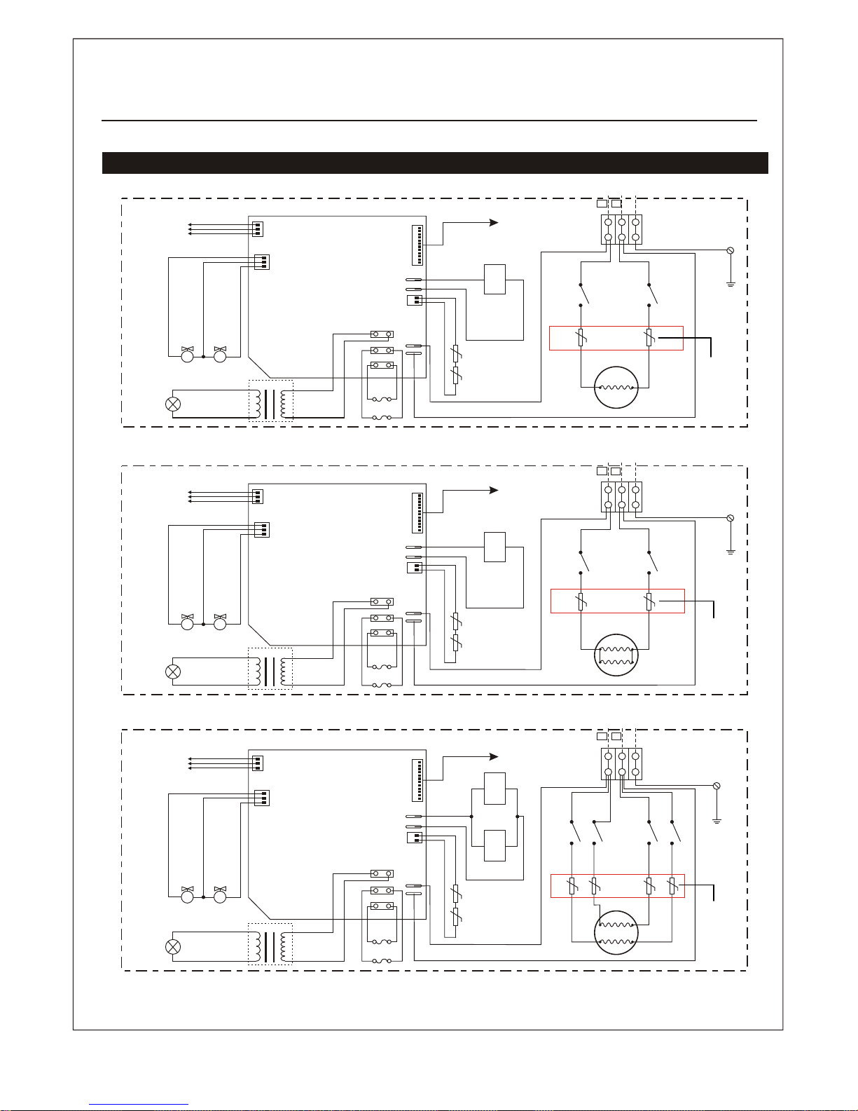
Wiring Diagram 240V(1PH)
N L
L1
G
L2
N L
L1
G
L2
N L
Optional
Optional
Optional
Steamcore Spa ** 3kW (240V - 1PH)
Steamcore Spa ** 4.5kW (240V - 1PH)
Steamcore Spa ** 6kW / 7.5kW / 9kW (240V - 1PH)
Steamcore Spa **
auto reset
hi-limit
auto reset
hi-limit
auto reset
hi-limit
manual
reset
hi-limit
manual
reset
hi-limit
manual
reset
hi-limit
European Connection
( L2 = N "Neutral")
8
Page 11
J1-1
J3-2
J2-2
J1-2
J1
S S
Red
Black
Red
Black
Red
Red
To Control Panal
Fill water valve
Drain water valve
Terminal Block
Yellow/Green
Red
Black
Red
Black
Y ellow
Red
Black
Red
Red
Red
Red
Water Level Sensor
Red(Short Pin)
Black(Long Pin)
Yellow(Middle Pin)
Red
Black
Red
Blue
Brown
Red
Light
Red
Red
Supply
J2J3
J2-1
Black
J3-1
Black
Black
Black
L1
G
L2
N L
Optional
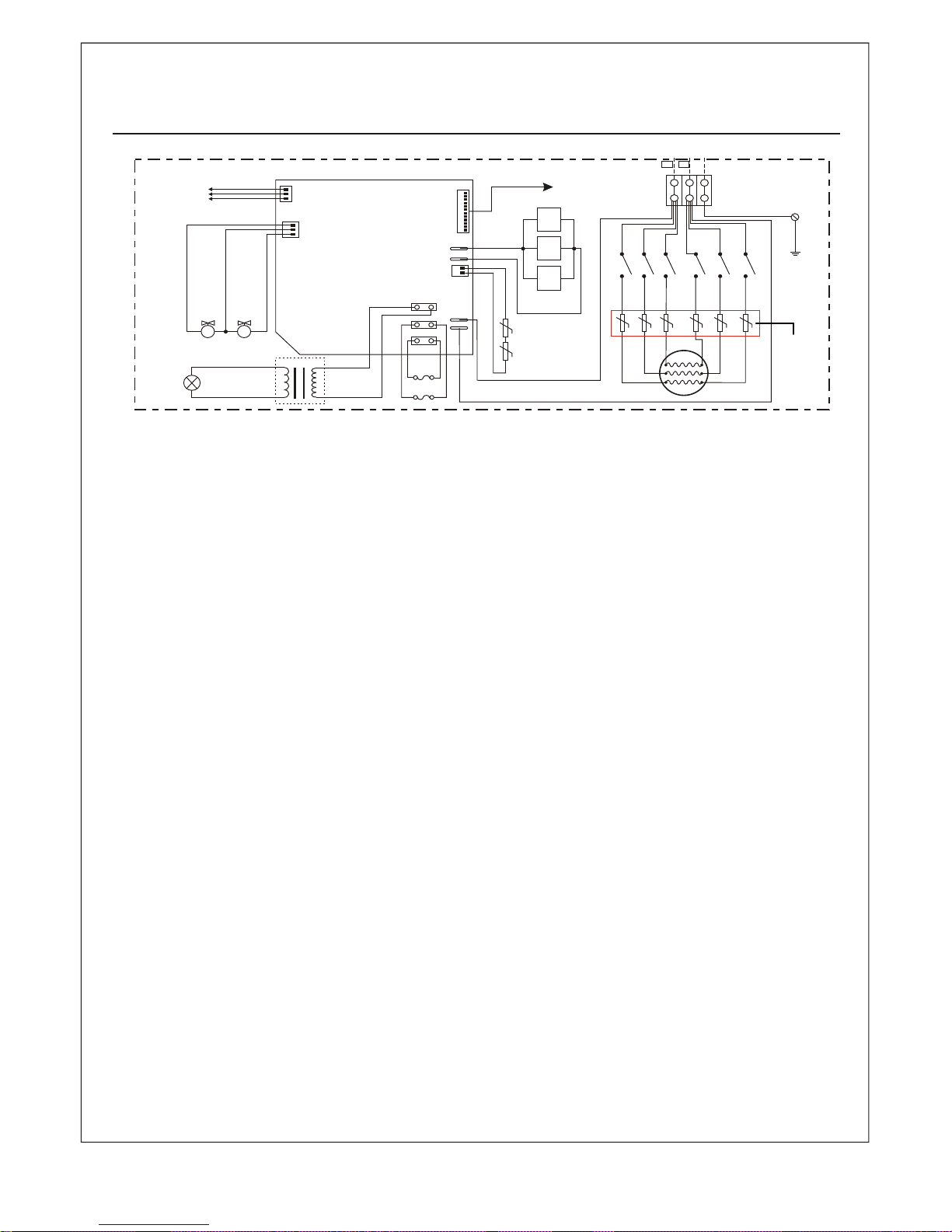
Steamcore Spa ** 10.5kW / 18kW (240V - 1PH)
auto reset
hi-limit
manual
reset
hi-limit
European Connection
( L2 = N "Neutral")
9
Page 12
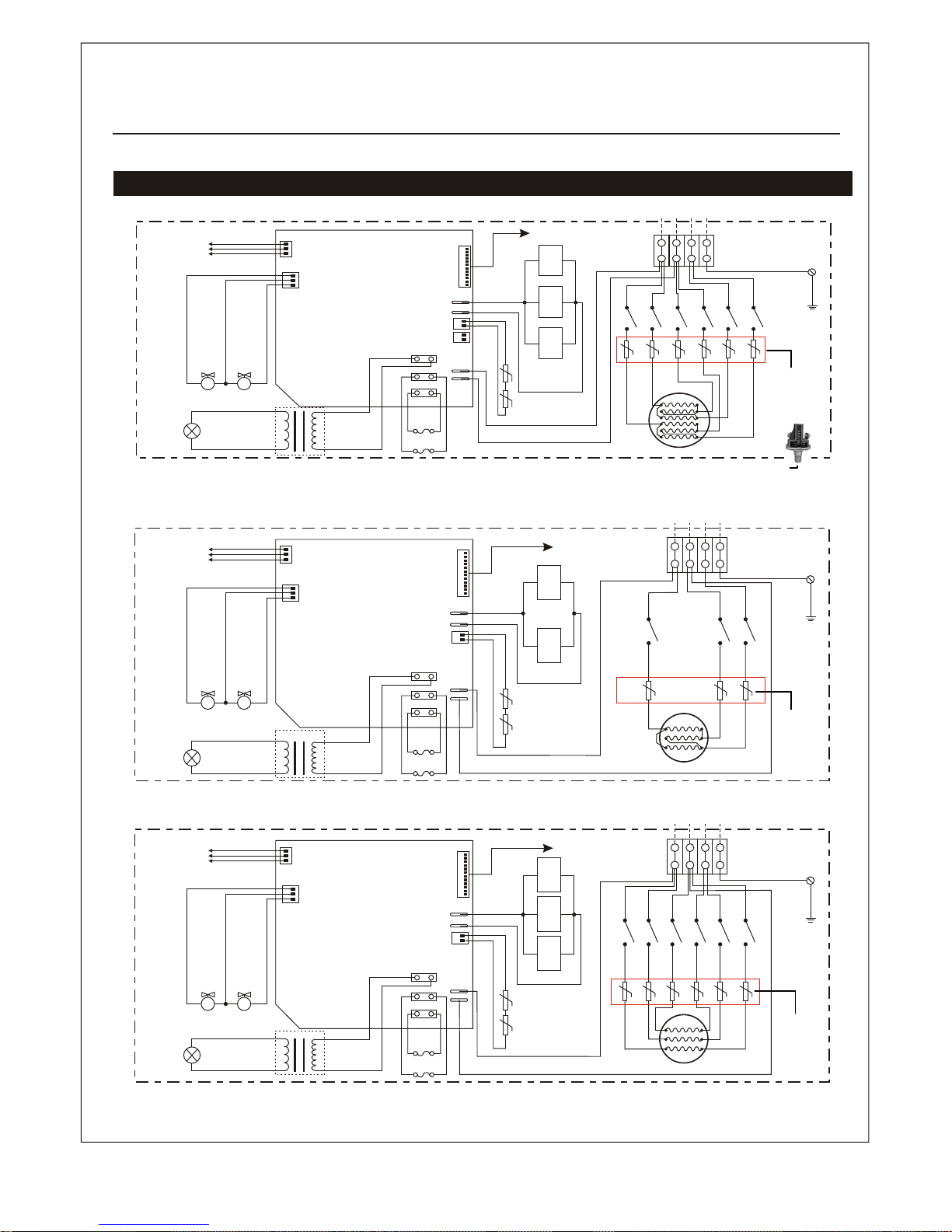
Wiring Diagram 208V (3PH)
J2-1
J1-2
J1-1
J1J2
S S
Supply
Red
Red
Black
Red
Red
To Control Panal
Fill water valve
Drain water valve
Terminal Block
Yellow/Green
Red
Black
Red
Black
Y ellow
Red
Black
Red
Red
Red
Red
Water Level Sensor
Red(Short Pin)
Black(Long Pin)
Yellow(Middle Pin)
Red
Red
Blue
Brown
Red
Light
G
L1L2L3
Red
Red
J2-2
J2-1
J3-1
J1J3
S S
Supply
Red
Red
Black
Red
Red
To Control Panal
Fill water valve
Drain water valve
Terminal Block
Yellow/Green
Red
Black
Red
Black
Y ellow
Red
Black
Red
Red
Red
Red
Water Level Sensor
Red(Short Pin)
Black(Long Pin)
Yellow(Middle Pin)
Red
Red
Blue
Brown
Red
Light
G
L1L2L3
Red
Red
J1-2
Red
Red
J1-1
Red
Red
J3-2
Red
Red
J2
To Control Panal
Terminal Block
J2-2
J1-1
J1-2
J3-1
J2-1
J3-2
J1J2J3
Yellow/Green
Red
Black
Black
Red
Black
G
Supply
L1L2L3
Red
S S
Fill water valve
Drain water valve
Yellow
Red
Black
Red
Red
Red
Red
Water Level Sensor
Red(Short Pin)
Black(Long Pin)
Yellow(Middle Pin)
Red
Blue
Brown
Red
Light
Optional
Optional
Optional
Steamcore Spa ** 15kW / 18kW (208V - 3PH)
Steamcore Spa ** 9kW (208V - 3PH)
Steamcore Spa ** 10.5kW / 12kW / 13.5kW (208V - 3PH)
Steamcore Spa **
manual reset
hi-limit
auto reset
hi-limit
auto reset
hi-limit
manual
reset
hi-limit
manual
reset
hi-limit
auto reset
hi-limit
12 psi pressure switch (UL - USA Application 18kw & Up)
European Connection
( L2 = N "Neutral")
10
Page 13
!
The calculation formula for selecting the size of steam generator is for
reference only. Due to the variability of the building, the specifications and size
illustration are used as guidelines only. If we have complete information, including
actual blueprint, project instruction and building details, we can select the type of
generator.
Important:
User Manual
Sizing steam generator
Measure the length, width and height (feet) of the current steam shower or bathtub area
Example;
L:7xW:5xH:8 = 280 Cubic Feet
You would need a 9000 watt (9KW) steam generator.
However, if your shower materials are;
x 25% for Ceramic Wall Finish = 61.25 (61.25+280) = 341 Total.
that has a ceramic wall finish.
(is multiplied by:)
Acrylic, cultured marble.
Ceramic Tile on Cement Board.
Ceramic Tile on Mortar Bed.
Glass or Glass Block
Porcelain tile on cement board
NATURAL STONE TILE (marble, granite, slate, travertine, etc)
On Cement Board.
On Mortar Bed.
Natural Stone Slabs over 1/2" thick
Each Exterior Wall(s) Insulated
0.08
1.30
1.30
1.35
1.60
1.90
2.00
2.25
1.10 for each outside wall
11
Page 14
!
Installation of the top light
CAUTION:
The rating
of the light should not surpass 3 Watts (rated power) to prevent damage to
the transformer.
!
CAUTION:
Take some moisture proof measures in the process of installation. Do
not let the electrical components be exposed to moisture or, it will cause damage or
short circuit.
The illustration is just for explaination,the practical installation must comply with
the nation's electric criteria, and performed by a professional licensed electrician.
!
CAUTION:
(Possible location)
The steam outlet
Under Sink
(possible location)
The steam generator
Light
The steam control panel
User Manual
The LED light should be installed on top of the steam room ceiling or in a place not accessible to children.
CAUTION: Installer must take some moisture proof
measures in the process of installation.
Electrophorus components cannot be
exposed to moisture, as it will cause damage
to the light components causing a possible
short circuit.
12
Page 15
1
2
3
5
4
6
12
14
11
8
10
7
15
17
16
1
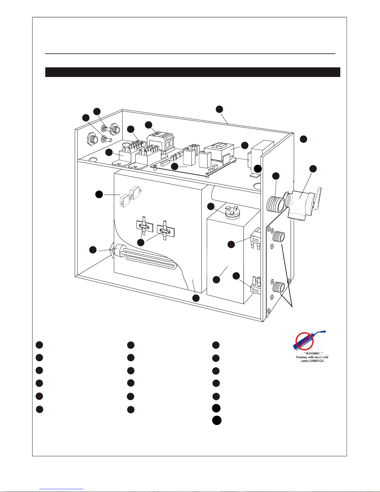
Enclosure
2
3
Circuit board
4
Steam Outlet
5
6
Water fill valve
7
Water drain valve
8
Subsidiary water tank
9
Main water tank
1
0
Heating Element
Heat Hi-limit
Transformer
11
12
Terminal block
Fuse
Ground wire connector
16
Relay
Water level sensor
17
15
14
13
Configuration of steam generator
Fuse
13
17
9
User Manual
Pressure Safety Valve
DO NOT HEAT
DURING INSTALLATION.
(heating with torch will cause
damage to plastic solenoid valve)
Mood light transformer
18
Manual Reset Hi-Limit
18
19
19
14
Page 16
!
!
!
Controller Maintenance
Safety and operation information of the controller
Warning:
If the installation and operation instruction is not read or understood, do
not install. In case there should be any dangerous installation and improper
operation.
Install the controller based on the installation instruction otherwise, the temperature in
the steam room will be too high or not heated enough.
If the controller is installed outside the steam room, the temperature sensor must be
installed in the steam room.
Caution:
Do not install the controller wire in the same conduit with high voltage electric
wire. Do not install close to hot water or steam pipe.
Important:
Before installing the controller, make sure the steam generator power is
off otherwise the controller may be damaged.
The instruction includes important safety, operation and maintenance information.
Keep the instruction in the user's hands.
If the steam generator is damaged or does not work normally, do not continue to install
or use the controller. Turn main power supply off.
User Manual
1. Use soft cloth with a mild soap/water to clean controller
2. Do NOT use harsh chemicals or cleaning products.
3. Do NOT mount controller directly over the steam nozzles.
4. If controller is readout is not stable or damaged, turn main power off and call a
service electrician to replace it.
15
Page 17
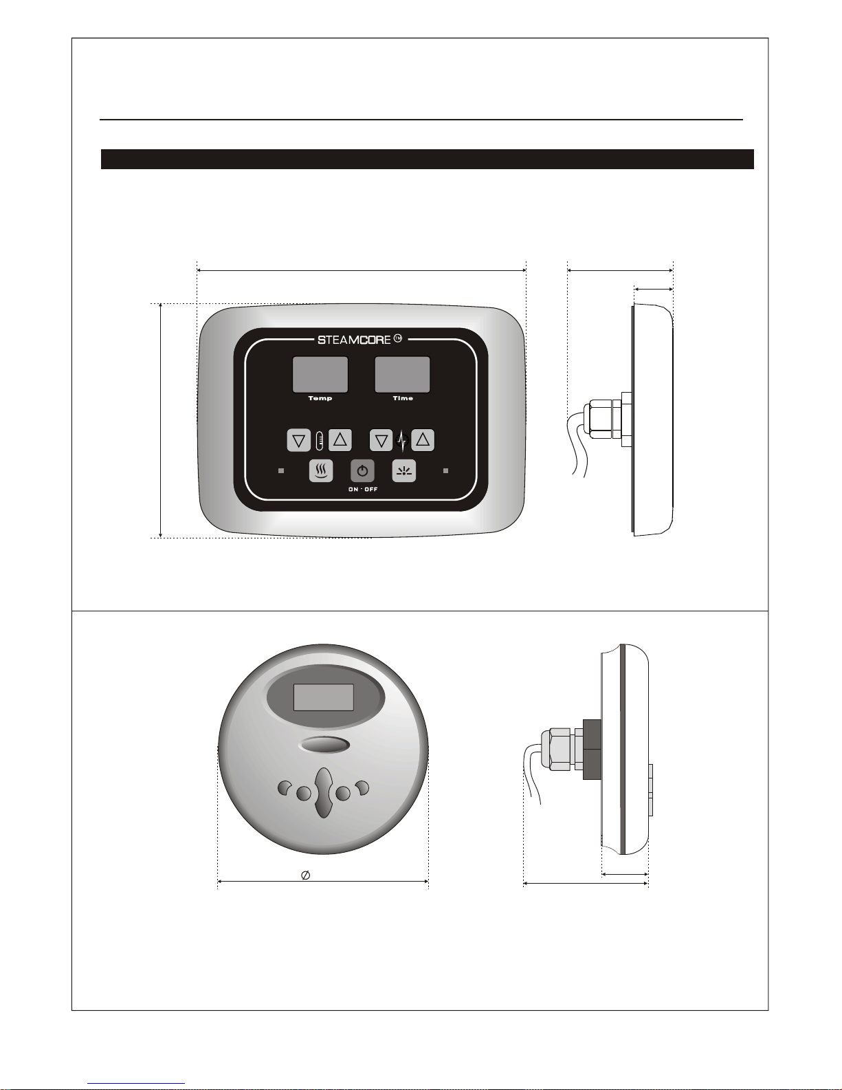
User Manual
Control panel (both SSI and SSII) dimension
113mm
25mm
75mm
SSI and SSII Control panel may be switched for Spa II
SS I
SS II
160mm
120mm
23mm
70mm
16
Page 18
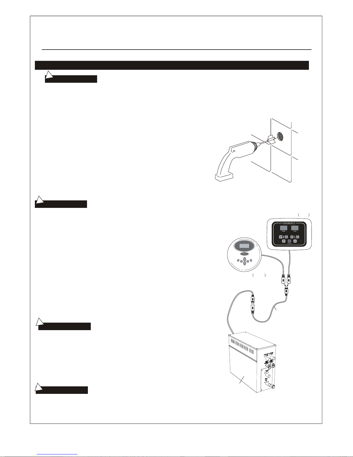
Installation instruction of controller
!
Important:
Before installing the controller, make sure the steam generator is shut off
otherwise the controller may be damaged.
!
Important:
User Manual
!
Important:
Do not install the controller under the
water pipe or in a position where water comes into contact.
!
Do not
pull tight, or clip tight
the
controller wire in case
of causing damage to it.
before
repairing
the
controller,
make
sure
the steam
generator
is shut off otherwise the
controller
may
be
damaged.
Important:
Aor
Control Panel
(1ft)
(1ft)
(20ft)
SS II
Extended wire
Steam Generator
Control Panel SS I
STEP 1
STEP 2
STEP 3
STEP 4
Determine the installation location of the controller. The controller is designed
to be installed in the steam room.
1. 4 - 5 ft from the finished steam room floor.
2. Away (not above) from the steam nozzle(s) and do not expose under
the direct path of steam.
3. Installation on vertical walls only.
4. The position of the installation should facilitate easy operation and
convenience of wiring. The controller wire is 1 ft long, with a supplied
20 ft extension control cable. The max length between the generator
and the controller should not exceed 20 ft at most. If longer lengths is
of control cable is needed, additional 20 ft cables can be purchased at
an extra cost. The max length of jointable cable run should not exceed
60 ft (3 cable sets of 20 ft).
Drill a hole of 1.5 inches (35mm) diameter. No larger or smaller.
Pull the controller cable through the round hole, connect it to the controller.
Make sure when installing the 20 ft cable that it is placed in the proper direction.
Make sure that the ends are corresponding with the controller and steam
generator plugs. When attaching the controller ends, do NOT twist, aim the
ends with the marked arrows and insert horizontally wit out twisting. Take
PRECAUTION to not damage the pins on each end of the controller cables.
Do the same if unplugging is needed.
Before activiating the main power supply, make sure there are no water
leaks and that all wiring connections are adequately tightened and secure.
Operate steam generator and make sure all items on the page function well.
17
Page 19
!
User Manual
Control Panel SS I
Control Panel SS I
Control Panel SS II
Temperature sensor
Locknut for temperature
sensor base
Drill
10
1cm
Ground
1.2~1.5m
(Fig.1) (Fig.2)
(Fig.3)
Temperature sensor
base (optional)
To
ensure horizontal
installation of the controller, use a
level if necessary.
Important:
Control Panel SS II
Temperature sensor installation(only for SS I )Control Panel
STEP FIVE
STEP SIX
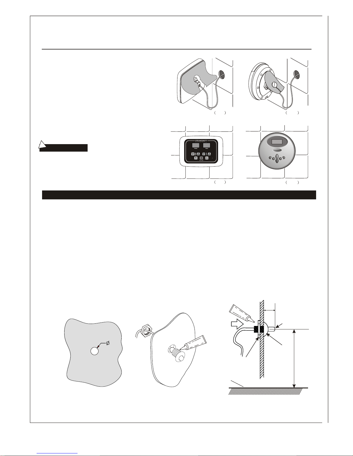
Remove the paper on the back side of the controller. To
expose the 3m adhesive tape. To achieve good adhesion
to the wall finish make sure it is clean and dry.
Locate the display screen in the direction of 12 o'clock,
and press the controller firmly to the wall finish.
1. The position of the temperature sensor for the SSI controller should be within a range of 4.5 - 5 ft (1.2M - 1.5M) from
from the steam room finish floor. Try to avoid installing in the vicinity of the steam nozzle(s) or the opening side of the
steam room door.
2. As shown Fig1, drill a small hole 3/8 inch (10mm) in the selected location.
3. Apply a bead of silicone along the edge of the back of the sensor base.
4. The sensor holder and nut is no longer supplied nor required.
5. Place sensor chrome tip within steam room and place small bead of silicone to create seal and hold sensor into place.
The temperature sensor should be installed by extending about 0.5 inch (1cm) from the front of the steam room
to make sure the speed and accuracy of temperature control.
18
Page 20
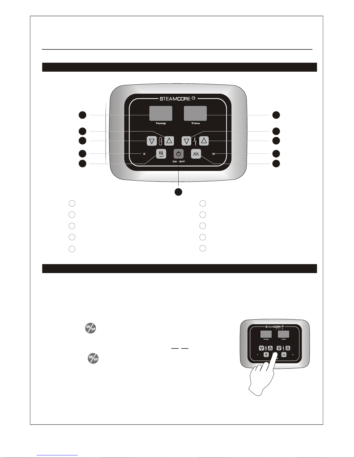
Illustration of the controller panel (SS I )Control Panel
User Manual
Operation instruction (SS I )Control Panel
1
5
2
10
2
1
2
Steam Temperature Adjust Key--HIGH
3
4
5
6
Steam ON/OFF
Power Indicator LED
LED SCREEN
Mood Light Indicator LED
Mood Light ON/OFF
Steam Time Adjust Key--LOW
7
8
9
10
Power ON/OFF
Steam Temperature Adjust Key--LOW
Steam Time Adjust Key--HIGH
2 9
3
2
8
2
4 7
6 6
Power ON/OFF
When unit is powered on, power indicator LED should be lit. Press
and release button to activate system and all function buttons.
Meanwhile, power indicator LED goes out. Water input steam boil
tank automatically, and LED screens display . Shut down the
system, press button again. System drains out water in generator
water tank automatically. (NOTE: If power indicator LED flashes
when system is activated, it reports that generator water tank is lack
of water. System shuts down power supply to heater elements, and
opens water inlet valve to refill water until reaching required volume.)
IN/OUT SHOWER USE
19
Page 21
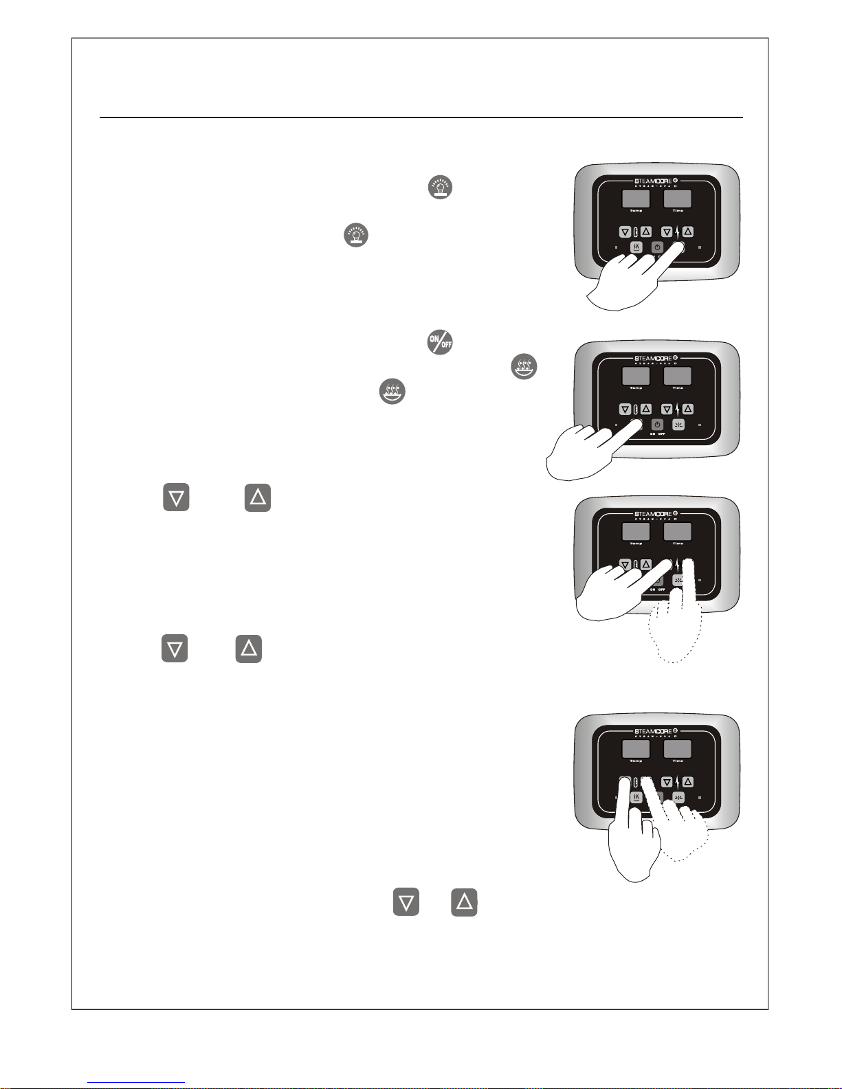
Steam Temperature Setting
Select Temperature Unit
Mood Light
Steam ON/OFF
Steam Time Setting
User Manual
When system is activated, press and release button to turn
on the mood light. Indicator LED on the right of the button
should be lit. Press and release button again to shut down
mood light.
When unit is powered on, press and release button, water
input steam boil tank automatically, press and release
button, steam starts emitting. Press button again to stop
steam.
Use and buttons to set desired steam time when
system is activated. Steam time LED screen shows set time
from 5 - 60 minutes. System shuts down power supply to heater
elements automatically when desired steam time is over.
Use and buttons to set desired steam temperature
when system is activated. Steam temperature LED screen
shows set steam temperature ranging from
. When ambient temperature is higher than desired
temperature, system shuts down powersupply to heater
elements automatically. Meanwhile, temperature readings on
LED screen flash until ambient temperature gets lower than set
temperature.
When system has been turned off, press and buttons at
the same time, LED screen shows current temperature unit.
TEMP
TIME
Do NOT set temperature setting more than 110F (45C).
5C - 45C or 50F - 110F.
20
Page 22
9
10
1
2
3
4
5
6
Fig.1
8
7
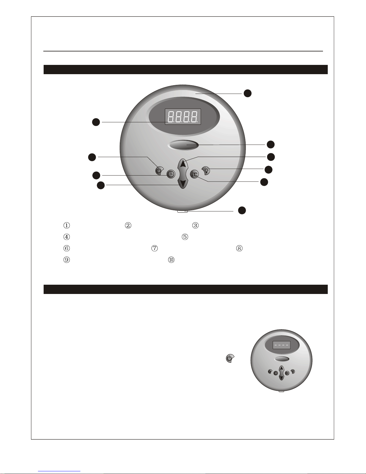
Illustration of the controller panel Control Panel
Power switch Time set button Time/temperature decrease button
Time/temperature increase button Light function button
Temperature set button Digital display screen Steamcore
The front decorative panel Temperature sensor
Operation instruction
The controller is digital temperature control system which can start, stop or pause in the
preset time to keep the temperature in the set number.
ON/OFF
When it is electrified, the system shuts off all the loads to
remain in a waiting state, and the digital tube will display ---(as is shown in Fig.1). In the waiting state,press button to
turn on the system and the steam function. The default time of
starting the steam is 30 minutes and it begins to count down
and the default temperature of the steam is 110F. After the
system is started, the digital tube will display the current
temperature of the environment and the temperature check
range is
User Manual
IN SHOWER USE ONLY
50F - 110F.
(SSII & SQII)
(SSII & SQII Control Panel)
21
Page 23
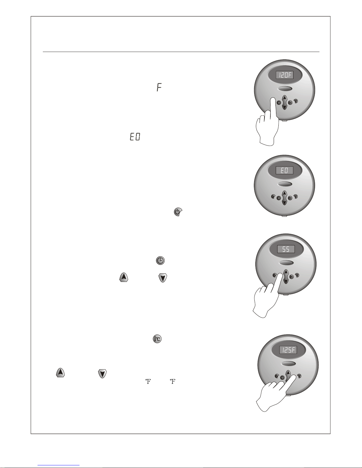
Fig 2
Fig.3
Fig.4
Fig.5
When the actual temperature is smaller than or equal to 32 , the
digital tube will display 32 . When the actual temperature is
smaller than or equal , the digital tube will display
. The last digit displays as the unit of Fahrenheit
temperature. The default start time of steam function is 30
minutes. When the steam is starting, there is a shortage of water,
the heating wire will stop heating and the water input valve will
start automatically. If there is no water tested in 5 seconds or no
water coming to reach the full volume in 15 seconds, the digital
tube will flash to display (as shown in Fig.3) to hint mistake.
If the water is full, the steam function will return to normal.
When the steam function is started, if the temperature of the
environment is higher than the set steam temperature, the
heating wire will stop heating, the digital tube will flash to
display the current environment temperature; when the
environment temperature is lower than the set steam
temperature, the heating wire will restore heating, the digital
tube will display normally current environment temperature.
When the system is started, press button or when the
steam function time is due, the system will be shut. 10 minutes
after the system is shut off, the drainage function will be started
automatically for 5 minutes.
Time setting
When the machine is started, press button and the digital tube
will display the remaining time of current steam function (as
shown in Fig.4), press button or button to adjust the
remaining time. The adjustment range is 5-60 minutes with
minute as one level. If there is no adjustment in 5 seconds, the
system will quit the time setting function. The digital tube will
restore to display current environment temperature.
Temperature setting
Whenthemachine is started,press button and the digital tube
will display the set steam time (as shown in Fig.5), at the same
time the temperature unit will flash to hint that the machine has
entered the steam temperature setting function. At this time, press
button or button to adjust the temperature parameter.
The adjustment range is 50-10 with 1 as one level. If there is
no adjustment in 5 seconds, the system will quit the temperature
setting function. The digital tube will restore to display current
environment temperature.
User Manual
Do NOT set temperature setting more than 110F (45C)
to 110 F
110 F
F
F
22
Page 24
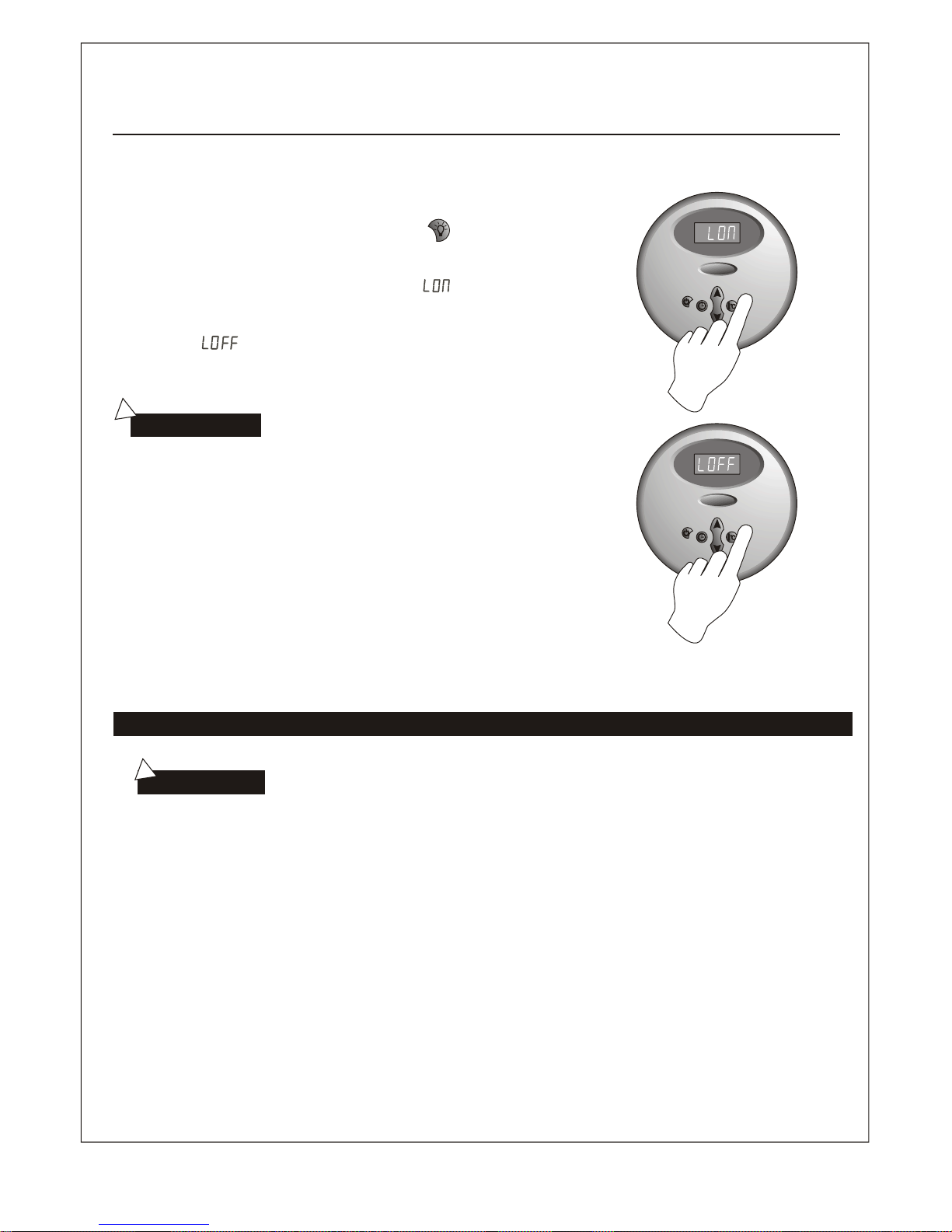
Light function
Fig.7
!
User Manual
1.Please consult your physician before using.If you are
pregnant,elderly,have high blood pressure,diabetes,
suffering from heart disease, intoxicated,or not in good
health, do not use this steam bath.
2.Children must be accompanied with adults when using
this steam bath.
3.Steam is hot! Severe burn will occur if you come in contact
with the steam head or steam emitting from the steam head.
CAUTION:
!
Fig.6
When the machine is started, press button repeatedly to
turn on/off light function. When the light is turned on, the
digital tube will temporarily display (as is shown in Fig.6).
When the light is turned off, the digital tube will temporarily
display (as is shown in Fig.7).
Maintenance of the steam generator
Important: Automatic water discharge operation
after each
use.
1. The steam generator automatically performs a water discharge operation after every use.
2. Wait for the completion of the automatic water discharge after each time using the steam generator to make
sure the water in the tank is discharged completely before cutting off the power supply.
3. There should not be any leakage or damage among the steam generator, steam nozzle(s), components and pipes.
They should be checked periodically and repaired.
4. Clean the water supply lines once a year.
5. Check water connection to ensure they are tight, and not damaged to over heating.
6. Check the sediments accumlated in the water boiler tank, and heating elements within boiler tank. If the sediments
are thick, dispose of it in time. (using diluted lemon acid to soak for 15-30 minutes).
7. Remove water level sensors from boiler tank once a quarter year (3 months) to clean the sediments on the
water level sensing rods/probes.
8. According to the National and Local Plumbing Codes, the steam generator drain valve should be equipped with
a drain pipe. The steam generator drains by way of gravity, and pitch is required. Check local code requirements
for drain valves. Do NOT connect the safety valve or steam line(s) to the drain line.
23
Page 25
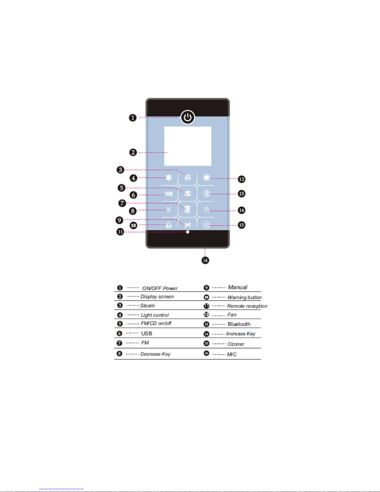
Congratulations on your new Saunacore steam unit with the advanced IntelliSteam
controller!
This booklet will help you get the most enjoyment out of your device’s many capabilities and features.
Steamcore IntelliSteam Operating Instructions
24
Page 26

NOTE 1: All controller keys are touch-sensitive, and do not require physical pressure.
NOTE 2: The power button, located on the upper front of the unit, performs several different functions, depending
if it’s touched momentarily, or “held” for several seconds. It also is an LED indicator which glows:
RED- System in standby mode
GREEN- (Display indicator flashing) Keypad is locked, keys are disabled.
GREEN- (Display indicator is steady) Keypad is unlocked, commands can be entered.
WHITE- System on, radio/CD function in use.
1.Power On/Off
When the system is in standby mode (Indicator is Red), touch the Power Key for 3 seconds or more. The display
will light up, and glow green. Momentarily touching the Power Key returns the unit to standby. The unit will enter
auto-shutdown in 1 hour if no buttons are touched during that time.
2.Unlocking the controller
If no function keys are touched for 20 seconds, the system will auto-lock the keypad, and the Dotted line/ Solid
line indicator on the display screen will flash. Touching the Power Key for 3 seconds will unlock the system, making
all keys active.
3. Using the Steam Function
With the system on, touch the Steam key to initiate steam generation. (The radio must be off to initiate the steam
function). An indicator will show this operation on the display. Default temperature is set at 45deg. C. The timer
default is set at 60 minutes. An indicator will flash several times while the water is being filled. (In the event the
water supply to the unit is interrupted, the indicator will flash continuously, and the steam function will shut off).
4. Steam Adjustments
(Power on, steam function selected)
1. Steam Time adjustment: Touch the M key to select “time”, and use the Up or Down keys to choose your
preferred time, from 1-60 minutes.
2. Steam temperature adjustment: Touch the M key a second time to select temperature, and use the Up or Down
keys to choose your preferred temperature, from 25deg C to 45deg. C.
25
Page 27

5.Ozoner (opt)
With the system on, touch the O3 key to initialize the ozone function (if unit so equipped). To turn off, touch the
O3 key again.
6.Fan (opt)
With the system on, touch the Fan key to turn it on. The display will indicate fan operation.
7.Light (opt)
The Light key will operate the lights in several ways, as follows:
With the system on, touching the Light key once turns on the background light (display shows L1). Touch it again,
and the top light also comes on (display shows L2). A third touch turns them both off.
8.FM/CD
Your IntelliSteam controller comes with a built-in FM tuner. Touching the Radio key once will turn on the tuner.
This is indicated on the main screen as a standard radio tuner. Touching the key a second time switches the
function to CD (if unit so equipped). This will be indicated on the screen instead of the tuner. A third touch shuts
the CD function off completely. If no CD is installed, touching the Radio key a second time will simply turn off the
radio function.
9.Radio Tuning/Search
(Power on, radio function selected)
1. Auto-search/ store: Touch the TUN key for 2 seconds or more to turn on auto-search/store. The tuner range is
from 97.5-108.0MHZ, reception location-dependant. This will store the strongest available signals in memory.
2. Manual-search/ store: Touch the TUN key momentarily , and the tuner indicator will flash. Touch the Up or
Down keys to tune in your desired station, then touch the TUN key to store it in memory.
3.To add a favourite station, again use the Up or Down keys to find a favoured station. Once you have, touch the
TUN key to store it. Up to 32 stations can be stored. (Storage locations are named c1, c2, c3, etc. on the display).
4. Volume adjustment: Touch the TUN key and use the Up or Down keys to adjust the volume to your preference.
Volume is shown on the display as a number, then a “d”. (for example, 25d, 30d, 35d, etc.).
26
Page 28

10. MP3 Feature
Turn on the system, and plug your flash drive into the provided USB slot. Touch the USB key, and your music will
play automatically. The screen will display the current music title, remaining time, etc. Press the Up key to jump to
the next track (s), or the Down key for the previous track(s). Touch the TUN/TEL key to pause playing, and touch it
again to resume. Touch the USB key again to turn it off.
11. Bluetooth
1. First, turn on your smart phone’s Bluetooth function, and search for new devices. (normally, there is one
Bluetooth device to be found). This should be done in close proximity to your IntelliSteam controller.
2. With the system on, touch the Bluetooth key. The indicator will flash, and a “bt” will be indicated on the display.
3. Select the device Bluetooth on your phone, and the pair should connect automatically. Once this occurs, the
indicator will remain lit, confirming a successful connection. Some smartphones may require entering a password
during the pairing connection process. Use the default “0000” password for this. After connecting, touch the
Bluetooth. Now you can use Bluetooth to play music or answer a call. Touching the Up key skips to the next song,
and touching the Down key skips back to the previous one. Touch TUN/TEL to pause playing, and again to resume
play. When you receive an incoming phone call, touch TUN/TEL to answer, and again to hang up. Touching the
Bluetooth key again will turn off the Bluetooth function.
4. Each time the control panel is turned on, it will search for the last connected Bluetooth device, and attempt to
reconnect to it automatically.
12.Telephone
(Incoming calls only)
This function (if line is installed) utilizes the unit’s built-in microphone, on the bottom right of the controller. When
a call comes in, the speakers are muted, and the TUN/TEL indicator will flash. To answer, touch the TUN/TEL key.
Touching the Up or Down keys will adjust the volume to your preference. To hang up, simply touch the TUN/TEL
key again.
13.Warning System
In the event of an emergency, a warning key is built-in to each IntelliSteam controller, giving you an added
measure of assurance. With the system on, a touch of the Warning key will cause a loud alarm to sound, and turn
on the lights and fan. This can easily be turned off by touching the Warning key again.
27
Page 29
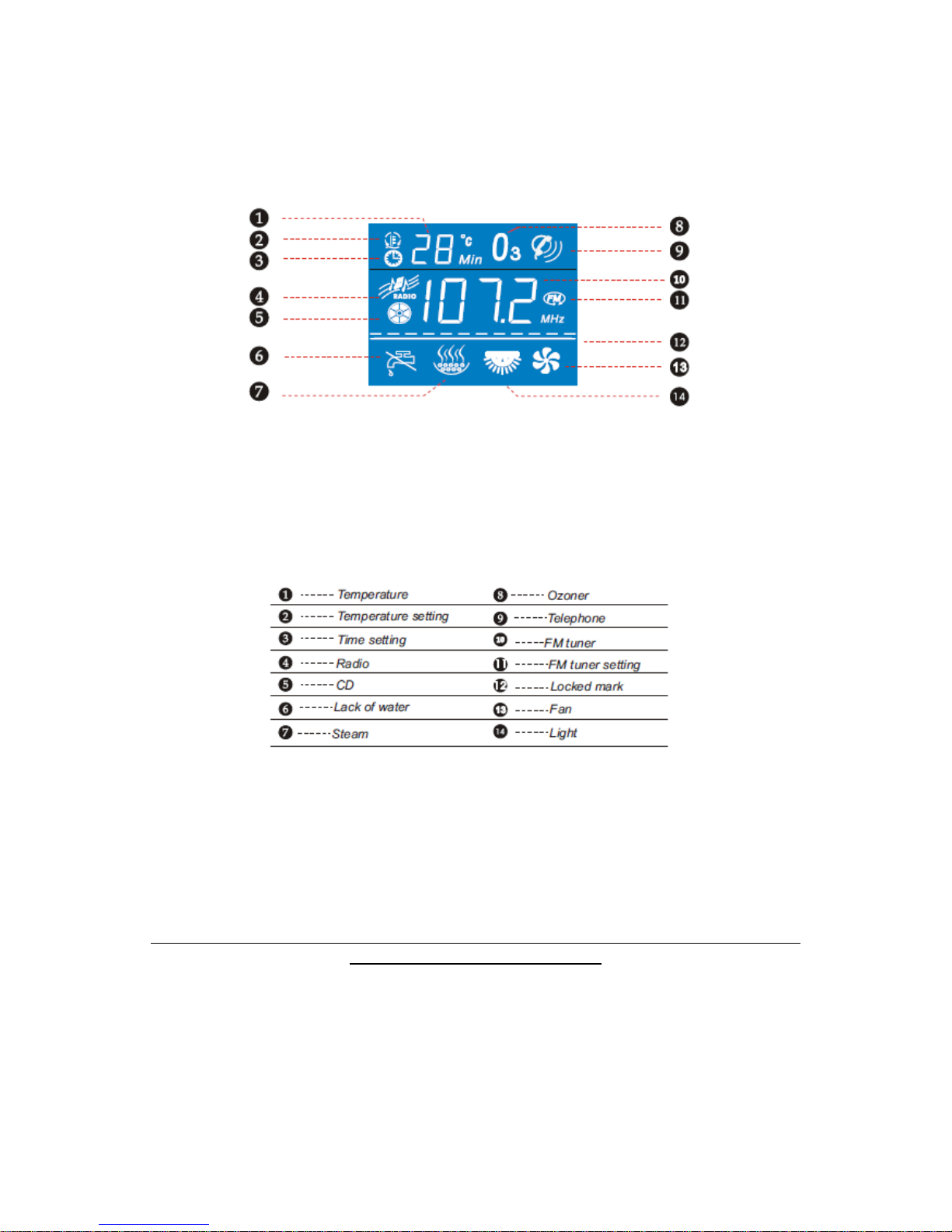
This set of instruction pages is to be used in combination with the Steamcore Steam Bath installation manual
provided with each steam bath generator.
28
Page 30
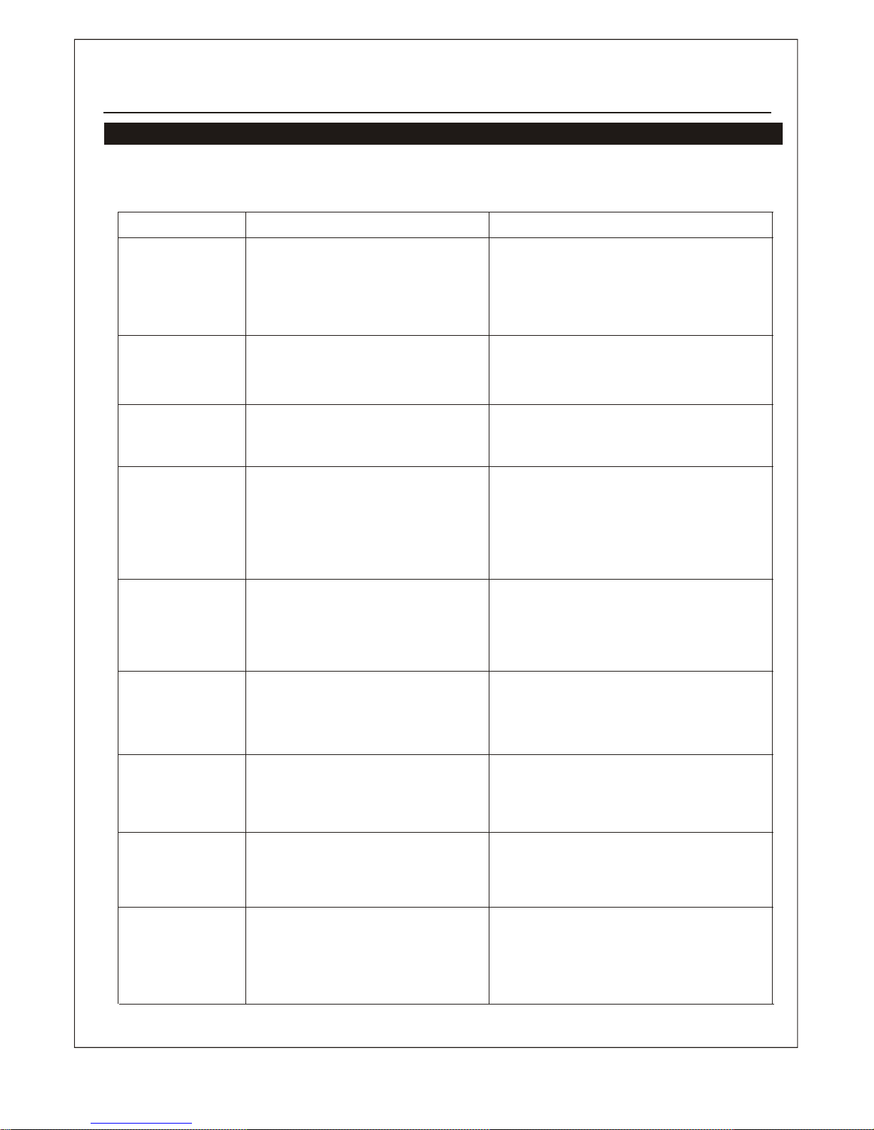
Common trouble shooting methods
To facilitate your use and maintenance of sauna room, the following common
trouble shooting methods are listed for reference.
Troubles
Causes of troubles
Trouble-shooting methods
The machine
does not start
when
electrified
1.The fuse is burned.
2.The wire connection terminal
becomes loose.
3.Not good contact in the
connection wire between the
controller and the steam engine.
1.Change the fuse (on the shell 0.8A/
250V)
2.Plug tight the wire connection terminal
3.Make sure the steam engine and the
controller come into good contact
Electricity
leakage switch
breaks
automatically
1.The wire connector is dampened
or damaged.
2.The heating tube breaks
1.Check whether the wire connector is
dampened or damaged, and dry with
dryer if dampened.
2.Change a heating tube.
When the machine is
started, hot water
comes out with little
or no steam
1. The water drainage valve is broken.
1. Change a water drainage valve.
The display screen
on the control panel
does not display
1.The power wire is not connected well
or not in good contact. The connection
plug between the control panel and the
electrically-controlled box becomes
loose.
2.Trouble with plugboard.
1.Check whether the connection plug between
the control panel and the electricallycontrolled box has become loose, and
whether the power circuitry has good contact.
2.Change a plugboard.
Water leakage
1.The water pipe connector becomes
loose or the pipe breaks
2.Water leakage in the water input
valve or the waterdrainage valve
1.Tighten the loose connector, and change the
broken pipe.
2.Change the water input valve or the water
drainage valve.
No steam when
starting the
machine
1.No electricity.
2.No water.
3.The set temperature is too low
4.Troublewithwire.
1.Check the power supply
2.Check the water input pipe and water input
valve
3.Reset the temperature
4.Contact the distributor
The steam does not
come out, the water
sounds in the
machine
1. The steam pipe is jammed.
1. Cut power supply to check whether the
steam pipe is smooth.
The light can not
be turned on
1. The fuse is burned.
2. The light is broken
3. The wire is broken
4. The plug does not have good contact
1.Change the fuse (on the shell 1A/250V)
2. Change a light bulb.
3. Change wire.
4. Make the contact good.
The display box
displays normally
with no steam
input
1.Too much pressure inside the steam
engine, so the system breaks for heat
protection.
2.Wire is broken for heat protection.
1.Check the steam transport pipe and restore
automatically after heat protection
becomes cool.
2.Check the heat protection wire to make sure
the connection is good.
User Manual
Technical Hotline 905-951-6662
29
Page 31
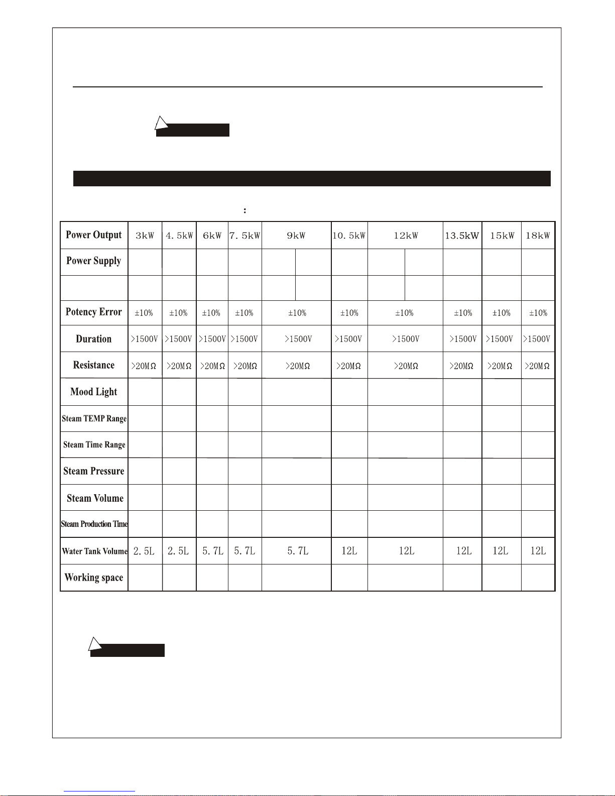
TYPE Steamcore Spa II
!
!
Important: Consult a licensed electrician for service.
Technical parameter
The parameter listed in the table will vary from different place and
temperature,please consult with qualified designer and architect for more
detailed use.
Important:
208V
(3PH)
50-10F
~
Min
~
Min
~
Min
~
Min
~
Min
~
Min
~
Min
~
Min
~
Min
240V
(1PH)
240V
(1PH)
240V
(1PH)
240V
(1PH)
240V
(1PH)
208V
(3PH)
208V
(3PH)
Current(A)
User Manual
~
Min
208V
(3PH)
240V
(1PH)
208V
(3PH)
240V
(1PH)
12.5A
18.75A
25A x 3
31.25A
37.5A
43.75A
33.3A x 3
37.5A x 3
41.7A x 3
50A x 3
25A
50A
12V/40W 12V/40W12V/40W12V/40W 12V/40W 12V/40W 12V/40W 12V/40W 12V/40W 12V/40W
0.12MPa 0.12MPa
0.13MPa 0.14MPa 0.14MPa 0.15MPa 0.16MPa 0.17MPa 0.18MPa 0.19MPa
500ml/Min450ml/Min400ml/Min360ml/Min300ml/Min260ml/Min220ml/Min
180ml/Min160ml/Min140ml/Min
100-150S 90-120S
100-160S
90-140S 80-130S 180-240S 150-160S 130-150S 120-150S 90-140S
18~22
15~20
14~18
12~15
10~13
8~12
6~10
5~8
4~7
3~6
50-10F 50-10F 50-10F 50-10F 50-10F 50-10F 50-10F 50-10F 50-10F
30
Page 32

STEAMCORE
Saunacore warrants these products to be free from defects in material and workmanship and
agrees to remedy any such defect. This warranty does not apply outside the boundaries of the
United States, Canada or any product which in our sole opinion has been im properly installed,
or subject to willful abuse, misuse, alteration, and shipping damages during the period of coverage.
Postage and handling charges of the product to and from Saunacore for warranty repairs and
for any related charges for the installation / removal of these products are NOT included in your
warranty. Warranty service can be obtained by sending your product to Saunacore
(Call 905-951-6662). Warranty repairs must be done only by Saunacore. Proof of purchase
and a serial number of the product will be required before any services are performed.
Warranty applies only to the original consumer purchaser, warranty is non-transferable.
For warranty repair, the steam generator must be returned to Saunacore with an Return materials Authorization #
and is to be obtained by the original consumer purchaser and must be shown on all correspondence
and packing, without this RMA # returns for repairs will NOT be accepted.
Controls & Cables: One Year Parts and Labor
Steam Generator Only: One Year Parts and Labor
Second Year to Fifth Year Warranty Claim Fee (Admin/Deductible Fee) Applies $150.00
Steambath Generator Limited Warranty
Spa II Series Steambath Generator Limited Warranty
Steam Generator Components: Continuing after First Five Years of original consumer purchase date.
Components Only Coverage
Components Warranty (excluding auto drain, control, and cables) provided
the original consumer purchaser agrees to pay all labor costs/fees incurred
in connection with such repair.
Warranty work will be performed when the steam generator is returned to a
designated Saunacore location with a RMS number.
WARRANTY does not cover damages caused by Calcium, Lime Stone build up or corrosion to the components
to the steam generator.
_ _ _ _ _ _ _ _ _ _ _ _ _ _ _ _ _ _ _ _ _ _ _ _ _ _ _ _ _ _ _ _ _ _ _ _ _ _ _ _ _ _ _ _ _ _ _ _ _ _ _ _ _ _ _ _ _ _ _ _ _ _
Warranty RRegistration CCard
Model # ____________________________________ Serial # __________________________________
Purchase Date ________________________________________________________________________________
Dealer Name and Adress
____________________________________________________________________________________________
Owner Name and Address
____________________________________________________________________________________________
NOTE: A COPY OF THE RECEIPT MUST ACCOMPANY THIS WARRANTY CARD.
 Loading...